Sign In
Upload
Manuals
Brands
Aspen Avionics Manuals
Monitor
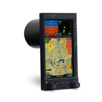
Evolution EFD 500 MFD
Aspen Avionics Evolution EFD 500 MFD Manuals
Manuals and User Guides for Aspen Avionics Evolution EFD 500 MFD. We have
2
Aspen Avionics Evolution EFD 500 MFD manuals available for free PDF download: Pilot's Manual, Pilot's Manual Addendum
Aspen Avionics Evolution EFD 500 MFD Pilot's Manual (214 pages)
FLIGHT DISPLAY
Brand:
Aspen Avionics
| Category:
Monitor
| Size: 8 MB
Table of Contents
Table of Contents
5
Copyrights and Trademarks
19
Approvals
20
LIMITED WARRANTY Aspen Avionics, Inc
21
Weather Data Warranty
24
XM WX Satellite Radio Service Agreement
25
Conventions
27
Covered Functionality
27
Terminology
27
Table 1 EFD1000/500 MFD Terminology
28
Pilot Interface Modes
29
Table 2 Pilot Interface Modes
29
Color Philosophy
30
Table 3 Color Convention
30
Warnings, Cautions, and Notes
31
Table 4 Warnings, Cautions, and Notes
31
Example Graphics
32
Pilot Familiarity
32
Map Orientation
32
Chapter 1 Welcome & Introduction
33
Figure 1-4 Trio Display System: PFD & Dual Mfds
35
System Hardware
36
EFD1000 Display
37
EFD500 Display
38
Remote Sensor Module (RSM) (EFD1000 MFD Only)
38
Configuration Module (CM)
39
Analog Converter Unit (ACU) - Optional
39
Evolution Weather Receiver (EWR50) and Antenna - Optional
40
Microsdhc Card
40
Chapter 2 MFD Overview
41
Navigation Map
41
XM WX Satellite Weather
42
Terrain and Obstructions
42
Traffic
43
Manual Reversionary Mode (EFD1000 MFD Only)
44
Switch to the PFD Operating Mode
44
Switch Back to MFD Operating Mode
44
Secondary PFD Display
45
Secondary Attitude Indicator
45
Secondary Horizontal Situation Indicator
45
Chapter 3 Display & Controls
47
Figure 3-2 Full Screen LAYOUT
48
Figure 3-4 Thumbnail Screen LAYOUT
49
Table 3-1 EFD1000/500 MFD Display Components
49
Default Display
50
Figure 3-6 EFD1000/500 MFD Page 2/3
51
Table 3-2 Split Screen LAYOUT WINDOW Supported Views
51
Figure 3-7 EFD1000/500 MFD PAGE 3/3
52
Table 3-3 Thumbnail LAYOUT WINDOW Supported Views
52
Data Bar
53
Controls
54
Left Knob
54
Lower Controls
54
Left Button
55
Middle Button
55
Right Button
55
Right Knob
56
Side Buttons
56
Range +/- Button
56
Reversion (REV) Button
56
Hot Keys/Menu Keys
57
Menu Button
57
Chapter 4 Getting Started
59
Startup
60
Figure 4-2 EFD1000/500 MFD Database Confirmation Screen
61
Select Different PAGE or WINDOW
62
Selected
63
Change VIEW
64
Table 4-1 EFD1000/500 MFD VIEW Names
64
Panning
65
Editing Airport Identifier Fields
66
Scroll Bar
67
Main Menu
68
Using the Menus
68
Figure 4-17 Main Menu Navigation Mode
69
Table 4-2 Menu Text
70
Figure 4-20 Main Menu Text - Editable
70
Figure 4-25 EDIT VALUE Displays above Right Knob
71
Display Lighting
72
Table 4-3 Lighting Mode Descriptions
73
Figure 4-27 Display Brightness in AUTO Mode
73
Backup Battery
74
Power Override
76
Power Off/Rev Button
77
Range Button
78
Cleaning the Display Screen
78
Chapter 5 Reference Guide
79
Navigation Map
80
Table 5-1 Navigation Map Hot Keys
80
Table 5-2 Navigation Map Feature Groups
82
General Map Settings
83
Table 5-3 Main Menu Navigation Map Settings
83
Map Symbols
84
Table 5-4 Navigation Map Heading Settings
85
Table 5-5 Feature Group Layering, Range, and Declutter Behavior
87
Figure 5-4 Editing OTHER APTS Feature Group
88
Map Range
89
Deactivate Auto-Range
90
Turn Auto Range off or on
90
Change the GPS Navigation Source
91
Change the Map Feature Declutter Level
91
Invalid GPS
92
GPS Information
91
Map Declutter
91
Airport/Vor Information
93
Table 5-6 Airport/Vor Information
95
Flight Plan
96
View Airport/Vor Information
96
Change the Map Style
97
Map Styles
97
Overlays
98
Airways Overlay
98
Show the Airways Overlay
98
Show the Terrain Overlay
99
Table 5-7 Navigation Map Terrain Overlay Color Coding
99
Terrain Overlay
99
Lightning Overlay
100
Show the Lightning Overlay
100
Data Link Weather Overlay
101
Show the Data Link Weather Overlay
101
Show the Traffic Overlay
102
Traffic Overlay
102
Data Link Weather (Optional)
104
Selecting Data Link Weather Products
106
View Different Data Link Weather Products
106
Convective
107
Table 5-8 Convective Overlay Hot Keys
107
Display the Convective Legend
110
Hide the Convective Legend
110
Hide or Display Convective Overlays
110
Metar
111
Table 5-9 METAR Declutter Settings
111
Display the METAR Legend
112
Hide the METAR Legend
112
Display Multiple Airports' METAR Information
113
Display an Individual Airport's METAR Information
114
Echo Tops
115
Display the Echo Tops Legend
115
Hide the Echo Tops Legend
115
Increase or Decrease Echo Top Altitude Filter
116
Cloud Tops
117
Display the Cloud Tops Legend
117
Hide the Cloud Tops Legend
117
Increase or Decrease Cloud Top Altitude Filter
117
Airmet/Sigmet
118
Table 5-10 AIRMET/SIGMET Symbology and Associated
119
Display/Hide the AIRMET/SIGMET Legend
120
Display AIRMET/SIGMET
120
Display AIRMET/SIGMET Information
121
Figure 5-56 METAR Product VIEW with MTOS Selected
121
Tfr
122
Figure 5-59 TFR
122
Display TFR Information
123
Figure 5-60 TFR Selected
123
Winds Aloft
124
Figure 5-63 Winds Aloft Screen at 500 Nm
124
Display the Winds Aloft Legend
125
Hide the Winds Aloft Legend
125
Increase or Decrease Winds Aloft Altitude Filter
125
XM Status
126
Figure 5-66 XM Status
126
Signal Quality
126
Table 5-11 XM Signal Quality Levels
126
Status Message
127
Table 5-12 XM Status Messages
127
Control States
128
Table 5-13 XM Control States
128
Descriptive Messages
129
Table 5-14 XM Status Operational Messages
129
Display XM Products' Age
130
Table 5-15 XM Status Error Messages
130
XM Product Page
130
Table 5-16 Weather Product Age Limits and Update Frequency
131
Table 5-17 Weather Age Annunciations
132
Dedicated Hazard Awareness Views
133
Figure 5-68 Dedicated Hazard Awareness – Terrain
133
Change Terrain Range Ring
134
Figure 5-69 Terrain VIEW Showing an ARC Range Ring
134
Terrain and Obstructions
134
Table 5-18 Terrain Color Coding
135
Figure 5-70 Invalid or Failed GPS Annunciations
136
Table 5-19 Obstruction Symbology
136
Traffic (Optional)
137
Figure 5-71 Dedicated Hazard Awareness – Traffic
137
Change Traffic Range Ring
138
Traffic Display
138
Display of Traffic Symbols
139
No Bearing Advisories
140
Off Scale and Symbol Overlap
140
Table 5-20 Traffic Sensor Status Display Annunciations
141
Traffic Operational Modes
141
Altitude Filter
142
Table 5-21 TIS Traffic Annunciations
142
Table 5-22 Traffic Filter Parameters
142
Change the Traffic Altitude Filter
143
Display a Traffic Advisory
143
Figure 5-76 Traffic Advisory
143
Traffic Advisories
143
Change WX-500 Range Ring
144
Optional)
144
Activate WX-500 Self-Test
145
Figure 5-84 WX-500 VIEW in Self-Test Mode
145
Annunciations
146
Table 5-23 WX-500 Annunciations
146
Clear WX-500 Rate
145
Display WX-500 Cells
145
Display WX-500 Strikes
145
Secondary Views (EFD1000 MFD Only)
147
Secondary Attitude Instrument (AI)
147
Airspeed and Altitude
147
Figure 5-86 ADAHRS FAIL
148
Secondary Horizontal Situation Indicator (HSI)
149
Figure 5-88 Secondary HSI
149
Modify the Course Setting
149
Vertical Deviation Indicator (VDI)
150
Chapter 6 Expanded Emergency & Abnormal Procedures
151
Pitot/Static System Blockage
151
CROSS CHECK ATTITUDE Message
152
Blocked Pitot or Static Line Suspected
152
Cross Check Attitude
152
Abnormal Shutdown Procedure
153
MFD Reversionary Mode Operation (EFD1000 MFD Only)
154
Select REV Mode
154
Loss of or Degraded Aircraft Power or on BAT Annunciation
155
GPSS Operation, Annunciations, and Autopilot Modes
156
When GPSS Automatically Changes to Wings Level Mode
157
Disable GPSS
157
EBB Disconnect (EFD1000 MFD Only)
158
Isolate the Emergency Backup Battery
158
Power Override
159
View External Voltage Status
159
View Internal Battery Status
159
ADAHRS Attitude Disagreement
160
In-Flight ADAHRS Reset
160
Reset EFD1000 ADAHRS
161
EFD1000/500 Intercommunications Failure
162
Intercommunications Failure
162
Loss of GPS Information
163
MFD Database Card
164
Warning, Caution, and Advisory Summary
165
Figure 6-13 Battery Countdown
165
Figure 6-14 Battery Operational
165
Figure 6-15 Attitude Fail
165
Figure 6-16 Direction Indicator Fail
165
Table 6-1 Warning Annunciations
166
Figure 6-19 Cross Check Attitude
167
Figure 6-20 ADAHRS FAIL
167
Figure 6-21 CROSS LINK FAILURE
167
Figure 6-22 CHECK AHRS
167
Figure 6-23 Check Pitot Heat
168
Figure 6-24 GPS Invalid
168
Figure 6-26 GPS Reversion
168
Figure 6-28 GPS POS Failed
169
Figure 6-29 GPS Integrity Flag
169
Figure 6-30 Minimums Caution
169
Figure 6-31 Altitude Caution
170
Figure 6-32 Decision Height Caution
170
Figure 6-33 GPSS Source Lost/Changed
171
Figure 6-34 Terrain Fail
171
Figure 6-35 Traffic Advisory
172
Figure 6-38 Traffic Removed
173
Figure 6-39 Traffic Sensor Failure
173
Figure 6-40 Traffic Sensor Link Lost
173
Figure 6-41 WX-500 Self Test Failure
174
Figure 6-42 WX-500 Self Test Failure
174
Figure 6-43 WX-500 Sensor Error
174
Figure 6-44 WX-500 Antenna Error
174
Figure 6-45 WX-500 Inhibit Line Error
175
Figure 6-46 WX-500 Antenna Jumped Error
175
Figure 6-47 WX-500 Heading Invalid Error
175
Figure 6-48 WX-500 Link Error
175
Figure 6-49 Datalink Weather Data Error
176
Figure 6-50 Free Gyro Mode
176
Figure 6-51 Battery Failed
176
Table 6-2 Caution Annunciations
176
Figure 6-52 REV Button off
177
Figure 6-53 REV Button off
177
Figure 6-54 GPSS on
177
Figure 6-55 GPS Annunciations
178
Figure 6-56 Traffic Enabled
178
Figure 6-57 Traffic Sensor Standby
178
Figure 6-58 Traffic Sensor Self-Test
178
Figure 6-59 Traffic Data Older than Six Seconds
179
Figure 6-60 WX-500 Strike Rate
179
Figure 6-61 WX-500 Cell Rate
179
Figure 6-62 WX-500 Self-Test
179
Figure 6-63 WX-500 Self-Test
179
Figure 6-64 Datalink Weather Product Data Age
180
Figure 6-65 Data Invalid or Unavailable
180
Figure 6-66 Source Invalid or Unavailable
180
Figure 6-67 GPSS off
180
Figure 6-68 Database Failure
181
Figure 6-69 Loading Airways
181
Table 6-3 Advisory Annunciations
181
Chapter 7 Appendices
183
Jeppesen Data
183
Activate Jeppesen Data Service
183
Table 7-1 Jeppesen Data Types
183
Jeppesen Technical Support
184
XM Weather Receiver Activation
185
View the XM Serial Number
185
Specifications
186
EFD Display Unit
186
Table 7-2 EFD1000 Display Unit Specifications
186
Remote Sensor Module (RSM)
187
Analog Converter Unit (ACU)
187
Operational
187
Table 7-3 Remote Sensor Module (RSM) Specifications
187
Table 7-4 Analog Converter Unit (ACU) Specifications
187
Table 7-5 Operational Specifications
187
Emergency Backup Battery
188
Table 7-6 Emergency Backup Battery Specifications
188
Warnings, Cautions, Notes
189
Symbology
192
Glossary
195
Index
199
Advertisement
Aspen Avionics Evolution EFD 500 MFD Pilot's Manual Addendum (4 pages)
Brand:
Aspen Avionics
| Category:
Autopilot System
| Size: 0 MB
Advertisement
Related Products
Aspen Avionics Evolution EFD 1000 C3 Pro PFD
Aspen Avionics Evolution EFD 1000 MFD
Aspen Avionics Evolution Backup Display EFD500
Aspen Avionics Evolution Backup Display EFD500H
Aspen Avionics EFD1000H PFD
Aspen Avionics Evolution Backup Display EFD1000C3
Aspen Avionics EFD1000 E5
Aspen Avionics EFD1000 Pilot
Aspen Avionics EFD 1000 PRO PFD
Aspen Avionics EFD1000 Dual EFI
Aspen Avionics Categories
Avionics Display
Monitor
Autopilot System
GPS
More Aspen Avionics Manuals
Login
Sign In
OR
Sign in with Facebook
Sign in with Google
Upload manual
Upload from disk
Upload from URL