Sign In
Upload
Manuals
Brands
Aspen Avionics Manuals
Monitor
Evolution EFD 1000 C3 Pro PFD
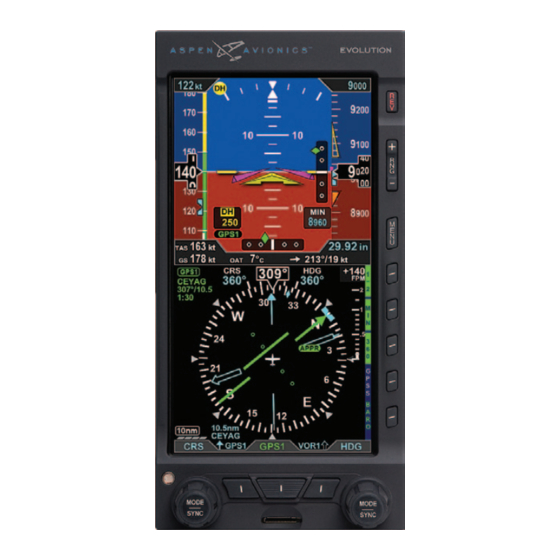
Aspen Avionics Evolution EFD 1000 C3 Pro PFD Manuals
Manuals and User Guides for Aspen Avionics Evolution EFD 1000 C3 Pro PFD. We have
1
Aspen Avionics Evolution EFD 1000 C3 Pro PFD manual available for free PDF download: Pilot's Manual
Aspen Avionics Evolution EFD 1000 C3 Pro PFD Pilot's Manual (234 pages)
FLIGHT DISPLAY
Brand:
Aspen Avionics
| Category:
Monitor
| Size: 16 MB
Table of Contents
Table of Contents
5
Table of Contents
15
Copyrights, Trademarks and Patents
21
Approvals
22
European Technical Standard Orders
22
Technical Standard Orders
22
LIMITED WARRANTY Aspen Avionics, Inc
23
Conventions
27
Terminology
27
Color Philosophy
29
Warnings, Cautions, and Notes
30
Example Graphics
31
Pilot Familiarity
31
Information Covered in this Pilot's Guide
32
Chapter 1 Welcome and Introduction
33
Figure 1-2 Single Display EFD1000 PFD System
34
System Overview
36
Primary Flight Display Unit (PFD)
37
Analog Converter Unit (ACU)
38
Configuration Module (CM)
38
Remote Sensor Module (RSM)
39
Chapter 2 Controls and Display
41
Controls & Display Orientation
42
Controls
44
Left and Right Knobs
44
Left Knob Functions
45
Right Knob Functions
45
Knob SYNC Function (Figure 2-3)
46
SYNC Function
46
Table 2-2 Left and Right Knob SYNC Description
47
Navigation Source Select Buttons
48
Using the Knobs (Example)
48
CDI Nav Source Select Button
49
Bearing Pointer Source Select Buttons
50
Hot Keys
51
Figure 2-9 Hot Key Menu 2 of
53
Menu
54
Using the Menus
54
Figure 2-16 Menu Edit Mode
55
Figure 2-18 Menu Text - Editable
56
Figure 2-23 EDIT VALUE Displays above Right Knob
57
Display Lighting
58
Range Buttons
59
REV Button
59
Display
60
Cleaning the Display Screen
61
Attitude Display
62
Attitude Director Indicator (ADI)
64
Airspeed Tape and Bug
65
2.A. Mach Number Display for Mmo Aircraft
66
Altitude Tape, Altitude Alerter, and
67
Instrument Approach Indicators
68
Data Bar
69
Navigation Display
70
Figure 2-35 Navigation Display Components
71
Compass Modes: 360º Vs. ARC
72
Direction Indicator (Magnetic Compass)
72
Ground Track Marker
73
Navigation Information
73
Course Pointer and
74
Horizontal Situation Indicator (HSI)
74
Auto Course Select
75
Deviation off Scale Indication
75
Bearing Pointers
76
Rate of Turn Indicator
77
Vertical Speed Indicator (VSI)
77
Situational Awareness Map
78
Chapter 3 Flying the PFD
79
Table 3-1 Basic EFD1000 Settings
80
Quick Controls Overview
81
Example Flight Scenario
83
Pre-Departure (Startup)
84
Figure 3-4 CDI Source Slashed Invalid
85
Figure 3-8 Selected Heading Field Enabled
87
Figure 3-10 CDI Navigation Source Selection Button
88
Figure 3-13 Changing the Map Declutter Level
89
Figure 3-14 Range Button
90
Figure 3-17 Traffic Overlay on
91
Figure 3-18 Altitude Bug Enabled
92
Figure 3-21 Selected Airspeed Field Enabled
93
Departure
94
Enroute
96
Figure 3-28 GPSS Enabled Legend in Green
97
Figure 3-30 360° Compass Mode
98
Arrival and Approach to Landing
99
GPSS Enabled
100
Showing Glide Slope
103
Chapter 4 Reference Guide
105
Air Data, Attitude and Heading Reference System (ADAHRS)
106
Attitude
107
Pitot Obstruction Monitor
108
Heading
109
Free Gyro Mode
110
Degraded ADAHRS Performance
111
Attitude Display
112
Attitude Indicator
112
Flight Director
113
Pitch Scale
113
Roll Scale
113
Slip/Skid Indicator
113
Airspeed Indicator
114
Ground Speed >50Kts Annunciation
115
Selected Airspeed
116
Airspeed Display
117
MACH Number Display for Mmo Aircraft
118
Altimeter
119
Barometric Units of Measure
120
Selected Altitude Field
121
Altitude Level-Off and Deviation Alert
122
MINIMUMS Annunciation
123
And Markers Disabled
124
Set Altitude Minimum
125
Figure 4-30 Selected MINIMUMS Field - MIN Enabled
125
Radio Altitude Display
126
Enable or Disable the Radio Altitude Display
126
Altitude Display
127
Data Bar
128
True Airspeed or Mach Number (When Enabled)
128
Ground Speed
129
Outside Air Temperature (When Enabled)
129
Select the Transition Setting
129
Set OAT Units of Measure
129
Barometric Pressure Setting Display
130
Wind Speed, Direction and Arrow (When Enabled)
130
Navigation Display
131
360° Compass Mode
132
ARC Compass Mode
132
Compass
132
Select ARC CDI/HSI Compass Mode
133
Figure 4-46 360/ARC Hot Key
134
Select Compass Type
134
Course Pointer
135
TO/FROM Indicator
136
Course Deviation Indicator and Scale
137
CDI Navigation Source
138
Localizer Back Course (BC) Operation
138
Select the CDI Navigation Source
139
Table 4-4 VHF NAV Radio Modes
140
Auto Course
142
Enable Auto Course
142
CDI Selected Course
143
Disable Auto Course
143
Select CDI Course
143
Bearing Pointer Source Selection
144
Select the Double-Line Bearing Pointer Source
146
Heading Bug
147
Set Heading Bug
147
Aircraft Heading Display
148
Rate of Turn Indicator
148
Basemap Overlays
149
Basemap Declutter and Range
150
Change Map Range
150
Select Map Declutter Level
150
Select the Single-Line Bearing Pointer Source
146
Activate Auto Range
151
Deactivate Auto Range
151
Flight Plan
152
Map Data Source and Reversion
152
Course Pointer Operation with Integrated Vor/Localizer/Gps Navigation Systems
153
GPS OBS Operation with a PFD and a Mechanical Standby Nav Indicator
153
Ground Track Marker
153
Enable Auto Range
151
Lateral and Vertical Deviation Indicator
154
Lateral Deviation Indicator
154
Vertical Deviation Indicator
155
Vertical Speed Indicator
156
Autopilot Integration
157
GPS Steering (GPSS)
158
Enable/Disable GPSS
159
Flight Director
162
Typical Autopilot Operations
162
HDG Mode Operation - GPS Steering (GPSS)
163
HDG Mode Operation - Heading Bug Steering
163
NAV Mode Operation - VLOC Navigation
163
NAV Mode Operation - GPS Navigation
164
APPR Mode Operation - ILS Approach with Vectors to Final
165
GPS/RNAV APV WAAS Approach
166
GPS APPR Mode Operation - WAAS GPS Underlay to ILS Approach Using Pilot Navigation and GPSS
167
Hazard Awareness
168
GPS APPR Mode Operation - WAAS GPS Underlay to ILS Approach with ATC Vectors to Final
168
Display the Traffic Overlay
169
Traffic Overlay
169
Traffic Symbols
170
Change the Traffic Altitude Filter
172
Traffic Altitude Filter
172
Traffic Unavailable
173
Chapter 5 Customizing the PFD
175
Menu Overview
175
Table 5-2 Menu – GENERAL SETTINGS B
176
Table 5-3 Menu – 360° MAP SETTINGS
177
Table 5-4 Menu – ARC MAP SETTINGS
178
Table 5-5 Menu – VSPEEDS a
179
Table 5-7 Menu – POWER SETTINGS
180
Table 5-8 Menu – SYSTEM STATUS
181
Customizing Basemap Symbol Declutter Settings
182
Figure 5-12 360° Airports Display Option Set to off
183
Set Map Symbol Display
183
Figure 5-13 Level 4
184
Configuring Vspeeds
185
Figure 5-18 Speed Bands
187
Display or Hide the Vspeed Textual Markers
188
Figure 5-20 Editing VSPEEDS
188
Figure 5-23 Editing Va Vspeed
189
Adjust Display Brightness Manually
190
Change Brightness Mode
190
LCD Brightness Control
190
Chapter 6 Expanded Emergency and Abnormal Procedures
191
Set Textual Vspeed Labels
189
Pitot/Static System Blockage
192
Blocked Pitot or Static Line Suspected
193
Identifying and Handling Suspected Pitot And/Or Static System Failures
194
Compare Alternate Sources of Available Attitude, Airspeed, and Attitude
197
Cross Check Attitude
197
CROSS CHECK ATTITUDE Annunciation
197
Difference Detected between the PFD and
197
Frequent or Persistent
197
Mechanical Attitude Indicators
197
Abnormal Shutdown Procedure
198
Power on Manually
198
Shutdown PFD (on Ground)
198
Loss of Aircraft Electrical Power
199
Loss of or Degraded Aircraft Power or on BAT Annunciation
199
GPS Failures and RSM Emergency GPS Use
201
Restore Aircraft Power to the PFD
201
Power Override
203
View External Voltage Status
203
View Internal Battery Status
203
In-Flight AHRS Reset
204
Figure 6-7 AHRS Reset Menu Key
205
GPSS Operation, Annunciations, and Autopilot Modes
206
Perform an In-Flight AHRS Reset
205
Disable GPSS
207
Figure 6-11 GPSS Disabled
207
Warning, Caution, and Advisory Summary
208
Figure 6-18 Cross Check Attitude
210
Figure 6-24 GPS Integrity Flag
211
Figure 6-27 GPSS Source Lost/Changed
212
Figure 6-29 REV Button off
213
Figure 6-31 GPS Annunciations
214
When GPSS Automatically Changes to Wings Level Mode
207
Chapter 7 Appendices
215
Operating Limitations
215
Software Versions and Serial Number
215
View the Input/Output Processor Software Version
216
Primary Flight Display Unit (PFD)
217
Specifications
217
Analog Converter Unit (ACU)
219
Remote Sensor Module (RSM)
219
Operational Specifications
220
Glossary
221
Index
225
View the Main Application Processor Software Version
216
Advertisement
Advertisement
Related Products
Aspen Avionics Evolution EFD 1000 MFD
Aspen Avionics Evolution EFD 500 MFD
Aspen Avionics Evolution EFD1000 PFD
Aspen Avionics EFD1000H PFD
Aspen Avionics Evolution Backup Display EFD1000C3
Aspen Avionics EFD1000 Dual EFI
Aspen Avionics EFD1000 E5
Aspen Avionics EFD 1000 PRO PFD
Aspen Avionics EFD1000 Pilot
Aspen Avionics Evolution Backup Display EFD500
Aspen Avionics Categories
Avionics Display
Autopilot System
Monitor
GPS
More Aspen Avionics Manuals
Login
Sign In
OR
Sign in with Facebook
Sign in with Google
Upload manual
Upload from disk
Upload from URL