Sign In
Upload
Manuals
Brands
Artison Manuals
Network Hardware
75340-1
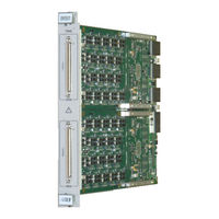
Artison 75340-1 Manuals
Manuals and User Guides for Artison 75340-1. We have
1
Artison 75340-1 manual available for free PDF download: User Manual
Artison 75340-1 User Manual (482 pages)
Brand:
Artison
| Category:
Network Hardware
| Size: 11 MB
Table of Contents
Table of Contents
6
Chapter 1
36
Introduction
36
Overview and Features
36
Driver/Receiver Board Options
39
Utility Resource (UR) Option
41
Basic Elements of the DRM System
41
Front Panel
42
Figure 1-1: Example DRM with Two Driver/Receiver Boards (DRA and DRB)
42
Figure 1-2: DRM Digital Resource Module Block Diagram
43
Figure 1-3: T940 Optional Front Panel PWR Connector
43
Power Converter (PC)
44
Digital Board (DB)
44
Data Sequencer a and B
44
Inter-Module Control
44
VXI Bridge
44
Driver/Receiver (DR) Board
44
Driver/Receiver Board a (DRA)
44
Driver/Receiver Board B (DRB)
45
Model and Part Number Information
45
Accessories
47
Chapter 2
48
Installation
48
Figure 2-1: T940 with Two DR7 Boards Installed
48
Initial Digital Board (DB) Switch Setting
49
Figure 2-2: T940 with Two Dr3E Boards Installed
49
Figure 2-3: Digital Board (DB) Switch Locations
50
Logical Address Selection
50
Table 2-1: Logical Address Selection
50
A24/A32 Map Selection
51
Table 2-2: VXI Interrupt Selection
51
Table 2-3: A24/A32 Map Selection
51
VXI Interrupt Selection
51
Other Settings
52
Debug Selection
52
Mode Selection
52
Table 2-4: Debug Selection
52
Table 2-5: Mode Selection
52
Bus Request Selection
53
DRS Inter-Module Mode Control
53
Table 2-6: Bus Request Selection
53
Figure 2-4: T940 Inter-Module Mode Jumper Connector Location
54
Figure 2-5: T940 Inter-Module Mode Jumper Positions and Settings
54
Installing the Module into a VXI Chassis
54
Figure 2-6: Installing the DRM into a Chassis
55
Figure 2-7: 1263 Series VXI Chassis (1263Hpf Top, 1263Hpr Bottom)
56
Initial Power-On
57
Software Installation
57
Vxiplug&Play Instrument Driver
57
Installing the Instrument Driver
58
Chapter 3
60
DRM Front Panel
60
Figure 3-1: T940 Front Panel (Appearance Typical)
60
Figure 3-2: T940 Front Panel (Showing Optional Front Power Connector)
61
J200 and J201 DRA Channel I/O
61
PWR Connector - DRA/DRB Power and Signals
61
Figure 3-3: PWR Connector
62
Front Panel Connectors
62
Table 3-1: PWR Connector Pinout
62
Table 3-2: Mating Connector Part Numbers
62
Table 3-3: Cable Assembly Part Numbers
62
Front Panel LBUS Lockout Keys
63
Figure 3-4: LBUS Lockout Keys
63
Figure 3-5: LBUS Lockout Configuration
64
LBUS Lockout Key Installation
64
Chapter 4
66
Functional Description
66
Digital Board (DB)
66
Figure 4-1: T940 DRM Block Diagram
66
Power Converter
67
Figure 4-2: T940 VXI Bridge Block Diagram
67
Type 1 and Type 3
68
Type 4
68
VXI Bridge
67
Description
67
Terms Used in this Section
67
Inter-Module Control
68
Table 4-1: Power Converter Type 1 and Type 3 Ranges
68
Table 4-2: Power Converter Type 004 Ranges
68
Figure 4-3: T940 Inter-Module Control Block Diagram
69
Terms Used in this Section
69
Description
70
T940 Inter-Module Mode Settings
70
Examples
72
Data Sequencer
75
Figure 4-4: Data Sequencer Block Diagram
75
Terms Used in this Section
76
Figure 4-5: Sequencer Logic Block Diagram
78
Master Clock
78
Sequence Logic
78
Counter/Timer & Pulse Generator
79
Probe/Flag RAM
79
Record Control
79
Sequence Controller
79
System Clock
79
Test Logic
79
Timers
79
Trigger Logic
79
AUX & Probe Control
80
Channel Control
80
Frequency Synthesizer
80
Pattern RAM
80
Record RAM
80
Sequence Control
80
Driver/Receiver
81
Chapter 5
82
Soft Front Panel Operation
82
SFP Basics
82
SFP Main Panel
83
Figure 5-1: Reset Screen
83
Figure 5-2: Initialize Warning
83
Figure 5-3: Main Panel
84
Figure 5-4: Main Panel UR14
84
Active LED
85
Chassis Data
85
Company Logo
85
Figure 5-5: Company Information Panel
85
Module Data
85
Title Bar
85
SFP Main Panel Menu Bar
86
Figure 5-6: Menu Bar
86
Figure 5-7: File Menu
86
File Menu
86
Table 5-1: File Menu Descriptions
86
Config Menu
87
Figure 5-8: Config Menu
87
Table 5-2: Config Menu Descriptions
87
Edit Menu
88
Execute Menu
88
Figure 5-10: Execute Menu
88
Figure 5-9: Edit Menu
88
Table 5-3: Edit Menu Descriptions
88
Table 5-4: Execute Menu Descriptions
88
Figure 5-11: Instrument Menu
89
Figure 5-12: Help Menu
89
Help Menu
89
Instrument Menu
89
Table 5-5: Instrument Menu Descriptions
89
Opening a VXI DRM Session
90
Figure 5-13: about DRM Driver Screen
90
Table 5-6: Help Menu Descriptions
90
Configuring the Global Hardware Parameters
91
Configure Module Panel
91
Figure 5-14: Opening a VXI DRM Session
91
Figure 5-15: Configure Module Panel
92
Inter-Module Mode
92
Table 5-7: Inter-Module Types
92
Table 5-8: Inter-Module Mode Settings
93
Linked Trigger Bus
94
Power Converter
94
Table 5-9: Power Converter Ranges
94
Figure 5-16: Configure Linked Trigger Bus Panel
95
Ltbn Signal
95
Table 5-10: LTB Signal Pull-Down Settings
95
Direction
96
Figure 5-17: Configure Group Panel
96
Group
96
Group Attributes
96
Invert
96
Table 5-11: Direction Settings
96
IO Max
97
IO Min
97
Offset
97
Slew
97
Table 5-12: Group Offset Attribute Settings
97
OC Sink
98
OC Src
98
Table 5-13: Group Slew Attribute Settings
98
Update Group Settings
98
Delay
99
Delay Signal
99
Group [1
99
Table 5-14: Delay Signal Settings
99
VXI Triggers
99
Figure 5-18: Set VXI Triggers DSA Panel
100
Table 5-15: Signal Pull-Down Settings
100
TTLTRG and ECLTRG Signal
100
D/R Properties
101
Invert
101
Dut_Gnd
102
Figure 5-19: Configure Dsn D/R Properties Panel
102
Table 5-16: Voltage Mode Settings
102
Voltage Mode
102
MFSIG Source
103
MPSIG Signal
103
Table 5-17: MFSIG Settings
103
Table 5-18: MPSIG Source
103
Error Pulse Width
104
Record Mode
104
Table 5-19: Error Pulse Width Settings
104
Config Data Sequencer A/B
105
Configure Clocks
105
Figure 5-20: Configure Data Sequencer
105
Table 5-20: Record Mode Settings
105
Figure 5-21: Configure Clocks
106
Master Clock
106
Table 5-21: Master Clock Source Settings
106
External Mode
107
System Clock
107
Table 5-22: System Clock Source Settings
107
Table 5-23: External Mode Settings
107
External Offset
108
Synthesizer Freq (Mhz)
108
Synthesizer Ref Source
108
Reference Freq (Mhz)
108
Table 5-24: Synthesizer Ref Source Settings
108
Configure Timers
109
Figure 5-22: Configure Timers
109
Table 5-25: Watchdog Action
110
Watchdog Action
110
Pattern Timeout
111
Sequence Timeout State
111
Sequence Timeout Time
111
Table 5-26: Watchdog Timer Resolution Ranges
111
Table 5-27: Sequence Timeout State Action
111
Watchdog Time
111
Pattern Delay 1-2
112
Configure Triggers
112
Figure 5-23: Configure Triggers Panel
112
Source
113
Table 5-28: Trigger Settings
113
Trigger
113
Table 5-29: Trigger Source Settings
114
Table 5-30: Trigger Test Condition Settings
114
Test Condition
114
Edge Test Clear
115
Input Mode
115
Table 5-31: Trigger Input Mode Settings
115
Table 5-32 Trigger Event Clear Settings
115
Configure Pulse Generator
116
Resolution
116
Mode
116
Figure 5-24: Configure Pulse Generator
116
Step
117
Period
117
Delay
117
Table 5-33: Pulse Generator Mode Settings
117
Width
118
Configure Data Sequencer Settings
118
Error Record Basis
119
Raw Record Basis
119
Record Offset
119
Figure 5-25: Data Sequencer Configure Settings Panel
119
Table 5-34: Error Record Basis Settings
119
Table 5-35: Raw Record Basis Settings
119
Record Type
120
Error Count Basis
120
Table 5-36: Record Type Settings
120
Table 5-37: Error Count Basis Settings
120
Error Address Basis
121
Timing Mode
121
Table 5-38: Error Address Basis Settings
121
Table 5-39: Timing Mode Settings
121
Output-To-Input Disable
122
Pass Fail Basis
122
Table 5-40: Output-To-Input Disable Settings
122
Table 5-41: Pass Fail Basis Settings
122
Pass Valid Mode
123
Table 5-42: Pass Valid Mode Settings
123
Over-Current
124
Channel and Global Disable
124
Figure 5-26: Over-Current Panel
124
Over-Current Window
124
Drive Fault
125
Table 5-43: Over-Current Window Settings
125
Probe
126
Figure 5-27: Probe Panel
126
Probe State
126
Table 5-44: Drive Fault Settings
126
CRC Capture
127
Offset
127
Probe Data
127
Table 5-45: Probe Data Settings
127
Table 5-46: CRC Capture Settings
127
Probe Button
128
Probe Button Level
128
Probe Input Compare High and Low
128
Probe Input Connect
128
Table 5-47: Probe Button Settings
128
Compensation
129
Probe Cal Connect
129
Probe Cal Signal
129
Probe Output Connect
129
Table 5-48: Probe Cal Signal Settings
129
DC Cal
130
Attributes
131
Figure 5-28: Attribute Panel
131
Jump Pass Fail
131
Phase 3 Mode
131
Table 5-49: Jump Pass Fail Settings
131
CRC Preload
132
Table 5-50: Phase 3 Mode Settings
132
Table 5-51: Window 3 Mode Settings
132
Window 3 Delay
132
Window 3 Mode
132
CRC Algorithm and Capture Mask
133
Static State
133
Table 5-52: CRC Preload Settings
133
Table 5-53: CRC Algorithm and Mask Settings
133
Configuring the I/O Channels
134
Figure 5-29: Configure Channels Panel
134
Selecting the Channels
134
Table 5-54: Static State Settings
134
Channel Parameters
135
Stimulus Signal
135
Table 5-55: Stimulus Signal Settings
135
Stimulus Format
136
Table 5-56: Stimulus Format Settings
136
Capture Signal
137
Capture Mode
138
Static Mode
138
Table 5-57: Capture Signal Settings
138
Table 5-58: Capture Mode Settings
138
Configure Channel Properties
139
Properties
139
Table 5-59: Static Mode Settings
139
Driver Levels
140
Figure 5-30: Configure Channel Properties Panel
140
Comparator Levels
141
Driver Slew
141
Table 5-60: Slew Settings
141
Termination
141
Active Load
142
Over-Current Alarm Levels
142
Table 5-61: Active Load Settings
142
Figure 5-31: Current Load
143
Figure 5-32: Resistive to VCOM Load
143
Table 5-62: Resistive Settings
143
Channel Connect
144
Comparator Delay
144
Hybrid Connect
144
Table 5-63: Channel Connect Settings
144
Channel Mode
145
Configure UR14 Channel Properties
145
All Channels
146
Compare Input (V)
146
OC Detect (A)
146
Configuring the aux Channels
146
Figure 5-33: Configure UR14 Channel Properties Panel
146
Figure 5-34: Configure aux Channels Panel
147
Figure 5-35: Configure aux Channels Panel UR14
147
Table 5-64: Drn aux Configuration
148
Table 5-65: UR14 aux Configuration
148
Configuring the AUX/UAUX Signals
149
Figure 5-36: Shared AUX/UAUX Controls
149
Source
150
State
150
Table 5-66: aux Output State Settings
150
Table 5-67: aux Source Settings
150
Input Bus Source
151
Table 5-68: Input Bus Select Source Settings
151
Connect State
152
ECL Mode (ECL Differential or Bipolar Logic)
152
Logic Mode (Lvttl/Bipolar ECL Logic)
152
Properties (Programmable Logic)
152
Table 5-69: ECL Mode Settings
152
Configuring the Interrupts
153
Table 5-70: Logic Mode Settings
153
Condition
154
Event
154
Event False
154
Event True
154
Figure 5-37: Configure Interrupt
154
Editing the Data Sequencers
155
Editing the Timing Sets
155
Figure 5-38: Editing the Data Sequencers
155
Figure 5-39: Phase Timing
155
Figure 5-40: Data Sequencer Timing Sets Panel
156
Advanced Timing Set Features
157
Timing Set Value Rules
157
Idle/Standby Timing
158
Phase/Window Spanning
158
Editing the Patterns
158
Append
159
Figure 5-41: Edit Patterns Panel
159
Assign
160
Figure 5-42: Append Data Sequencer Pattern Sets Panel
160
Edit Data
161
Figure 5-43: Assign Data Sequencer Pattern Sets Panel
161
Figure 5-44: Pattern Set Sequencer Data Panel
162
Figure 5-45: Pattern Set Data - View Menu
162
Figure 5-46: Goto Pattern Panel
163
Figure 5-47: Pattern Codes
163
Figure 5-48: Probe Codes
164
Table 5-71: Probe Expect Codes
165
Figure 5-49: Pattern Set Data - File Menu
167
Table 5-72: Pattern Codes
167
ASCII Hex
168
Data Format
168
Header Format
168
Import/Export File Format
168
Table 5-73: Ascii/Binary Data Format
169
Binary
170
Table 5-74: Binary Block Format
170
ASCII String
171
Editing Waveforms
171
Table 5-75: Waveform Table Size Settings
173
Waveform
173
Waveform Definition
173
Editing Sequence Parameters
174
Figure 5-52: Data Sequencer Parameters Panel
174
Lc0 - Lc15
174
Pipeline
175
Table 5-76: Vector Strobe Settings
175
Vector Strobe
175
Figure 5-53: Edit Vector Bits Panel
176
Set Vector Bits
176
Source
176
Input Mode
177
Set Vector Table
177
Table 5-77: Vector Bit Source Settings
177
Table 5-78: Vector Bit Input Mode Settings
177
Figure 5-54: Edit Vector Table Panel
178
Set Channel Test
178
Timing Set
178
Vector Bit Index
178
Vector Jump Step
178
Expect
179
Figure 5-55: Sequencer Channel Test Panel
179
Mask
179
Editing Sequence Steps
180
Figure 5-56: Edit Sequence Step Panel
180
Clocks Per Pattern
181
Figure 5-57: Sequence Step Data Panel
181
Internal T0CLK
181
CPP Phase and Window Triggering
182
Timing Set
182
Gosub Return
183
Jump Type
183
Last Step
183
Sequence Flag 1 and Sequence Flag 2
183
Sequence Timeout
183
Jump Condition
184
Jump Step
184
Table 5-79: Jump Condition Settings
184
Table 5-81: Jump Type Settings
184
Loop Count
185
Loop Counter
186
Pass Fail Clear
186
Step Record Mode
186
Table 5-80: Step Record Mode Settings
186
Vector Jump
186
Table 5-81: Step Record Mode Settings
187
Timing
187
Figure 5-58: Edit Timing Set Panel
188
Patterns
188
Figure 5-59: Initialize Step Pattern Set Panel
189
Figure 5-60: Edit Pattern Set Panel
189
Figure 5-61: Sequence Step Properties Panel
190
Handshake Control
190
Pause Signal
190
Properties
190
Table 5-82: Handshake Pause Signal
190
Resume Modifier
191
Phase Trigger Properties
192
Table 5-83: Handshake Modifier Settings
192
Waveform Properties
192
Waveform Table
192
Waveform1 - Waveform4
192
Execute the Sequence
193
Figure 5-62: Executing a Sequence Panel
193
Execution Overview
194
Figure 5-63: Execute State Diagram
194
Table 5-84: Execute State Description
194
Table 5-85: Execute State Transition Description
195
Active LED
196
Execute Panel Indicators
196
Idle LED
196
Burst Error LED
197
D/R Alert
197
Errors
197
Halt LED
197
Pause LED
197
Power Converter Alert
197
Pattern Address
198
Record Count
198
Sequence Active
198
Step Number
198
Timing Set
198
Execute Panel Modes and Settings
198
Start/Arm Selector
198
Channel Drivers
199
Execute Idle Step
199
Table 5-86: Channel Drivers Settings
199
Burst
200
Execute Step
200
Halt Mode
200
Table 5-87: Halt Mode Settings
200
Finish Mode
201
Finish Mode Step
201
Table 5-88: Finish Mode Settings
201
CRC Type
202
Set Sync
202
Stop Mode
202
Table 5-89: Stop Mode Settings
202
Table 5-90: CRC Type Settings
202
Event (and Step)
203
Figure 5-64: Set Sync Panel
203
Offset
203
Sync Number
203
Table 5-91: Finish Mode Settings
203
Length
204
Execute Panel Command Buttons
204
Execute
204
Execute Idle
204
Halt
204
Arm PG
205
Deskew
205
Master Reset
205
Reset
205
Resume
205
Stop
205
Stop PG
206
Analyze the Execution Results
206
Static Data
206
Figure 5-65: Execute DSA View Menu
206
Figure 5-66: Static Data Panel
207
Response Delay
207
Stimulus Delay
207
Response
208
Stimulus
208
Kept Data
208
Table 5-92: Static Stimulus Settings
208
Table 5-93: Static Stimulus Settings
208
Results
209
Figure 5-67: Kept Data Panel
209
CRC Save File Format
210
Figure 5-68: View Results Data Panel
210
Save Results
210
Table 5-94: Results View Settings
210
View
210
Error Address Save File Format
211
Record Data Save File Format
211
Record Index Save File Format
211
Crcs Display
212
Figure 5-69: View CRC Panel
212
Probe Data Save File Format
212
Error Address Display
213
Figure 5-70: View Errors Address Panel
213
Figure 5-71: Execution Results View Menu
214
Figure 5-72: View Errors Address Panel Hex
214
Record Index Display
214
Figure 5-73: Record Index Panel
215
Record Data Display
215
Figure 5-74: View Record Data Panel
216
Probe Data Memory Display
216
Figure 5-75: Probe Data Panel
217
Table 5-95: Probe Memory Bit Descriptions
217
Sequencer Events
220
Status Indicator Panels
220
Figure 5-76: Sequencer Event Status Panel
221
Table 5-96: Sequence Enable/Condition/Event Bit Descriptions
221
Clear Event
223
Condition
223
Enable
223
Event
223
Sequencer Data Panel
223
Counter Active
224
Figure 5-77: Sequencer Data DSA Panel
224
Record Index Count
224
Sync Error Pattern Address
224
Sync Error Step
224
Driver/Receiver Events Panel
225
Status
225
Table 5-97: Sequence Status Bit Descriptions
225
Figure 5-78: DR3E/DR9/UR14 Driver/Receiver (D/R) Events Panel
226
Table 5-98: Sequence Status Bit Descriptions
226
Figure 5-79: DR4 Driver/Receiver (D/R) Events Panel
227
Table 5-99: Sequence Status Bit Descriptions
227
Alert Text
228
Clear Event
228
Condition
228
Enable
228
Event
228
Driver/Receiver Data Panel
229
Table 5-100: Alert Bit Descriptions
229
Figure 5-80: Driver/Receiver Data Panel
230
Figure 5-81: VXI Trigger Readback Panel
231
Query Power Results Message
231
VXI Trigger Readback Panel
231
Figure 5-82: Query Power Results Message
232
Figure 5-83: Power Converter Condition Panel
232
Power Converter Condition Panel
232
Counter/Timer Panel
233
Figure 5-84: Timer/Counter Panel
233
Function
233
Input <1-3> Source
234
Table 5-101: Counter/Timer Function Settings
234
Table 5-102: Counter/Timer Input <1-3> Source
234
Aperture
235
Input <1-3> Slope
235
Table 5-103: Counter/Timer Input <1-3> Slope
235
Table 5-104: Counter/Timer Aperture
235
Trigger
235
Figure 5-85: PMU Panel
236
Initiate
236
PMU Panel
236
Results
236
Table 5-105: Timer/Counter Trigger Source
236
Channel
237
Measure Voltage
237
Instrument Functions
237
Figure 5-86: Self Test Result Message
237
Self Test
237
Table 5-106: Self Test Result Code Descriptions
238
Figure 5-87: Full RAM Test Results Panel
239
Full RAM Test
239
Power Converter Test
239
Calibration Panel
240
Figure 5-88: Power Converter Test Results Panel
240
Table 5-107: Power Converter Test Thresholds
240
Calibrate Function
241
Driver/Receiver
241
Figure 5-89: Calibration Confirmation Panel
241
Figure 5-90: Calibration Panel
241
Meas. Delay
242
Serial Number
242
Start Chan
242
Table 5-108: Calibrate Function Settings
242
End Channel
243
Figure 5-91: Confirm Calibrate Panel
243
Figure 5-92: Calibrate Warm-Up Panel
243
Run
243
Figure 5-93: Calibrate Run Panel
244
Verify
244
Figure 5-94: Confirm Verify Panel
245
Figure 5-95: Verify Select Directory Panel
245
Figure 5-96: Verify Warm-Up Panel
246
Figure 5-97: Verify Run Panel
246
Export
247
Figure 5-98: DB Monitor Temperature Panel
247
Monitor Temperature Panel
247
Stop
247
Trip Temperature
247
Update
247
Figure 5-99: Dr3E Monitor Temperature Panel
248
Figure 5-100: DR9 Monitor Temperature Panel
249
Figure 5-101: UR14 Monitor Temperature Panel
249
Figure 5-102: DR3E, DR9 and UR14 Voltage Monitoring Panel
250
Voltage
250
Voltage Monitor Panel
250
Channel
251
Extforce
251
Extsense
251
Front Panel DUT_GND
251
Monitor Signal
251
V- Voltage
251
Channel
252
DR4 Voltage Monitor Panel and Controls
252
Figure 5-103: DR4 Voltage Monitoring Panel
252
Monitor Voltage
252
Mux Signal
252
AD Signal
253
CD Signal or E_S Signal
253
Mode
253
Negative Signal
253
Positive Signal
253
Register
253
Chip Temperature Panel
254
Figure 5-104: Dr3E Chip Temperature
254
Value
254
Figure 5-105: DR9 Chip Temperature
255
Figure 5-106: UR14 Chip Temperature
255
Utility Reference Monitor
255
Figure 5-107: Utility Reference Monitor
256
Monitor Signal
256
Table 5-109: UR14 Monitor Signal Settings
256
Figure 5-108: SFP Close Message
257
Figure 5-109: SFP Reset Message
257
SFP Close Message
257
Chapter 6
258
Programmable Channel Calibration
258
Performance Verification
258
Table 6-1: Calibration Functions and DRM Requirement
258
Environmental Conditions
259
Voltage Mode
259
And V- Requirements
259
Warm-Up Period
259
Recommended Test Equipment
259
Table 6-2: Recommended Power Converter Settings
259
Basic Setup
260
Calibration Interval
260
Calibration Temperature
260
Table 6-3: Recommended Calibration Equipment
260
Calibration Procedures
261
Figure 6-1: Invoke the Calibrate DRM Panel from the SFP
261
ADC Reference (Via EXTERNAL FORCE)
262
Select Calibrate Function
262
Select Measurement Delay
263
Figure 6-2: T940-Dr3E-Dr3E Connection Diagram
264
Figure 6-3: T940-DR9-DR9 or T940-UR14 Connection Diagram
264
Run Calibration
264
Monitor + ADC
265
Select Calibrate Function
265
DRM Calibration Warmup
266
Select Start and End Channels and Measurement Delay
266
Run Calibration
267
Source/Sink Load
268
Run Calibration
268
Select Calibrate Function
268
Figure 6-4: T940-Dr3E-Dr3E Connection Diagram
269
Figure 6-5: T940-DR9-DR9 or T940-UR14 Connection Diagram
269
Dvh/Dvl
270
Select Calibrate Function
270
DRM Calibration Warmup
271
Run Calibration
271
Select Start and End Channels and Measurement Delay
271
Cvh/Cvl
272
Select Calibrate Function
272
DRM Calibration Warmup
273
Select Start and End Channels and Measurement Delay
273
Run Calibration
274
Vcom High/Low
275
Select Calibrate Function
275
Select Start and End Channels and Measurement Delay
275
DRM Calibration Warmup
276
Run Calibration
276
Source/Sink Load
277
Select Calibrate Function
277
DRM Calibration Warmup
278
Select Start and End Channels and Measurement Delay
278
Run Calibration
279
Ial/Iah
280
Select Calibrate Function
280
Select Start and End Channels and Measurement Delay
280
DRM Calibration Warmup
281
Run Calibration
281
Chapter 7
284
Specifications
284
Stimulus/Capture Characteristics
286
Recording Mode Characteristics
287
Sequencer Characteristics
288
Master Clock (MCLK)
290
Counter/Timer Characteristics
291
Pulse Generator Characteristics
292
Calibration
292
Front Panel I/O
293
VXI Interface
293
Table 7-1: Power Requirements (DB Only)
293
Environmental
294
Chapter 8
296
Advanced Topics
296
Jumping, Halting, Counting and Logging on Pass/Fail Conditions
296
Coupling Signals between Sequencers for Linking and DRS Formation
297
Figure 8-1: Configure Module Panel
298
Figure 8-2: Configure Module Panel
299
Figure 8-3: Configure VXI Triggers DSA Panel
300
Table 8-1: Summary of When Specific DRS Signals Are Needed
300
Step Record Mode
301
Figure 8-4: Step Record Mode Control on Edit DSA Sequence Step Panel
301
Figure 8-5: Setting the Record Mode Using the Configure Module Panel
302
Table 8-2: Summary of the Record Memory Action for each Step Record Mode
302
Record Type
303
Figure 8-6: Setting the Record Type Using the Configure DSA Settings Panel
303
Counting and Logging Errors
304
Table 8-3: Summary of the Record Memory Action for each Step Record Mode
304
Figure 8-7: Setting the Test Bit in the Edit DSA Pattern Set Step Panel
305
Figure 8-8: Setting Error Count Basis in the Configure DSA Settings Panel
306
Figure 8-9: Setting Error Address Basis in the Configure DSA Settings Panel
306
Table 8-4: Cross-Reference of Step Record Mode to Error Count Basis
307
Table 8-5: Cross-Reference of Step Record Mode to Error Address Basis
307
Pipelining and Non-Pipelining
308
Jumping and Halting on Pass/Fail
309
Figure 8-10: Setting the Pipeline Mask in the Edit DSA Parameters Panel
309
Figure 8-11: Setting the Pass/Fail Basis in the Configure DSA Settings Panel
310
Figure 8-12: Setting the Pass/Fail Basis in the Configure DSA Settings Panel
310
Table 8-6: Cross-Reference of Step Record Mode to Pass Fail Basis
311
Figure 8-13: Setting the Jump Condition in the Edit DSA Sequence Step Panel
312
Understanding Pass and Fail
313
Figure 8-14: Setting the Halt Mode in the Execute DSA Panel
313
Figure 8-15: Setting the Halt Mode in the Execute DSA Panel
314
Table 8-7: Truth Table Describing Pass and Fail
315
Figure 8-16: Setting the Pass Fail Clear Control in the Edit DSA Sequence Step Panel
316
Figure 8-17: Setting the Jump Pass Fail Mode in the DSA Advanced Options Panel
317
Additional Pipeline Information
318
Valid Pass and Capture Fault
319
Additional Halt Information
319
Figure 8-18: Setting the Halt Mode in the Execute DSA Panel
320
Pipelined Depth Calculation
321
Pause and Halt Capabilities
322
Definitions
322
Applications
322
CPU Halt/Single-Stepping/Resume Operations
322
External Halt Operations
323
Halt Examples
324
Halt Notes
325
Pause Operations
325
Pause Examples
327
Pause Notes
328
Sequencer Operation
329
Introduction
329
Pattern Control Instructions
330
Pattern Control Instruction Details
332
T964 VXI Backplane Trigger Bus
337
Trigger Bus Description
337
Trigger Bus Applications
337
Normal Operation
338
Normal Operation Example
338
Advanced Operation Examples
338
Notes
339
Appendix A
340
Glossary of Terms and Acronyms
340
Appendix B DR1 Driver/Receiver Board
346
Front Panel Connectors
346
Block Diagram
346
Auxiliary Driver & Receiver I/O
347
Figure B-1: DR1 Driver/Receiver Block Diagram
347
Figure B-2: Auxiliary Driver & Receiver I/O Block Diagram
348
Signal Descriptions
348
DR1 Driver & Receiver I/O
349
Signal Descriptions
349
Control Logic
349
Figure B-3: DR1 Driver & Receiver I/O Block Diagram
349
Signal Descriptions
350
Table B-1: DR1 Characteristics
350
Power Requirements
351
Environmental
351
Table B-2: DR1 Power Requirements
351
DRA I/O Channels (J200
352
Figure B-4: J200 and J201 Connectors
352
Table B-3: DR1, DRA I/O Channels (J200
352
Table B-4: DR1 Pinout by Pin Number (DRA
353
Table B-5: DR1, DRB I/O Channels (J201
354
Table B-6: DR1 Pinout by Pin Number (DRB
355
Figure B-5: Front Panel PWR Connector
356
Table B-7: PWR Connector
356
Calibration
357
Table B-8: Calibration Settings
357
Appendix C DR2 Driver/Receiver Board
358
DR2 Features
358
Front Panel Connectors
358
Block Diagram
358
Auxilliary Driver & Receiver I/O
359
Figure C-1: DR2 Driver/Receiver Block Diagram
359
Figure C-2: Auxiliary Driver & Receiver I/O Block Diagram
360
Signal Descriptions
360
DR2 Driver & Receiver I/O
361
Signal Descriptions
361
Control Logic
361
Figure C-3: DR2 Driver & Receiver I/O Block Diagram
361
Signal Descriptions
362
DR2 Characteristics
362
Table C-1: DR2 Characteristics
362
Environmental
363
Table C-2: DR2 Power Requirements
363
DR2 Signal Description
364
DRA I/O Channels (J200
364
Figure C-4: J200 and J201 Connectors
364
Table C-3: DR2, DRA I/O Channels (J200
364
Table C-4: DR2 Pinout by Pin Number (DRA
365
DRB I/O Channels (J201
367
Table C-5: DR2, DRB I/O Channels (J201
367
Table C-6: DR2 Pinout by Pin Number (DRB
368
PWR Connector
369
Figure C-5: Front Panel PWR Connector
369
Calibration
370
Table C-7: PWR Connector
370
Table C-8: Calibration Settings
370
Appendix D
372
Block Diagram
372
Auxiliary Driver & Receiver I/O
373
Figure D-1: Dr3E Driver/Receiver Block Diagram
373
Figure D-2: Auxiliary Driver & Receiver I/O Block Diagram
374
Signal Descriptions
374
Dr3E Driver & Receiver I/O
375
Signal Descriptions
375
Control Logic
375
Figure D-3: Dr3E Driver & Receiver I/O Block Diagram
375
Figure D-4: Dr3E Control Logic Block Diagram
377
Signal Descriptions
377
Firmware & NV Data
378
Signal Descriptions
378
Front Panel Connectors
372
Dr3E Characteristics
379
Table D-1: Dr3E Characteristics
379
Table D-2: Dr3E I/O Min/Max Levels Front Panel
380
Table D-3: Dr3E I/O Min/Max Levels Power Converter Type 1
381
Table D-4: VXI Power Requirements with Front Panel Power
381
Environmental
382
Dr3E Signal Description
383
Figure D-5: J200 and J201 Connectors
383
Table D-6: Dr3E, DRA I/O Channels (J200
384
Table D-7: Dr3E Pinout by Pin Number (DRA
385
Table D-8: Dr3E, DRB I/O Channels (J201
386
Table D-9: Dr3E Pinout by Pin Number (DRB
387
Figure D-6: Front Panel Optional Dr3E PWR Connector
388
Calibration
389
Table D-10: PWR Connector
389
Table D-11: Calibration Settings
389
Appendix E
390
Block Diagram
390
Figure E-1: DR4 I/O Block Diagram
391
Signal Descriptions
392
Figure E-2: DR4 Driver/Receiver Block Diagram
393
Signal Descriptions
393
Auxiliary Driver & Receiver I/O
394
Figure E-3: Auxiliary Driver & Receiver I/O Block Diagram
394
Figure E-4: DR4 Power Configuration
395
DR4 Features
390
Front Panel Connectors
390
DR4 Characteristics
396
Table E-1: DR4 Characteristics
396
Environmental
397
Table E-2: VXI Power Requirements
397
Power Requirements
397
DR4 Signal Description
398
Figure E-5: J200 and J201 Connectors
398
Table E-3: DR4, DRA I/O Channels (J200
398
Table E-4: DR4 Pinout by Pin Number (DRA
398
Table E-5: DR4, DRB I/O Channels (J201
400
Table E-6: DR4 Pinout by Pin Number (DRB
400
Calibration
401
Table E-7: Calibration Settings
401
Appendix F DR7 Driver/Receiver Board
402
DR7 Features
402
Front Panel Connectors
402
Block Diagram
402
Auxiliary Driver & Receiver I/O
403
Figure F-1: DR7 Driver/Receiver Block Diagram
403
Figure F-2: Auxiliary Driver & Receiver I/O Block Diagram
404
Signal Descriptions
404
DR7 Driver & Receiver I/O
405
Figure F-3: DR7 Driver & Receiver I/O Block Diagram
405
Signal Descriptions
405
Control Logic
406
Signal Descriptions
406
Firmware & NV Data
406
DR7 Characteristics
406
Table F-1: DR7 Characteristics
406
Power Requirements
407
Environmental
407
Table F-2: DR7 Power Requirements
407
DR7 Signal Description
408
DRA I/O Channels (J200
408
Figure F-4: J200 and J201 Connectors
408
Table F-3: DR7, DRA I/O Channels (J200
408
Table F-4: DR7 Pinout by Pin Number (DRA
409
DRB I/O Channels (J201
411
Calibration
411
Table F-5: DR7, DRB I/O Channels (J201
411
Table F-6: Calibration Settings
411
Appendix G DR8 Driver/Receiver Board
412
DR8 Features
412
Front Panel Connectors
412
Auxiliary Driver & Receiver I/O
413
Figure G-1: DR8 Driver/Receiver Block Diagram
413
Figure G-2: Auxiliary Driver & Receiver I/O Block Diagram
414
Signal Descriptions
414
DR8 Driver & Receiver I/O
415
Signal Descriptions
415
Control Logic
415
Figure G-3: DR8 Driver & Receiver I/O Block Diagram
415
Firmware & NV Data
416
Signal Descriptions
416
DR8 Characteristics
416
Table G-1: DR8 Characteristics
416
Power Requirements
417
Environmental
417
Table G-2: DR8 Power Requirements
417
DR8 Signal Description
418
DRA I/O Channels (J200
418
Figure G-4: J200 and J201 Connectors
418
Table G-3: DR8, DRA I/O Channels (J200
418
Table G-4: DR8 Pin out by Pin Number (DRA
419
DRB I/O Channels (J201
420
Table G-5: DR8, DRB I/O Channels (J201
420
Table G-6: DR8 Pin out by Pin Number (DRB
421
PWR Connector
422
Figure G-5: Front Panel PWR Connector
422
Table G-7: PWR Connector
422
Calibration
423
Table G-8: Calibration Settings
423
Appendix H DR9 Driver/Receiver Board
424
DR9 Features
424
Front Panel Connectors
424
Figure H-1: DR9 Front Panel Connectors
425
Block Diagram
426
Figure H-2: DR9 Driver/Receiver Block Diagram
426
Auxiliary Driver & Receiver I/O
427
Signal Descriptions
427
DR9 Driver & Receiver I/O
427
Figure H-3: Auxiliary Driver & Receiver I/O Block Diagram
427
Signal Descriptions
428
Control Logic
428
Figure H-4: DR9 Driver & Receiver I/O Block Diagram
428
Figure H-5: DR9 Control Logic Block Diagram
430
Signal Descriptions
430
Firmware & NV Data
431
Signal Descriptions
431
DR9 Characteristics
431
Table H-1: DR9 Characteristics
431
Table H-2: DR9 I/O Min/Max Levels Front Panel
433
Table H-3: DR9 I/O Min/Max Levels Power Converter Type 1
434
Table H-4: DR9 Power Requirements (Not Including Power Converter Power Consumption
434
Environmental
435
Figure H-6: DR9 J1A, J1B, J2A, J2B, J3A and J3B Signal Connectors
436
Table H-5: DRA Resources
437
Table H-6: J3A Connector Pinout by Pin Number
437
Table H-7: J2A Connector Pinout by Pin Number
437
Table H-8: J1A Connector Pinout by Pin Number
438
DRB Resources
439
Table H-9: DRB Resources
439
Table H-10: J3B Connector Pinout by Pin Number
439
Table H-11: 2B Connector Pinout by Pin Number
439
Table H-12: J1B Connector Pinout by Pin Number
440
Table H-13: J9A Pinout
441
Table H-14: J9B Pinout
441
Calibration
442
Appendix I UR14 Driver/Receiver Board
444
UR14 Features
444
Block Diagram
444
Figure I-1: UR14 Front Panel
445
Figure I-2: UR14 Driver/Receiver Block Diagram
446
Auxiliary Driver and Receiver I/O ECL/LVTTL
447
Figure I-3: Auxiliary AUX3 a & AUX[5:12] a LVTTL & DIFF ECL I/O
447
Signal Descriptions (Figure
448
Figure I-4: Auxiliary AUX[5:8] B LVTTL | SE ECL I/O
449
Figure I-5: Auxiliary AUX[9:12] B SE | DIFF ECL I/O
450
Figure I-6: Probe I/O Block Diagram
451
Probe I/O
451
Figure I-7: Programmable Driver and Receiver I/O
453
Open Collector Channels I/O
454
Figure I-8: Open Collector Channel I/O
455
Signal Descriptions (Figure
455
ADC Voltage and Temperature Monitoring
456
Figure I-9: ADC Voltage and Temperature Monitoring
456
External Probe Module Block Diagram
458
Firmware and Calibration Storage
458
UR14 Control Logic
458
External Probe Module
459
External Probe Module
461
Figure I-11: External Probe Module Flush Mount
461
Figure I-12: External Probe Module Right Angle
461
Figure I-13: External Probe Module with Probe
462
Table I-1: External Probe Module Characteristics
462
UR14 Characteristics
463
Utility Channels
463
Table I-2: Utility Channel Characteristics
463
Programmable Channels
464
Table I-3: Programmable Channel Characteristics
464
Table I-4: Programmable aux I/O Min/Max Levels Front Panel
466
Table I-5: Programmable aux I/O Min/Max Levels Power Converter Type 1
466
Adc_In
467
Probe Support
467
Figure I-10: External Probe Module
467
Table I-6: ADC_IN Characteristics
467
Table I-7: Probe Support
467
Table I-8: Probe Module Characteristics
467
Power Requirements
469
Table I-9: Auxiliary I/O Channel Characteristics
469
Table I-10: Power Requirements (Not Including Power Converter Power Consumption
469
Environmental
470
Table I-11: Environmental
470
UR14 Signal Description
471
Figure I-14: Front Panel Connectors
471
Table I-12: UR14 Resources
472
Ur14 I/O (J1A, J1B, J2A, J2B, J3A, J3B
472
Table I-13: J3A Connector Pinout by Pin Number
473
Table I-14: J3B Connector Pinout by Pin Number
474
Table I-15: J2A Connector Pinout by Pin Number
474
Table I-16: J3B Connector Pinout by Pin Number
475
Table I-17: J1A Connector Pinout by Pin Number
475
Table I-18: J1B Connector Pinout by Pin Number
475
Figure I-15: UR14 J9 Calibration and Signal Connectors
476
Calibration
477
Appendix J DRM Timing Characteristics
478
Introduction
478
External aux Input Timing Adjustments
478
External aux Output Timing Adjustments
479
TRG Input Timing Adjustments
479
TRG Output Timing Adjustments
479
AUX Input to TRG
479
TRG Input to aux Output
479
DRS Timing Adjustments
479
External T0CLK to T0CLK in (at Min. Delay Setting
479
External Halt Setup Time to SEQ_CLK out
480
External Pause to CLK Cease
480
External Pause/Phase Resume to CLK Resume
480
External Jump Setup Time to T0CLK in
480
External Start Setup Time to T0CLK in
481
External Stop Setup Time to T0CLK in
481
A Channel Input to TRG Bus (for a Channel Test
481
Seq_Act/Idle_Act/Sync Pulse/Seq. Flag to TRG Bus
481
Advertisement
Advertisement
Related Products
Artison Astronics Talon Instruments T940 64-Channel Digital Resource Module
Artison Categories
Speakers
Subwoofer
Amplifier
Switch
Speaker System
More Artison Manuals
Login
Sign In
OR
Sign in with Facebook
Sign in with Google
Upload manual
Upload from disk
Upload from URL