Sign In
Upload
Manuals
Brands
artisan Manuals
Portable Generator
8640B
artisan 8640B Manuals
Manuals and User Guides for artisan 8640B. We have
1
artisan 8640B manual available for free PDF download: Technical Manual
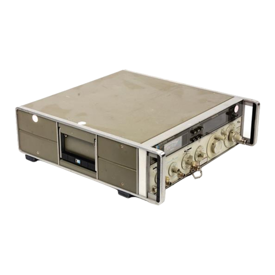
artisan 8640B Technical Manual (411 pages)
SIGNAL GENERATOR
Brand:
artisan
| Category:
Portable Generator
| Size: 8 MB
Table of Contents
Table of Contents
5
Administrative Storage
19
Destruction of Army Material to Prevent Enemy Use
19
General
19
Maintenance Forms and Records
19
Reporting Equipment Improvement Recommendations (EIR)
19
HP Model 8640B Signal Generator (Option 001) and Accessories Supplied
20
Instrument Covered by Manual
21
Introduction
21
Section I
21
General Information
21
General Description
22
Measured Single Sideband Noise Vs Offset from Carrier
22
Performance Characteristics
22
Spectral Purity
22
Frequency Counter
23
Phase-Lock Mode
23
Specified Signal-To-Phase Noise Ratio
23
Amplitude Modulation
24
Frequency Modulation
24
Pulse Modulation
24
Pulsed RF
24
FM Distortion Vs FM Rate
25
Multi-Function Meter and Annunciators
25
Output Level
25
Standard and Optional Audio Oscillators
25
Accessories Supplied
26
Equipment Available
26
Options
26
Test Equipment Required
27
Warranty
27
Recommended Test Equipment
33
Recommended Test Accessories
40
FM Linearity Circuit
41
Installation
43
Initial Inspection
43
Introduction
43
Line Selector
43
Power Requirements
43
Preparation for Use
43
Line Voltage Selection
44
Power Cable
44
Power Cables Available
44
Bench Operation
45
Environment
45
Mating Connectors
45
Operating Environment
45
Packaging
45
Rack Mounting
45
Storage and Shipment
45
Preparation for Rack Mounting
46
Operation
47
Introduction
47
Lamp Replacement
47
Operating Instructions
47
Operator's Checks
47
Operator's Maintenance
47
Panel Features
47
Front Panel Controls, Indicators, and Connectors
48
Rear Panel Controls, and Connectors
52
Operator's Checks
57
Setting the Frequency and Amplitude Controls
58
Setting the Modulation Controls
61
Performance Tests
65
Equipment Required
65
Introduction
65
Test Procedures
65
Test Record
65
Frequency Range Test
66
Frequency Accuracy and Fine Tune Test
67
Frequency Stability Vs Time and Restabilization Time Test
69
Frequency Stability Vs Time and Restabilization Time
70
Frequency Stability Vs Temperature Test
71
Frequency Stability Vs Line Voltage Test
72
Frequency Stability Vs Load, Level, and Mode Test
73
Frequency Stability Vs Load, Level, and Mode Test
74
Harmonics Test
75
Specifications
75
Sub-Harmonics and Non-Harmonic Spurious Test
77
520 Mhz Notch Filter
78
Single Sideband Phase Noise Test
79
Single Sideband Phase Noise Test Setup
79
Single Sideband Broadband Noise Floor Test
81
Single Sideband Broadband Noise Floor Test Setup
82
Residual am Test
84
Residual am Test Setup
84
Residual FM Test
85
Test Setup
87
Output Level Accuracy Test (Abbreviated)
88
Output Level Accuracy Test Setup (Abbreviated)
89
Output Level Accuracy Test Setup (Complete)
95
Output Level Flatness Test
100
Output Level Flatness Test Setup
100
Output Impedance Test (in Band)
101
Output Level Flatness Test
101
Output Impedance Test Setup (in Band)
102
Output Impedance Test (out of Band)
103
Output Impedance Test Setup (out of Band)
104
Auxiliary Output Test
105
Output Leakage Test
106
Output Leakage Test Setup
106
Internal Modulation Oscillator Test
108
Internal Modulation Oscillator Test Setup
108
Internal Modulation Oscillator Distortion Test (Option 001)
109
Internal Modulation Oscillator Distortion Test Setup
110
AM 3 Db Bandwidth Test
111
AM 3 Db Bandwidth Test Setup
111
AM Distortion Test
113
AM Distortion Test Setup
113
AM Sensitivity and Accuracy Test
114
AM Sensitivity and Accuracy Test Setup
115
Peak Incidental Phase Modulation Test Setup
118
Peak Incidental Phase Modulation Test
119
Pulse Modulation Test
120
Pulse Modulation Test Setup
121
Pulse Measurements
122
FM 3 Db Bandwidth Test Setup
125
FM Distortion Test Setup
127
FM Sensitivity and Accuracy Test Setup
129
Incidental am Test Setup
132
Counter External Sensitivity Test Setup
134
Internal Reference Accuracy Test Setup
135
Internal Reference Drift Rate (Stability) Test Setup
137
Performance Test Record
141
Pulse On/Off Ratio Test
146
Counter External Sensitivity Test
147
FM 3 Db Bandwidth Test
147
FM Distortion Test
147
FM Sensitivity and Accuracy Test
147
Incidental am Test
147
Internal Reference Accuracy Test
147
Internal Reference Drift Rate (Stability) Test
148
Phase Lock Restabilization Time Test
148
Recommended Test Abridgements
149
Blade Tuning Tools
152
Introduction
152
Pozidriv Screwdrivers
152
Safety Considerations
152
Service Aids
152
Test Equipment Required
152
Factory Selected Components
153
Post-Repair Test and Adjustments
154
Post-Repair Test and Adjustments
155
Fixed-Frequency Modulation Oscillator Adjustment
159
Power Supply Adjustments
159
Variable-Frequency Modulation Oscillator Adjustment (Option 001)
160
Meter Adjustments
163
RF Detector Offset Adjustment
163
Output Level Knob Adjustment
164
Output Level Vernier and Meter Adjustment
165
Output Level Vernier and Meter Adjustment Test Setup
166
AM Sensitivity Adjustment
168
AM Sensitivity Adjustment Test Setup
168
Peak Deviation and Range Switch Adjustment
170
Range Switch Adjustment
171
VT Pot (A3R1) Adjustment
172
VT Pot Adjustment
172
VT Voltage Adjustment
173
Filter Terminology
174
RF Filter Adjustment
174
RF Filter Adjustment Test Setup
175
RF Filter Check
177
Mhz High Band Capacitor Adjustment Orientation
178
Preliminary FM Adjustments
178
FM Linearity Adjustment
180
FM Linearity Display
183
FM Sensitivity Adjustment
183
FM Sensitivity Adjustment Test Setup
184
Internal Reference Frequency Adjustment
185
Internal Reference Frequency Adjustment Test Setup
186
RF Oscillator End Stop Adjustment
187
In Maximum Ccw Position. Top View with Instrument Upside down
188
RF Oscillator Output Power Adjustment
189
RF Oscillator Output Power Adjustment Test Setup
189
FM Linearity Adjustment (Alternate)
190
FM Linearity Adjustment (Alternate) Test Setup
191
Replaceable Parts
193
Abbreviations
193
Exchange Assemblies
193
Introduction
193
Ordering Information
193
Replaceable Parts List
193
Spare Parts Kit
193
Illustrated Parts Breakdowns
194
Part Numbers for Exchange Assemblies
194
Illustrated Parts Breakdown
194
Reference Designations and Abbreviations
195
Replaceable Parts
197
A26A4)
228
Cabinet Parts
232
Type N Connector
233
Code List of Manufacturers
234
Manual Changes
235
Introduction
235
Manual Changes by Serial Number
235
Summary of Changes by Component
236
Manual Change Instructions
244
A8A2 Counter/Lock Board Assembly Backdating (Change B)
246
A3A4 Connector Board Assembly Backdating (Change C)
247
A26A1 Power Amplifier and AGC Detector Assembly Backdating (Change D)
248
A26A2U1 Backdating (Change E)
251
A8A1 RF Scaler Assembly Backdating (Change E)
252
A12 Rectifier Assembly Backdating (Change F)
253
A8A1 RF Scaler Assembly Component Locations
265
A22 +20V and -20V Regulator Assembly Component Locations
267
A26A1 Power Amplifier and AGC Detector Assembly Component Locations
273
A4 Meter/Annunciator Drive Assembly
278
P/O A8A2 Counter/Lock Board Assembly Component
281
A12 Rectifier Assembly Component Locations
282
P/O A3A4 Connector Board Assembly Component Location
283
P/O A8A2 Counter/Lock Board Assembly Component Locations
287
Component Locations
294
Component Locations
295
FM Amplifiers Schematic Diagram
296
FM Shaping Circuits and Phase Lock Loop Filter Schematic Diagram
298
Component Locations
299
Over-Deviation Detector and Meter Control Circuits Schematic Diagram
301
A8A2 Counter/Lock Board Assembly Improvements (Serial Prefix 1229A)
312
Elimination of Frequency Shift in Expand X100 Mode (Serial Prefix 1229A)
312
Improved FM Metering Accuracy (Serial Prefix 1229A)
312
Instrument Improvement Modifications
312
A8A4 Counter Display Assembly Modification
313
A26A1 Power Amplifier and AGC Detector Assembly Improvement (Serial Prefix 1229A)
314
Fixed-Frequency Modulation Oscillator (All, A13)
314
Improved Audio Output Level Accuracy (Serial Prefix 1229A)
314
Reduction of RFI Leakage from Front Panel (Serial Prefix 1244A and Below)
314
A26A4 AGC Amplifier Assembly Improvement (Serial Prefix 1245A and Below)
315
Reduction of RFI Leakage from RF Oscillator (Serial Prefix 1246A and Below)
315
Replacement A7 FM Shaping Assembly (Serial Prefix 1246A and Below)
315
Replacement A9 Peak Deviation and Range Switch Assembly (Serial Prefix 1246A and Below)
315
Prefix 1249A)
317
A5 FM Amplifier Assembly Improvement (Serial Prefix 125La and Below)
317
A8A2 Counter/Lock Board Assembly Improvement
317
(Serial Prefix 1251A and Below)
317
Front Panel Meter M1 Replacement (Serial Prefix 125La and Below)
317
A26 AM/AGC and RF Amplifier Assembly Improvement
318
A26A4 AGC Amplifier Assembly Improvement
318
A10A2 RF Divider Assembly Improvement (Serial Prefix 1313A and Below)
319
A10A2 RF Divider Assembly Improvement (Serial Number Prefixes 1333A and Below)
320
A10A2 RF Divider Assembly Improvement (Serial Numbers 1316A00464 and Below)
320
A8A4 Counter Display Assembly Improvement
320
Improved Audio Output Level Flatness (Serial Prefixes 1244A through 1316A)
320
Improved FM Bandwidth on 5Khz Deviation Range
320
Improved Noise Performance (Serial Prefixes 1327A and Below)
320
Power Supply Improvement (Serial Prefix 1313A and Below)
320
A18, A20, and A22 Power Supply Regulator
321
Time Base Vernier and Pot Replacement (Serial Prefix 1333A and Below)
321
All Variable Frequency Modulation Oscillator (Option 001) Improvement (Serial Number Prefixes 1350A and Below)
322
Improvement in Lock Acquisition Capability (Serial Number Prefixes 1350A and Below)
322
Line Switch Modification (Serial Number Prefixes 1406A and Below)
322
Regulator Improvement (Serial Number Prefixes 1405A and Below)
322
Reliability Improvements in am and Pulse Circuits (Serial Number Prefixes 1345A and Below)
322
REDUCE PEAK POWER" Lamp Drive Modification (Serial Number Prefix 1526A and Below)
323
Service
325
Reduction in Popcorn Noise on Power Supplies (Serial Number Prefixes 1406A and Below)
323
Operation (Serial Number Prefixes 1423A and Below)
323
Introduction
325
Principles of Operation
325
Recommended Test Equipment
325
Schematic Diagram Notes
325
Service Aids
325
Troubleshooting
325
Signal Generator with Circuit Boards on Extenders
326
Component Replacement
327
Etched Circuits
327
Etched Conductor Repair
327
Factory Selected Components
327
Repair
327
Etched Circuit Soldering Equipment
328
Examples of Diode and Transistor Marking Methods
328
Basic Circuit Theory
329
Binary Circuits and Symbols
329
Illustrated Parts Breakdowns
329
Binary Symbols
330
Logic Levels
330
D Flip-Flop
331
Schmitt Trigger
331
Triggered Flip-Flop
331
Binary Latch
332
Binary Registers
332
Binary Shift Register
332
Multiple Input J/K Flip-Flop
332
Binary Latch
333
Binary Shift Register
333
Decade Counters and Symbols
333
Programmable Counter
334
Linear Integrated Circuits
335
Programmable Up/Down Counter
336
Operational Amplifier
337
Assembly Information Index
338
Comparator
338
Service Sheets
338
Schematic Diagram
339
Overall Block Diagram
343
Overall Block Diagram
344
FM Circuits and RF Oscillator Block Diagram
345
FM Circuits and RF Oscillator Troubleshooting
346
AM/AGC Circuits and Output Amplifier Block Diagram
347
AM/AGC Circuits and Output Amplifier Troubleshooting
348
Counter/Lock Circuits Block Diagram
349
Counter/Lock Circuits Troubleshooting
350
RF Oscillator Simplified Diagram
351
P/O A3A4 Connector Board Assembly Component Locations
352
P/O A9 Peak Deviation and Range Switch Assembly
352
Component Locations
352
A5 FM Amplifier Assembly Component Locations
353
P/O A9 Peak Deviation and Range Switch Assembly Component Locations
353
P/O A7 FM Shaping Assembly Component Locations
357
A11 Variable-Frequency Modulation Oscillator
361
Variable-Frequency Modulation Oscillator (Option 001) Schematic Diagram
361
A10A1 RF Filter Assembly Component Locations
362
Variable-Frequency Modulation Oscillator for Option
362
RF Filters (A10Al)
362
RF Dividers (A10A2)
364
AM Preamplifier (A13, A26A2)
370
RF Amplifier, Pulse Switching, and Step Attenuator (A1, A26A1, A26A2)
370
AM Interconnections and RF ON/OFF Switch Schematic Diagram
373
AM Interconnections and RF ON/OFF Switch (A9, A26)
374
RF Vernier Schematic Diagram
375
A2 Meter Switch/Detector Assembly Component Location
376
Meter Drive Amplifier Data
376
RF Vernier (A1A1, A26)
376
Meter Circuits Schematic Diagram
377
P/O A6 Annunciator Assembly Component Locations
377
Meter Circuits (A2, A4, A6)
378
Counter RF Scaler Schematic Diagram
379
P/O A8A3 Time Base Assembly Component Locations
379
Count Modes of Counter A8A3U15
380
Count Modes of Counters A8A3U13 and U14
380
Counter RF Scaler (A8A1, A8A3)
380
Data Inputs of Decimal Point Shift Register
380
Total Count of Time Base Reference Counters U13, U14, and U15
380
Counter Time Base Schematic Diagram
381
P/O A8A3 Time Base Assembly Component Locations
381
Counter Time Base (A8A3, A9)
382
A8A4 Counter Display Assembly Component Locations (P/O A8)
383
Up/Down Counter and Display Schematic Diagram
383
Counter Phase Lock Circuits (A8A2)
384
Up/Down Counter and Display (A8A2, A8A4)
384
Counter Phase Lock Circuits Schematic Diagram
385
Current Foldback
386
Power Supply Circuits Schematic Diagram
387
Power Supply Circuits (A12, A14, A20, A22)
388
Regulator and Fan Circuits (A16, A18)
390
A17 Power Supply Mother Board Assembly Component Locations
391
Power Supply Mother Board Schematic Diagram
391
A13 Modulation/Metering Mother Board Assembly Component Locations
392
Power Supply Mother Board (A17)
392
Modulation/Metering Mother Board (A13)
394
A1 Output Level Assembly Illustrated Parts Breakdown
395
Al Assembly Removal and Disassembly
396
A8 Assembly Removal and Disassembly
396
A9 Peak Deviation and Range Switch Assembly Illustrated Parts Breakdown
399
A9 and All Assemblies Removal and Disassembly
400
A10 Assembly Removal and Disassembly
400
A10 Divider/Filter Assembly Illustrated Parts Breakdown
401
A26 AM/AGC and RF Amplifier Illustrated Parts Breakdown
403
Bottom Internal Views (Option 001 Shown)
406
Advertisement
Advertisement
Related Products
artisan 880
artisan 8144-20
artisan 8145-20
artisan 8145-30
artisan 8144-30
artisan PEFT Junior
artisan Categories
Sewing Machine
Controller
Measuring Instruments
Computer Hardware
Control Unit
More artisan Manuals
Login
Sign In
OR
Sign in with Facebook
Sign in with Google
Upload manual
Upload from disk
Upload from URL