
Subscribe to Our Youtube Channel
Related Manuals for artisan 8640B

Summary of Contents for artisan 8640B
- Page 1 (217) 352-9330 | Click HERE Find the Keysight / Agilent 8640B at our website:...
- Page 2 DIRECT SUPPORT, AND GENERAL SUPPORT MAI'NTENANCE MANUAL (INCLUDING REPAIR PARTS) 8640B SIGNAL GENERATOR (INCLUDING OPTION 001) (PATRIOT AIR DEFENSE GUIDED MISSILE SYSTEM) HEADQUARTERS, DEPARTMENT OF THE ARMY SEPTEMBER 1986 Artisan Technology Group - Quality Instrumentation ... Guaranteed | (888) 88-SOURCE | www.artisantg.com...
- Page 3 Read FM 21-11, First Aid for Soldiers, and learn how to administer artificial respiration. WARNING Do not be misled by the term "low voltage." Under adverse conditions, potentials as low as 50 volts may cause death. a/(b blank) Artisan Technology Group - Quality Instrumentation ... Guaranteed | (888) 88-SOURCE | www.artisantg.com...
- Page 4 Publications and Blank Forms), or DA Form 2028-2 direct to: Commander, U.S. Army Missile Command, ATTN: AMSMILC-ME-PM, Redstone Arsenal, Alabama 35898-5238. A reply will be furnished to you. Artisan Technology Group - Quality Instrumentation ... Guaranteed | (888) 88-SOURCE | www.artisantg.com...
-
Page 5: Table Of Contents
Line Voltage Selection .............. 2-11 Power Cable ................2-13 Mating Connectors ..............2-15 Operating Environment ............. 2-18 Bench Operation ............... 2-20 Rack Mounting ................. 2-22 Storage and Shipment ..............Artisan Technology Group - Quality Instrumentation ... Guaranteed | (888) 88-SOURCE | www.artisantg.com... - Page 6 Output Leakage Test..............4-42 4-30 Internal Modulation Oscillator Test ..........4-44 4-31 Internal Modulation Oscillator Distortion Test (Option 001) ..............4-45 4-32 AM 3 dB Bandwidth Test ..............4-47 Artisan Technology Group - Quality Instrumentation ... Guaranteed | (888) 88-SOURCE | www.artisantg.com...
- Page 7 VT Pot (A3R1) Adjustment ............5-21 5-36 VT Voltage Adjustment ..............5-22 5-37 RF Filter Adjustment ..............5-23 5-38 Preliminary FM Adjustments ............5-27 5-39 FM Linearity Adjustment ..............5-29 Artisan Technology Group - Quality Instrumentation ... Guaranteed | (888) 88-SOURCE | www.artisantg.com...
- Page 8 Replacement A7 FM Shaping Assembly (Serial Prefix 1246A and Below) ............7-81 7-31 Replacement A9 Peak Deviation and Range Switch Assembly (Serial Prefix 1246A and Below) ................. 7-81 Artisan Technology Group - Quality Instrumentation ... Guaranteed | (888) 88-SOURCE | www.artisantg.com...
- Page 9 A12 Rectifier Assembly Input Crowbar Failures (Serial Number Prefixes 1330A and Below) ......7-87 7-75 Reliability Improvements in AM and Pulse Circuits (Serial Number Prefixes 1345A and Below) ................7-88 Artisan Technology Group - Quality Instrumentation ... Guaranteed | (888) 88-SOURCE | www.artisantg.com...
- Page 10 Binary Circuits and Symbols ............. 8-52 Binary Registers ............... 8-53 Binary Latch ................8-57 Binary Shift Register ..............8-61 Decade Counters and Symbols ..........8-69 Linear Integrated Circuits ............8-11 Artisan Technology Group - Quality Instrumentation ... Guaranteed | (888) 88-SOURCE | www.artisantg.com...
- Page 11 FM Distortion vs FM Rate .............. 520 MHz Notch Filter ..............1-21 FM Linearity Circuit ............... 1-22 Line Selector ................. Power Cables Available ..............Preparation for Rack Mounting ............viii Artisan Technology Group - Quality Instrumentation ... Guaranteed | (888) 88-SOURCE | www.artisantg.com...
- Page 12 Output Level Vernier and Meter Adjustment Test Setup ....5-15 AM Sensitivity Adjustment Test Setup ........... 5-17 VT Pot Adjustment ................ 5-21 Filter Terminology ................5-23 RF Filter Adjustment Test Setup ........... 5-24 Artisan Technology Group - Quality Instrumentation ... Guaranteed | (888) 88-SOURCE | www.artisantg.com...
- Page 13 Basic Decade Counter (Scaler) ............. 8-12 Programmable Counter ..............8-10 8-13 Programmable Up/Down Counter ..........8-12 8-14 Operational Amplifier ..............8-13 8-15 Comparator ................... 8-14 8-16 Overall Block Diagram ..............8-19 Artisan Technology Group - Quality Instrumentation ... Guaranteed | (888) 88-SOURCE | www.artisantg.com...
- Page 14 Component Locations ..............8-45 8-44 P/O A26A2 AM Offset and Pulse Switching Assembly Component Locations ..............8-45 8-45 RF Amplifier, Pulse Switching, and Step Attenuator Schematic Diagram ............... 8-45 Artisan Technology Group - Quality Instrumentation ... Guaranteed | (888) 88-SOURCE | www.artisantg.com...
- Page 15 A17 Power Supply Mother Board Assembly Component Locations................... 8-67 8-73 Power Supply Mother Board Schematic Diagram ......8-67 8-74 A13 Modulation/Metering Mother Board Assembly Component Locations ............... 8-68 Artisan Technology Group - Quality Instrumentation ... Guaranteed | (888) 88-SOURCE | www.artisantg.com...
- Page 16 (A1, A26A1, A26A2) ..............8-44 AM Preamplifier (A13, A26A2) ............8-46 AM Interconnections and RF ON/OFF Switch (A9, A26) ....8-48 RF Vernier (A1A1, A26) ..............8-50 xiii Artisan Technology Group - Quality Instrumentation ... Guaranteed | (888) 88-SOURCE | www.artisantg.com...
- Page 17 A10 Assembly Removal and Disassembly ........8-76 A26 Assembly Removal and Disassembly ........8-78 General Removal Procedures and Top Internal Views....8-80 Rear Panel and Bottom Internal Views .......... 8-83 Artisan Technology Group - Quality Instrumentation ... Guaranteed | (888) 88-SOURCE | www.artisantg.com...
- Page 18 (normal blow time delay, etc.) are used for replacement. The use of repaired fuses and the short-circuiting of fuseholders must be avoided. xv/(xvi blank) Artisan Technology Group - Quality Instrumentation ... Guaranteed | (888) 88-SOURCE | www.artisantg.com...
-
Page 19: General
0-4 DESTRUCTION OF ARMY MATERIAL TO PREVENT ENEMY USE For procedures for destruction of Army material to prevent enemy use, see section XI of TM 9-4935-393-14-1. 0-1/(0-2 blank) Artisan Technology Group - Quality Instrumentation ... Guaranteed | (888) 88-SOURCE | www.artisantg.com... -
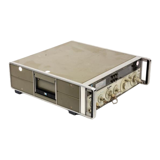
Page 20: Hp Model 8640B Signal Generator (Option 001) And Accessories Supplied
Model 5640B TM 9-4935-601-14-7&P Figure 1-1. HP Model 8640B Signal Generator (Option 001) and Accessories Supplied Artisan Technology Group - Quality Instrumentation ... Guaranteed | (888) 88-SOURCE | www.artisantg.com... -
Page 21: Section I
This supplement to this should stay with the instrument for use by the operator. Additional copies can be ordered through your nearest Artisan Technology Group - Quality Instrumentation ... Guaranteed | (888) 88-SOURCE | www.artisantg.com... -
Page 22: General Description
Figure 1-2 shows the typical measured single-sideband sub-harmonic and non harmonic-spurious are virtually noise performance in a eliminated. A band over-range of 7% to 10% is also Artisan Technology Group - Quality Instrumentation ... Guaranteed | (888) 88-SOURCE | www.artisantg.com... -
Page 23: Frequency Counter
X100 EXPAND buttons near the display. In the X100 EXPAND mode or when counting external inputs. Maximum resolution in the locked mode is I kHz at 500 MHz, increasing to 1 Hz at 500 kllz. Artisan Technology Group - Quality Instrumentation ... Guaranteed | (888) 88-SOURCE | www.artisantg.com... -
Page 24: Amplitude Modulation
IF filters and discriminators. Figure 1-4. AM distortion us AM rate measured at 200 MHz and +13 dBm, but applies to all bands. (Supplemental information only.) Artisan Technology Group - Quality Instrumentation ... Guaranteed | (888) 88-SOURCE | www.artisantg.com... -
Page 25: Standard And Optional Audio Oscillators
3 V to 20 mV into 600Q. This audio oscillator, directly on the attenuator dial or (for greater accuracy) Option 001, extends the usable CW range of the autoranging meter. meter generator down to 20 Hz. Artisan Technology Group - Quality Instrumentation ... Guaranteed | (888) 88-SOURCE | www.artisantg.com... -
Page 26: Options
1-63. The Model 8640B is supplied with the following accessories (they are shown in Figure 1-1) Line Power Cable (HP 8120-1378) 2 Amp Fuse (HP 2110-0002) 1 Amp Fuse (HP 2110-0001) Artisan Technology Group - Quality Instrumentation ... Guaranteed | (888) 88-SOURCE | www.artisantg.com... -
Page 27: Warranty
IEC Publication 348 Safety Requirements for Electronic Measuring Apparatus. The instruction manual contains information, warnings, and cautions which must be followed by the user to ensure safe operation and to retain the instrument in safe condition. Artisan Technology Group - Quality Instrumentation ... Guaranteed | (888) 88-SOURCE | www.artisantg.com... - Page 28 (CW to FM) <200 Hz which- ever is greater In the External Doubler Band. the 8640B counter displays the actual doubled output frequency. and the FM meter indicates the proper peak deviation. When phase locked, Counter Resolution error is eliminated.
- Page 29 10 dB of vernier range.) into 50Ω. These specifications are given for the 8640B internal reference. When using an external reference, drift in the locked mode will depend on the external reference characteristics. Artisan Technology Group - Quality Instrumentation ... Guaranteed | (888) 88-SOURCE | www.artisantg.com...
- Page 30 50 kHz AM is possible above +13 dBm as long as the combination of the AM depth plus carrier output level does not exceed +19 dBm. 1-10 Artisan Technology Group - Quality Instrumentation ... Guaranteed | (888) 88-SOURCE | www.artisantg.com...
- Page 31 512- 1024 5120 position. Maximum peak deviation position, ±9% typically. With 86408 in, LOCKED MODE, external FM is possible only for rates greater than 50 Hz. 1-11 Artisan Technology Group - Quality Instrumentation ... Guaranteed | (888) 88-SOURCE | www.artisantg.com...
- Page 32 Weight: Net, 45 lb (20,4 kg). Dimensions are for general information only. If dimensions are required for building special enclosures, contact your HP office. 1-12 Artisan Technology Group - Quality Instrumentation ... Guaranteed | (888) 88-SOURCE | www.artisantg.com...
-
Page 33: Recommended Test Equipment
HP 355D Attenuator steps Option H36 Accuracy: ± (0.02 ± 0.015 dB/10 dB step) at 3 MHz *P = Performance; A = Adjustment; T = Troubleshooting 1-13 Artisan Technology Group - Quality Instrumentation ... Guaranteed | (888) 88-SOURCE | www.artisantg.com... - Page 34 FM Discriminator Ranges: 100 kHz to 10 MHz HP 5210A Linear Analog Output: 1V for full scale *P = Performance; A = Adjustment: T = Troubleshooting 1-14 Artisan Technology Group - Quality Instrumentation ... Guaranteed | (888) 88-SOURCE | www.artisantg.com...
- Page 35 <1 x 10 /s rms short term stability <1 x 10 , 0 - 50° C temper- ature stability *P = Performance; A = Adjustments; T = Troubleshooting 1-15 Artisan Technology Group - Quality Instrumentation ... Guaranteed | (888) 88-SOURCE | www.artisantg.com...
- Page 36 Output: 1 MHz (level compatible HP 105B with Frequency Counter) Stability: <5 x 10 /24 hours <5 x 10 *P = Performance; A = Adjustments; T = Troubleshooting 1-16 Artisan Technology Group - Quality Instrumentation ... Guaranteed | (888) 88-SOURCE | www.artisantg.com...
- Page 37 Average Noise Level: <-120 dBm (50Ω) with 1 kHz IF bandwidth Spurious Responses: >60 dB down for nominal specified inputs *P = Performance; A = Adjustments; T = Troubleshooting 1-17 Artisan Technology Group - Quality Instrumentation ... Guaranteed | (888) 88-SOURCE | www.artisantg.com...
- Page 38 Range: 20 Hz to 600 kHz HP 652A P,A,T Output Impedance: 600Ω and 50Ω Distortion: >40 dB down Output Level: >1 Vrms *P = Performance; A = Adjustments; T = Troubleshooting 1-18 Artisan Technology Group - Quality Instrumentation ... Guaranteed | (888) 88-SOURCE | www.artisantg.com...
- Page 39 Voltage Ratio Accuracy: 0.2 dB VSWR Bridge Range: 0.45 - 550 MHz Wiltron Model Directivity: >40 dB 60N50 Connectors: Type N *P = Performance; A = Adjustments; T = Troubleshooting 1-19 Artisan Technology Group - Quality Instrumentation ... Guaranteed | (888) 88-SOURCE | www.artisantg.com...
-
Page 40: Recommended Test Accessories
0.001 µ F Capacitor HP 0160-0153 0.033 µ F Capacitor HP 0160-0163 HP 0757-0280 1 kΩ Resistor HP 0757-0442 10 kΩ Resistor SPST Switch HP 3101-0163 1-20 Artisan Technology Group - Quality Instrumentation ... Guaranteed | (888) 88-SOURCE | www.artisantg.com... -
Page 41: Fm Linearity Circuit
Model 8640B TM 9-4935-601-14-7&P Figure 1-7. 520/1040 MHz Notch Filter. Figure 1-8. FM Linearity Circuit. 1-21 Artisan Technology Group - Quality Instrumentation ... Guaranteed | (888) 88-SOURCE | www.artisantg.com... - Page 42 Model 8640B TM 9-4935-601-14-7&P Figure 1-9. Noise Phase Lock Circuit. 1-22 Artisan Technology Group - Quality Instrumentation ... Guaranteed | (888) 88-SOURCE | www.artisantg.com...
-
Page 43: Installation
1-1, and procedures for checking electrical performance phase. Power consumption is 175 VA maximum. are given in Section IV. If the contents are incomplete, Figure 2-1. Line Selector Artisan Technology Group - Quality Instrumentation ... Guaranteed | (888) 88-SOURCE | www.artisantg.com... -
Page 44: Line Voltage Selection
Refer to Figure 2-2 for the part numbers of the power cable plugs appears on the top-left side (see Figure 2-1). available. Figure 2-2. Power Cables Available. Artisan Technology Group - Quality Instrumentation ... Guaranteed | (888) 88-SOURCE | www.artisantg.com... -
Page 45: Mating Connectors
Artisan Technology Group - Quality Instrumentation ... Guaranteed | (888) 88-SOURCE | www.artisantg.com... -
Page 46: Preparation For Rack Mounting
Mark the shipping container FRAGILE to assure firm cushion and prevent movement inside the careful handling. Figure 2-3. Preparation for Rack Mounting. Artisan Technology Group - Quality Instrumentation ... Guaranteed | (888) 88-SOURCE | www.artisantg.com... -
Page 47: Operation
To service the fulter use a No. 2 Pozidriv screwdriver (HP 8710-0900) to remove the four screws that hold the filter to the rear panel. Then clean it, using Artisan Technology Group - Quality Instrumentation ... Guaranteed | (888) 88-SOURCE | www.artisantg.com... -
Page 48: Front Panel Controls, Indicators, And Connectors
MHz, depending upon setting of causing FM deviation to exceed limits. PEAK DEVIATION switch (e.g., with PEAK Figure 3-2. Front Panel Controls, Indicators, and Connectors (1 of 4). Artisan Technology Group - Quality Instrumentation ... Guaranteed | (888) 88-SOURCE | www.artisantg.com... - Page 49 When control is not in CAL position, the UNCAL lamp lights to indicate that the counter is uncalibrated. Figure 3-2. Front Panel Controls, Indicators, and Connectors (2 of 4) Artisan Technology Group - Quality Instrumentation ... Guaranteed | (888) 88-SOURCE | www.artisantg.com...
- Page 50 (never more than 5 Vpk). Output for internal oscillator whenever FM selector is set to Figure 3-2. Front Panel Controls, Indicators, and Connectors (3 of 4) Artisan Technology Group - Quality Instrumentation ... Guaranteed | (888) 88-SOURCE | www.artisantg.com...
- Page 51 OFF: no AM. INT: AM by internal oscillator. Figure 3-2. Front Panel Controls, Indicators, and Connectors (4 of 4) Artisan Technology Group - Quality Instrumentation ... Guaranteed | (888) 88-SOURCE | www.artisantg.com...
-
Page 52: Rear Panel Controls, And Connectors
(such as another Model 8640B) by using the TIME BASE Reference jack and switch. Figure 3-3. Rear Panel Controls and Connectors Artisan Technology Group - Quality Instrumentation ... Guaranteed | (888) 88-SOURCE | www.artisantg.com... - Page 53 12 FREQUENCY TUNE ........Centered (Four turns from stop) 11 FINE TUNE ................Centered 10 OUTPUT LEVEL ..............100 mVOLTS 8 RF ON/OFF ..................ON Figure 3-4. Operator's Checks (1 of 5) Artisan Technology Group - Quality Instrumentation ... Guaranteed | (888) 88-SOURCE | www.artisantg.com...
- Page 54 Set COUNTER MODE EXPAND 5 to OFF (buttons out). With RANGE 13 set as follows, FREQUENCY 6 should read approximately as shown: Figure 3-4. Operator's Checks (2 of 5) Artisan Technology Group - Quality Instrumentation ... Guaranteed | (888) 88-SOURCE | www.artisantg.com...
- Page 55 Set OUTPUT LEVEL 10 to 500 mVOLTS; the meter 3 should indicate 5 on the 0-10 SCALE (the 0-10 SCALE annunciator 2 should be lit). Figure 3-4. Operator's Checks (3 of 5) Artisan Technology Group - Quality Instrumentation ... Guaranteed | (888) 88-SOURCE | www.artisantg.com...
- Page 56 PEAK DEVIATION 16 is set to 5 kHz and the vernier is full counterclockwise; the meter 3 should indicate 0. Figure 3-4. Operator's Checks (4 of 5) 3-10 Artisan Technology Group - Quality Instrumentation ... Guaranteed | (888) 88-SOURCE | www.artisantg.com...
-
Page 57: Operator's Checks
FREQUENCY (18), in turn, to 400 Hz and 1 kHz; the FREQUENCY readout (6) should display approximately ".000400" and ".001000" MHz. Figure 3-4. Operator's Checks (5 of 5) 3-11 Artisan Technology Group - Quality Instrumentation ... Guaranteed | (888) 88-SOURCE | www.artisantg.com... -
Page 58: Setting The Frequency And Amplitude Controls
On some frequency bands it will be necessary to use the COUNTER MODE EXPAND controls to tune between adjacent counts. Figure 3-5. Setting the Frequency and Amplitude Controls (1 of 3) 3-12 Artisan Technology Group - Quality Instrumentation ... Guaranteed | (888) 88-SOURCE | www.artisantg.com... - Page 59 RF ON/OFF function may be easily modified (see Service Sheet 5 in Section VIII). Figure 3-5. Setting the Frequency and Amplitude Controls (2 of 3) 3-13 Artisan Technology Group - Quality Instrumentation ... Guaranteed | (888) 88-SOURCE | www.artisantg.com...
- Page 60 OUTPUT LEVEL (10) voltage scale will be correct if the instrument is used with 75 ohm terminations. However, 1.76 dB must be subtracted from the dB scale for correct readings. Figure 3-5. Setting the Frequency and Amplitude Controls (3 of 3) 3-14 Artisan Technology Group - Quality Instrumentation ... Guaranteed | (888) 88-SOURCE | www.artisantg.com...
-
Page 61: Setting The Modulation Controls
With AM (23) set to INT, the internal modulation oscillator signal is present at the AM OUTPUT jack (19) (600 ohm source impedance). Its level is set by AUDIO OUTPUT LEVEL (21) Figure 3-6. Setting the Modulation Controls (1 of 4) 3-15 Artisan Technology Group - Quality Instrumentation ... Guaranteed | (888) 88-SOURCE | www.artisantg.com... - Page 62 (19) (50 ohm load impedance). The Signal Generator requires a positive level to produce an RF output. c. Set the desired pulse-on level using the OUTPUT LEVEL controls (10). Figure 3-6. Setting the Modulation Controls (2 of 4) 3-16 Artisan Technology Group - Quality Instrumentation ... Guaranteed | (888) 88-SOURCE | www.artisantg.com...
- Page 63 Vrms) signal applied to FM INPUT will now produce the desired peak deviation. (Do not use FM CAL when phase locked.) Figure 3-6. Setting the Modulation Controls (3 of 4) 3-17 Artisan Technology Group - Quality Instrumentation ... Guaranteed | (888) 88-SOURCE | www.artisantg.com...
- Page 64 OUTPUT (19) and FM OUTPUT (17) when the oscillator is providing both modulating signals. The outputs are in parallel and the parallel load should be greater than 600 ohms. Figure 3-6. Setting the Modulation Controls (4 of 4) 3-18 Artisan Technology Group - Quality Instrumentation ... Guaranteed | (888) 88-SOURCE | www.artisantg.com...
-
Page 65: Performance Tests
Incidental AM Test, sometimes known as AM on FM, has been omitted as being of secondary importance. Should your application require characterization of this specification, the test should be performed.) Artisan Technology Group - Quality Instrumentation ... Guaranteed | (888) 88-SOURCE | www.artisantg.com... -
Page 66: Frequency Range Test
FREQUENCY TUNE ......................... Full clockwise FINE TUNE ............................Centered RF ON/OFF..............................ON Set FREQUENCY TUNE full clockwise. The frequency counter should read 550 MHz or greater. 550.0 MHz _______________________ Artisan Technology Group - Quality Instrumentation ... Guaranteed | (888) 88-SOURCE | www.artisantg.com... -
Page 67: Frequency Accuracy And Fine Tune Test
35° C). When phase locked, Counter Resolution error is eliminated. Fine Tuning: Unlocked, >200 ppm total range. Locked mode, >±20 ppm by varying internal time base vernier. Artisan Technology Group - Quality Instrumentation ... Guaranteed | (888) 88-SOURCE | www.artisantg.com... - Page 68 Turn TIME BASE VERN fully ccw. The frequency counter should now read >1 kHz (>20 ppm) lower than the reading first noted in step 5. 1 kHz ___________________________ Artisan Technology Group - Quality Instrumentation ... Guaranteed | (888) 88-SOURCE | www.artisantg.com...
-
Page 69: Frequency Stability Vs Time And Restabilization Time Test
NOTE For these tests, ambient room temperature and line voltage must not change. Figure 4-1. Frequency Stability us Time and Restabilization Time Test Setup Artisan Technology Group - Quality Instrumentation ... Guaranteed | (888) 88-SOURCE | www.artisantg.com... -
Page 70: Frequency Stability Vs Time And Restabilization Time
Set RANGE to 32 - 64 MHz and set RF ON/OFF to OFF. After one minute set RF ON/OFF to ON. Wait 10 minutes and record the frequency for 10 minutes. The frequency change for the second 10 minutes should be <500 Hz. __________________________ 500 Hz Artisan Technology Group - Quality Instrumentation ... Guaranteed | (888) 88-SOURCE | www.artisantg.com... -
Page 71: Frequency Stability Vs Temperature Test
RANGE ............................32-64 MHz FREQUENCY TUNE ........................... 50 MHz RF ON/OFF..............................ON Set temperature controlled chamber for 150C. Allow Signal Generator to stabilize for two hours. Then note frequency counter reading. Artisan Technology Group - Quality Instrumentation ... Guaranteed | (888) 88-SOURCE | www.artisantg.com... -
Page 72: Frequency Stability Vs Line Voltage Test
A frequency counter is used to measure frequency shift as line voltage is changed +5% to -10%. Figure 4-3. Frequency Stability us Line Voltage Test Setup EQUIPMENT: Frequency Counter ....................HP 5327C Variable Voltage Transformer ................GR W5MT3A Artisan Technology Group - Quality Instrumentation ... Guaranteed | (888) 88-SOURCE | www.artisantg.com... -
Page 73: Frequency Stability Vs Load, Level, And Mode Test
RF OUTPUT LEVEL is changed 10 dB, and as modulation mode is changed from CW to FM. The frequency is monitored at the rear panel auxiliary RF output jack. Artisan Technology Group - Quality Instrumentation ... Guaranteed | (888) 88-SOURCE | www.artisantg.com... -
Page 74: Frequency Stability Vs Load, Level, And Mode Test
Set PEAK DEVIATION switch to 10 kHz and PEAK DEVIATION vernier full clockwise. Set FM to AC and again, note frequency counter reading. It should have changed less than 200 Hz. __________________________ 200 Hz 4-10 Artisan Technology Group - Quality Instrumentation ... Guaranteed | (888) 88-SOURCE | www.artisantg.com... -
Page 75: Harmonics Test
Connect generator's RF OUTPUT to analyzer's input after setting Signal Generator's controls as follows: Meter Function ............................. LEVEL COUNTER MODE: EXPAND ................... Off LOCK..................Off Source ..................INT 4-11 Artisan Technology Group - Quality Instrumentation ... Guaranteed | (888) 88-SOURCE | www.artisantg.com... - Page 76 Keeping the fundamental near the left edge of the display, tune FREQUENCY TUNE to the high end of the band. All harmonics should be as specified. 4-12 Artisan Technology Group - Quality Instrumentation ... Guaranteed | (888) 88-SOURCE | www.artisantg.com...
-
Page 77: Sub-Harmonics And Non-Harmonic Spurious Test
Residual AM and FM) >100 dB below carrier. DESCRIPTION: A notch filter is used to remove the fundamental. All non-harmonic spurious and sub-harmonics are then amplified and measured with a spectrum analyzer. 4-13 Artisan Technology Group - Quality Instrumentation ... Guaranteed | (888) 88-SOURCE | www.artisantg.com... -
Page 78: 520 Mhz Notch Filter
500 kHz. All non-harmonic spurious signals, and sub-harmonics should be below the -40 dB graticule on the display (> 100 dB down). 100 dB __________________________ 4-14 Artisan Technology Group - Quality Instrumentation ... Guaranteed | (888) 88-SOURCE | www.artisantg.com... -
Page 79: Single Sideband Phase Noise Test
SSB phase noise that is less than or equal to the specification for the test generator. Figure 4-6. Single Sideband Phase Noise Test Setup 4-15 Artisan Technology Group - Quality Instrumentation ... Guaranteed | (888) 88-SOURCE | www.artisantg.com... - Page 80 The DSB to SSB transfer is 6 dB because the mixing process translates two correlated 1 kHz BW portions of the noise into the 1 kHz BW of the analyzer-giving twice the effective noise voltage. 4-16 Artisan Technology Group - Quality Instrumentation ... Guaranteed | (888) 88-SOURCE | www.artisantg.com...
-
Page 81: Single Sideband Broadband Noise Floor Test
1 Hz bandwidth.) 0.5 to 512 MHz: >140 dB. * See Hewlett-Packard Application Note 150-4. Spectrum Analysis - Noise Measurements. 4-17 Artisan Technology Group - Quality Instrumentation ... Guaranteed | (888) 88-SOURCE | www.artisantg.com... -
Page 82: Single Sideband Broadband Noise Floor Test Setup
EXPAND ................... Off LOCK..................Off Source ..................INT AM................................OFF FM................................OFF RANGE ............................256-512 MHz FREQUENCY TUNE ........................500.000 MHz OUTPUT LEVEL....................... -7 dBm (Vernier max cw) RF ON/OFF..............................ON 4-18 Artisan Technology Group - Quality Instrumentation ... Guaranteed | (888) 88-SOURCE | www.artisantg.com... - Page 83 The noise level on the analyzer's display should decrease at least 10 dB. * See Hewlett-Packard Application Note 150-4. Spectrum Analysis - Noise Measurements. 4-19 Artisan Technology Group - Quality Instrumentation ... Guaranteed | (888) 88-SOURCE | www.artisantg.com...
-
Page 84: Residual Am Test
Connect equipment as shown in Figure 4-8 (with the generator connected to the rms voltmeter through the detector, amplifier, 15 kHz LPF, and across the 50 ohm load). Set Signal Generator's controls as follows: 4-20 Artisan Technology Group - Quality Instrumentation ... Guaranteed | (888) 88-SOURCE | www.artisantg.com... -
Page 85: Residual Fm Test
300 Hz 20 Hz Post-detection Noise 3 kHz 15 kHz 3 kHz 15 kHz Bandwidth 230 to 550 <5 Hz <15 Hz <15 Hz <30 Hz 4-21 Artisan Technology Group - Quality Instrumentation ... Guaranteed | (888) 88-SOURCE | www.artisantg.com... - Page 86 Reference Signal Generator ..................HP 8640A Mixer ........................HP 10514A 3 kHz Low-Pass Filter (LPF) ................ CIR-Q-TEL 5 Pole 15 kHz Low-Pass Filter (LPF) ..............CIR-Q-TEL 7 Pole 50 Ohm Load......................HP 11593A 4-22 Artisan Technology Group - Quality Instrumentation ... Guaranteed | (888) 88-SOURCE | www.artisantg.com...
-
Page 87: Test Setup
7. Set test Signal Generator's PEAK DEVIATION switch to 2.56 MHz. The average voltmeter reading should be less than 7.5 mVrms (i.e., <15 Hz (rms) residual FM). ------------------7.5 mVrms 4-23 Artisan Technology Group - Quality Instrumentation ... Guaranteed | (888) 88-SOURCE | www.artisantg.com... -
Page 88: Output Level Accuracy Test (Abbreviated)
OUTPUT LEVEL step attenuator, and the OUTPUT LEVEL vernier. If, in addition, level accuracy must be verified down to 145 dBm, see paragraph ,4-24. 4-24 Artisan Technology Group - Quality Instrumentation ... Guaranteed | (888) 88-SOURCE | www.artisantg.com... -
Page 89: Output Level Accuracy Test Setup (Abbreviated)
COUNTER MODE: EXPAND ................Off LOCK................Off Source ................INT AM ........................OFF FM ........................OFF RANGE..................256 - 512 MHz FREQUENCY TUNE................512 MHz OUTPUT LEVEL ..................+19 dBm RF ON/OFF ....................ON 4-25 Artisan Technology Group - Quality Instrumentation ... Guaranteed | (888) 88-SOURCE | www.artisantg.com... - Page 90 If, for example, the last power meter reading was -7.4 dBm, the vertical scale resolution is 2 dB/division, therefore, the signal peak should be 0.4 dB or 0.2 division below the center (reference) graticule line. 4-26 Artisan Technology Group - Quality Instrumentation ... Guaranteed | (888) 88-SOURCE | www.artisantg.com...
- Page 91 -2.5 - +2.5 8 steps ccw -57 dBm -2.5 - +2.5 9 steps ccw -7 dBm -2.5 - +2.5 10 steps ccw -77 dBm -2.5 - +2.5 4-27 Artisan Technology Group - Quality Instrumentation ... Guaranteed | (888) 88-SOURCE | www.artisantg.com...
- Page 92 The noise level on the analyzer's display should be >10 dB below the signal level. The signal should drop into the noise when the OUTPUT LEVEL vernier is turned fully ccw. 4-28 Artisan Technology Group - Quality Instrumentation ... Guaranteed | (888) 88-SOURCE | www.artisantg.com...
- Page 93 Spectrum Analyzer............HP 141T/8552B/8553B Tracking Generator ................HP 8443B Mixer (3 required) ................HP 10514A 4 MHz Low Pass Filter (2 required) ......... CIR-Q-TEL 3 Pole 4-29 Artisan Technology Group - Quality Instrumentation ... Guaranteed | (888) 88-SOURCE | www.artisantg.com...
- Page 94 An HP Model 432A Power Meter with a Model 478A Thermistor Mount can be used for this test. However, a 10 dB attenuator, such as the Model 8491A OPT 10, must be used with the mount. This will slightly degrade measurement accuracy. 4-30 Artisan Technology Group - Quality Instrumentation ... Guaranteed | (888) 88-SOURCE | www.artisantg.com...
-
Page 95: Output Level Accuracy Test Setup (Complete)
Model 8640B TM 9-4935-601-14-7&P PERFORMANCE TESTS 4-24. OUTPUT LEVEL ACCURACY TEST (Complete) (Cont'd) Figure 4-11. Output Level Accuracy Test Setup (Complete). 4-31 Artisan Technology Group - Quality Instrumentation ... Guaranteed | (888) 88-SOURCE | www.artisantg.com... - Page 96 -5 dBm -7.0 - -3.0 2 steps ccw +3 dBm +1.5 - +4.5 from full cw 3 steps ccw -7 dBm -8.5 - -5.5 from full cw 4-32 Artisan Technology Group - Quality Instrumentation ... Guaranteed | (888) 88-SOURCE | www.artisantg.com...
- Page 97 IF attenuator (the calibrated 10 dB step attenuator). The DVM should read -500 mVdc ±0.5 dB. If necessary, use test generator's OUTPUT LEVEL vernier to reset panel meter to +3 dB. 4-33 Artisan Technology Group - Quality Instrumentation ... Guaranteed | (888) 88-SOURCE | www.artisantg.com...
- Page 98 14. Set the IF attenuator to 0 dB, OUTPUT LEVEL to -97 dBm, and then adjust the OUTPUT LEVEL vernier so that the test generator's panel meter reads -97 dBm. The DVM should read -500 mVdc ± 1 dB. -445.6_____________-561.0 mVdc 4-34 Artisan Technology Group - Quality Instrumentation ... Guaranteed | (888) 88-SOURCE | www.artisantg.com...
- Page 99 19. Check output level accuracy at other output frequencies by setting the two generators for a 3 MHz difference frequency and repeating steps 1 through 18. 4-35 Artisan Technology Group - Quality Instrumentation ... Guaranteed | (888) 88-SOURCE | www.artisantg.com...
-
Page 100: Output Level Flatness Test
Source ................INT AM .......................OFF FM ........................OFF RANGE................... 32 - 64 MHz FREQUENCY TUNE................50 MHz OUTPUT LEVEL ............+13 dBm (Vernier max cw) RF ON/OFF ....................ON 4-36 Artisan Technology Group - Quality Instrumentation ... Guaranteed | (888) 88-SOURCE | www.artisantg.com... -
Page 101: Output Level Flatness Test
(i.e., the distance from the RF OUTPUT jack to the coaxial short is varied). VSWR is then calculated from the formula Vmax VSWR = Vmin 4-37 Artisan Technology Group - Quality Instrumentation ... Guaranteed | (888) 88-SOURCE | www.artisantg.com... -
Page 102: Output Impedance Test Setup (In Band)
AM ........................OFF FM ........................OFF RANGE..................256 - 512 MHz FREQUENCY TUNE................512 MHz OUTPUT LEVEL ............±10 dBm (Switch 1 step ccw from full cw) RF ON/OFF ....................ON 4-38 Artisan Technology Group - Quality Instrumentation ... Guaranteed | (888) 88-SOURCE | www.artisantg.com... -
Page 103: Output Impedance Test (Out Of Band)
The through port of the bridge is connected to a short circuit to establish a reference, then to the generator output. Return loss versus frequency is displayed on the spectrum analyzer. 4-39 Artisan Technology Group - Quality Instrumentation ... Guaranteed | (888) 88-SOURCE | www.artisantg.com... -
Page 104: Output Impedance Test Setup (Out Of Band)
3 to the level now visible on the display is the return loss of the generator's output port. The return loss should be >9.5 dB from 50 to 512 MHz (VSWR <2.0:1). 9.5 dB________________ 4-40 Artisan Technology Group - Quality Instrumentation ... Guaranteed | (888) 88-SOURCE | www.artisantg.com... -
Page 105: Auxiliary Output Test
COUNTER MODE: EXPAND ...............Off LOCK ................Off Source ................INT AM .......................OFF FM ........................OFF RANGE..................256 - 512 MHz FREQUENCY TUNE ................512 MHz RF ON/OFF ....................ON 4-41 Artisan Technology Group - Quality Instrumentation ... Guaranteed | (888) 88-SOURCE | www.artisantg.com... -
Page 106: Output Leakage Test
Figure 4-15. Output Leakage Test Setup. NOTE To avoid disturbing antenna's field and causing measurement error, grasp antenna at the end that has the BNC connector. 4-42 Artisan Technology Group - Quality Instrumentation ... Guaranteed | (888) 88-SOURCE | www.artisantg.com... - Page 107 All signals and noise should be below the -27 dB graticule line on analyzer's display (below -97 dBm) from 400 MHz to 600 MHz. -97 dBm____________ 4-43 Artisan Technology Group - Quality Instrumentation ... Guaranteed | (888) 88-SOURCE | www.artisantg.com...
-
Page 108: Internal Modulation Oscillator Test
Figure 4-16. Internal Modulation Oscillator Test Setup. EQUIPMENT: Frequency Counter................HP 5327C Digital Voltmeter ............... HP 3480B/3484A 600 Ohm Feedthrough Termination ........... HP 11095A 4-44 Artisan Technology Group - Quality Instrumentation ... Guaranteed | (888) 88-SOURCE | www.artisantg.com... -
Page 109: Internal Modulation Oscillator Distortion Test (Option 001)
<0.5% 20 Hz to 2 kHz. <1.0% 2 kHz to 600 kHz. DESCRIPTION: A distortion analyzer is used to measure distortion on the output of the variable internal modulation oscillator. 4-45 Artisan Technology Group - Quality Instrumentation ... Guaranteed | (888) 88-SOURCE | www.artisantg.com... -
Page 110: Internal Modulation Oscillator Distortion Test Setup
3. Set the MODULATION FREQUENCY controls to the 400 Hz and 1 kHz fixed frequencies. Distortion at both frequencies should be below 0.25%. 400 Hz:______________0.25% 1 kHz:_______________0.25% 4-46 Artisan Technology Group - Quality Instrumentation ... Guaranteed | (888) 88-SOURCE | www.artisantg.com... -
Page 111: Am 3 Db Bandwidth Test
Figure 4-18. AM 3 dB Bandwidth Test Setup. EQUIPMENT: Audio Spectrum Analyzer..........HP 141T/8552B/8556A Crystal Detector ................. .HP 8471A 1 kΩ Resistor ................HP 0757-0280 4-47 Artisan Technology Group - Quality Instrumentation ... Guaranteed | (888) 88-SOURCE | www.artisantg.com... - Page 112 0 to 25 kHz 3 dB 1 - 2 MHz 0 to 20 kHz 3 dB 1 - 2 MHz 0 to 12.5 kHz 3 dB 4-48 Artisan Technology Group - Quality Instrumentation ... Guaranteed | (888) 88-SOURCE | www.artisantg.com...
-
Page 113: Am Distortion Test
1. Connect equipment as shown in Figure 4-19 after setting Signal Generator's controls as follows: Meter Function ....................AM COUNTER MODE: EXPAND ................Off LOCK ................Off Source ................INT AM .......................OFF MODULATION ..................Full ccw 4-49 Artisan Technology Group - Quality Instrumentation ... Guaranteed | (888) 88-SOURCE | www.artisantg.com... -
Page 114: Am Sensitivity And Accuracy Test
Indicated AM Accuracy: (400 Hz and 1 kHz rates using internal meter) ±8% of reading on 0 - 10 scale ±9% of reading on 0 - 3 scale (for greater than 10% of full scale). 4-50 Artisan Technology Group - Quality Instrumentation ... Guaranteed | (888) 88-SOURCE | www.artisantg.com... -
Page 115: Am Sensitivity And Accuracy Test Setup
1. Connect equipment as shown in Figure 4-20 after setting Signal Generator's controls as follows: Meter Function ....................AM COUNTER MODE: EXPAND ................Off LOCK ................Off Source ................INT AM ......................... A C MODULATION ..................Full cw 4-51 Artisan Technology Group - Quality Instrumentation ... Guaranteed | (888) 88-SOURCE | www.artisantg.com... - Page 116 Adjust analyzer's reference level controls for -500 mVdc indicated on DVM (V DET 1 d. Set step attenuator to 20 dB. Note DVM reading (V DET 2 e. Calculate V where 2- ∝V 1-∝ 4-52 Artisan Technology Group - Quality Instrumentation ... Guaranteed | (888) 88-SOURCE | www.artisantg.com...
- Page 117 30% AM may be set on either the 0 - 10 scale or the 0 - 3 scale, depending upon whether 30% is approached from above or below. 4-53 Artisan Technology Group - Quality Instrumentation ... Guaranteed | (888) 88-SOURCE | www.artisantg.com...
-
Page 118: Peak Incidental Phase Modulation Test Setup
HP 8405A 50 Ohm Tee (2 required)................HP 11536A 50 Ohm Load .................... HP 11593A Test Cable (2 required) ..............HP 11592-60001 Adapter ....................HP 1250-0827 4-54 Artisan Technology Group - Quality Instrumentation ... Guaranteed | (888) 88-SOURCE | www.artisantg.com... -
Page 119: Peak Incidental Phase Modulation Test
4. Set Signal Generator's AM switch to OFF. Set vector voltmeter's frequency range to 300 600 MHz. Zero the voltmeter's phase meter. 5. Set Signal Generator's AM switch to DC. The vector voltmeter's phase meter should indicate less than ±17.2° of deviation (maximum). -----------17.2 4-55 Artisan Technology Group - Quality Instrumentation ... Guaranteed | (888) 88-SOURCE | www.artisantg.com... -
Page 120: Pulse Modulation Test
50 Hz to 500 kHz Repetition Rate Pulse Width Minimum for Level Accuracy within 1 dB 10 us 5 is 2 us of CW (>0.1% duty cycle) 4-56 Artisan Technology Group - Quality Instrumentation ... Guaranteed | (888) 88-SOURCE | www.artisantg.com... -
Page 121: Pulse Modulation Test Setup
Oscilloscope..............HP 180A/1801A/1820C Crystal Detector ................. .HP 8471A NOTE The reference signal generator should have a frequency range of 20 500 MHz with an output of +7 dBm. 4-57 Artisan Technology Group - Quality Instrumentation ... Guaranteed | (888) 88-SOURCE | www.artisantg.com... -
Page 122: Pulse Measurements
(see Figure 4-23). Both should be less than 9 Ps (measured between 10% and 90% of the full pulse amplitude). Figure 4-23. Pulse Measurements 4-58 Artisan Technology Group - Quality Instrumentation ... Guaranteed | (888) 88-SOURCE | www.artisantg.com... - Page 123 5.4 __________6.7 div 9. Increase the test Signal Generator's RF OUTPUT LEVEL one step cw and reduce the vernier to give -17 dBm. Repeat steps 3 to 8. 4-59 Artisan Technology Group - Quality Instrumentation ... Guaranteed | (888) 88-SOURCE | www.artisantg.com...
- Page 124 4. Repeat steps 1 through 3 with the RANGE switch set to each of its other positions. At each position, the signal on the analyzer's display should decrease more than 40 dB. 40 dB 4-60 Artisan Technology Group - Quality Instrumentation ... Guaranteed | (888) 88-SOURCE | www.artisantg.com...
-
Page 125: Fm 3 Db Bandwidth Test Setup
1. Connect equipment as shown in Figure 4-24 after setting Signal Generator's controls as follows: Meter Function ....................FM COUNTER MODE: EXPAND ................Off LOCK ................Off Source ................INT 4-61 Artisan Technology Group - Quality Instrumentation ... Guaranteed | (888) 88-SOURCE | www.artisantg.com... - Page 126 4-39. FM DISTORTION TEST SPECIFICATION: FM Distortion: (at 400 and 1000 Hz rates) <1% for deviations up to 1/8 maximum allowable. <3% for maximum allowable deviation. 4-62 Artisan Technology Group - Quality Instrumentation ... Guaranteed | (888) 88-SOURCE | www.artisantg.com...
-
Page 127: Fm Distortion Test Setup
PEAK DEVIATION ..................80 kHz PEAK DEVIATION Vernier ...............Full cw RANGE....................8 -16 MHz FREQUENCY TUNE..................8 MHz OUTPUT LEVEL ............+13 dBm (Vernier full cw) RF ON/OFF ....................ON 4-63 Artisan Technology Group - Quality Instrumentation ... Guaranteed | (888) 88-SOURCE | www.artisantg.com... - Page 128 The panel meter accuracy is found by comparing its reading to the given peak deviation. The reference generator and mixer convert the signal into the range of the spectrum analyzer. 4-64 Artisan Technology Group - Quality Instrumentation ... Guaranteed | (888) 88-SOURCE | www.artisantg.com...
-
Page 129: Fm Sensitivity And Accuracy Test Setup
1. Connect equipment as shown in Figure 4-26 (with test Signal Generator connected to mixer, and mixer connected to analyzer) after setting test generator's controls as follows: Meter Function ....................FM COUNTER MODE: EXPAND ................Off LOCK ................Off Source ................INT 4-65 Artisan Technology Group - Quality Instrumentation ... Guaranteed | (888) 88-SOURCE | www.artisantg.com... - Page 130 1.954___________ 2.204 8-16 16 MHz 17 MHz 1.954___________ 2.204 8 MHz 9 MHz 1.954___________ 2.204 4 MHz 5 MHz 1.954___________ 2.204 2 MHz 3 MHz 1.954___________ 2.204 4-66 Artisan Technology Group - Quality Instrumentation ... Guaranteed | (888) 88-SOURCE | www.artisantg.com...
- Page 131 AC (with modulating signal's amplitude set for a test generator panel meter reading of 5 and its frequency set to approximately 2.079 kHz). Then tune the signal's frequency for the first carrier null. The signal's frequency should be 2.079 kHz + 10%. 1.871 2.287 kHz 4-67 Artisan Technology Group - Quality Instrumentation ... Guaranteed | (888) 88-SOURCE | www.artisantg.com...
-
Page 132: Incidental Am Test Setup
50 Ohm Load ..................HP 11593A Nine-Inch Cable ................. HP 10502A Adapter ....................HP 10110A 0.001 µ F Capacitor ............... HP 0160-0153 10 kΩ Resistor ................ . HP 0757-0442 4-68 Artisan Technology Group - Quality Instrumentation ... Guaranteed | (888) 88-SOURCE | www.artisantg.com... - Page 133 0.033, F (HP 0160-0163); on the 16 to 512 MHz bands, the 0.001/ F capacitor (shown in the test setup) must be used. 4-69 Artisan Technology Group - Quality Instrumentation ... Guaranteed | (888) 88-SOURCE | www.artisantg.com...
-
Page 134: Counter External Sensitivity Test Setup
Source ................INT TIME BASE VERNIER ................. CAL AM ........................OFF FM ........................OFF RANGE..................256 - 512 MHz FREQUENCY TUNE................550 MHz OUTPUT LEVEL ................100 VOLTS RF ON/OFF ....................ON 4-70 Artisan Technology Group - Quality Instrumentation ... Guaranteed | (888) 88-SOURCE | www.artisantg.com... -
Page 135: Internal Reference Accuracy Test Setup
A frequency counter is used to measure the Signal Generator's counter accuracy. A temperature controlled chamber is used to set the temperature. Figure 4-29. Internal Reference Accuracy Test Setup 4-71 Artisan Technology Group - Quality Instrumentation ... Guaranteed | (888) 88-SOURCE | www.artisantg.com... - Page 136 Line Voltage (+5% to -10% change): <0.1 ppm. Load (with any passive load change): None measurable. Level Change (10 dB on output level vernier): None measurable. Mode Change (CW to FM): None measurable. 4-72 Artisan Technology Group - Quality Instrumentation ... Guaranteed | (888) 88-SOURCE | www.artisantg.com...
-
Page 137: Internal Reference Drift Rate (Stability) Test Setup
1. Connect equipment as shown in Figure 4-30 after setting Signal Generator's controls as follows: TIME BASE REF INT/EXT (on rear panel) ............. INT COUNTER MODE: LOCK ................Off AM ........................OFF FM ........................OFF 4-73 Artisan Technology Group - Quality Instrumentation ... Guaranteed | (888) 88-SOURCE | www.artisantg.com... - Page 138 Vac), then note the reference frequency. The frequency change from the reading noted in step 7 should be <0.52 Hz (< 0.1 ppm +1 digit counter ambiguity). Voltage: 0.52 Hz 4-74 Artisan Technology Group - Quality Instrumentation ... Guaranteed | (888) 88-SOURCE | www.artisantg.com...
- Page 139 0.1 ppm of steady-state frequency. DESCRIPTION: A frequency counter, digital to analog converter, and strip-chart recorder are used to measure stability after relocking. 4-75 Artisan Technology Group - Quality Instrumentation ... Guaranteed | (888) 88-SOURCE | www.artisantg.com...
- Page 140 7. Set COUNTER MODE LOCK to Off; set RF ON/OFF switch to OFF. Wait one minute and set RF ON/OFF switch to ON. Repeat step 4; frequency should not vary more than 7 Hz. --------7 Hz 4-76 Artisan Technology Group - Quality Instrumentation ... Guaranteed | (888) 88-SOURCE | www.artisantg.com...
-
Page 141: Performance Test Record
Restabilization Time Test Time _______ 500 Hz After frequency change _______ 500 Hz After band change _______ 250 Hz After RF ON/OFF set to ON _______ 500 Hz 4-77 Artisan Technology Group - Quality Instrumentation ... Guaranteed | (888) 88-SOURCE | www.artisantg.com... - Page 142 At 550 MHz >112 dB down 12 dB ______ At 450 MHz >120 dB down 20 dB ______ 4-20 Single Sideband Broadband Noise Floor Test >140 dB down 30 dB _______ 4-78 Artisan Technology Group - Quality Instrumentation ... Guaranteed | (888) 88-SOURCE | www.artisantg.com...
- Page 143 Full cw +19 dBm +17.5 dBm ______ +20.5 dBm Full cw +13 dBm +11.5 dBm ______ +14.5 dBm Full cw +5 dBm +3.0 dBm ______ +7.0 dBm 4-79 Artisan Technology Group - Quality Instrumentation ... Guaranteed | (888) 88-SOURCE | www.artisantg.com...
- Page 144 VSWR <2.0:1 9.5 dB ______ Return Loss 9.5 dB ______ VSWR <1.3:1 17.7 dB ______ Return Loss 17.7 dB ______ 4-28 Auxiliary Output Test -5 dBm ______ 4-80 Artisan Technology Group - Quality Instrumentation ... Guaranteed | (888) 88-SOURCE | www.artisantg.com...
- Page 145 108.0 mVrms 30% (0-10) 55.2 mVrms ______ 64.8 mVrms 30% (0-3) 54.6 mVrms ______ 65.4 mVrms 36.4 mVrms ______ 43.6 mVrms 18.2 mVrms ______ 21.8 mVrms 4-81 Artisan Technology Group - Quality Instrumentation ... Guaranteed | (888) 88-SOURCE | www.artisantg.com...
-
Page 146: Pulse On/Off Ratio Test
______ 8-16 MHz 40 dB ______ 4-8 MHz 40 dB ______ 2-4 MHz 40 dB ______ 1-2 MHz 40 dB ______ 0.5-1 MHz 40 dB ______ 4-82 Artisan Technology Group - Quality Instrumentation ... Guaranteed | (888) 88-SOURCE | www.artisantg.com... -
Page 147: Fm 3 Db Bandwidth Test
20 Hz to 10 MHz (√) 4-43. Internal Reference Accuracy Test 15° C to 35° C 4,999,995 Hz 5,000,005 Hz 0° C to 55° C 4,999,985 Hz 5,000,015 Hz 4-83 Artisan Technology Group - Quality Instrumentation ... Guaranteed | (888) 88-SOURCE | www.artisantg.com... -
Page 148: Internal Reference Drift Rate (Stability) Test
Phase Lock Restabilization Time Test After two hour warm-up 7 Hz After frequency change 7 Hz After band change 7 Hz After 1 min. in RF OFF mode 7 Hz 4-84 Artisan Technology Group - Quality Instrumentation ... Guaranteed | (888) 88-SOURCE | www.artisantg.com... -
Page 149: Recommended Test Abridgements
Output Impedance Test (In Band) Omit one test. A condition that is out of specification will 4-27. Output Impedance Test usually show on both tests. (Out of Band) 4-85 Artisan Technology Group - Quality Instrumentation ... Guaranteed | (888) 88-SOURCE | www.artisantg.com... - Page 150 Incidental AM usually of secondary impor- tance and FM sensitivity test will usually show conditions that are out of specification (i.e., the first order sidebands will be uneven). 4-86 Artisan Technology Group - Quality Instrumentation ... Guaranteed | (888) 88-SOURCE | www.artisantg.com...
- Page 151 Drift is small in a normal lab environment. Rate (Stability) Test 4-45. Phase Lock Restabiliza- Omit test. Frequency error during the short lock tion Time Test acquisition time usually not significant. 4-87/(4-88 blank) Artisan Technology Group - Quality Instrumentation ... Guaranteed | (888) 88-SOURCE | www.artisantg.com...
-
Page 152: Introduction
(normal blow, time and insert the Divider Assembly into the riser's socket. delay, etc.) are used for replacement. The use of Artisan Technology Group - Quality Instrumentation ... Guaranteed | (888) 88-SOURCE | www.artisantg.com... -
Page 153: Factory Selected Components
See paragraph 5-21. 3 dB 17.8Ω 287Ω 287Ω R12-14, and 4 dB 23.7Ω 237Ω 237Ω R18-20 5 dB 31.6Ω 178Ω 178Ω See backdating, Tables 7-1 and 7-2. Artisan Technology Group - Quality Instrumentation ... Guaranteed | (888) 88-SOURCE | www.artisantg.com... -
Page 154: Post-Repair Test And Adjustments
5-22. POST-REPAIR TEST AND ADJUSTMENTS or circuitry will often indicate the source of the failure. 5-23. The adjustments in this section should be performed when the troubleshooting information in Artisan Technology Group - Quality Instrumentation ... Guaranteed | (888) 88-SOURCE | www.artisantg.com... -
Page 155: Post-Repair Test And Adjustments
Output Leakage Test (4-29) (5-43) FM Distortion Test (4-39) FM Sensitivity and Accuracy Test (4-40) Phase Lock Restabilization Time Test (check only that phase lock operates) (4-45) Artisan Technology Group - Quality Instrumentation ... Guaranteed | (888) 88-SOURCE | www.artisantg.com... - Page 156 Test (4-40) Peak Deviation and Range Switch Adjustment (if necessary) (5-33) Range Switch Adjustment (5-34) Preliminary FM Adjustments (if necessary) (5-38) FM Linearity Adjustment (if necessary) (5-39) (5-44) Artisan Technology Group - Quality Instrumentation ... Guaranteed | (888) 88-SOURCE | www.artisantg.com...
- Page 157 A22 +20V and -20V Regulator Assy A24 Series Regulator Socket Assy A16 Fan Motor Assy Residual FM Test Power Supply Adjustments A18 -5.2V Regulator and (4-22) (5-25) Fan Driver Assy Artisan Technology Group - Quality Instrumentation ... Guaranteed | (888) 88-SOURCE | www.artisantg.com...
- Page 158 AM Distortion Test (4-33) AM Sensitivity and Accuracy Test (4-34) Peak Incidental Phase Modulation Test (4-35) Pulse Modulation Test (4-36) Pulse On/Off Ratio Test (4-37) Incidental AM Test (4-41) Artisan Technology Group - Quality Instrumentation ... Guaranteed | (888) 88-SOURCE | www.artisantg.com...
-
Page 159: Power Supply Adjustments
Service Sheet 9. DESCRIPTION: A digital voltmeter is used to monitor the audio oscillator's output while setting its level. The AUDIO OUTPUT LEVEL dial is also adjusted. Artisan Technology Group - Quality Instrumentation ... Guaranteed | (888) 88-SOURCE | www.artisantg.com... -
Page 160: Variable-Frequency Modulation Oscillator Adjustment (Option 001)
The MODULATION FREQUENCY dial and the AUDIO OUTPUT LEVEL dial are adjusted. EQUIPMENT: Digital Voltmeter ............... HP 3480B/3484A Frequency Counter................HP 5327C 600 Ohm Feedthrough ............... HP 11095A Artisan Technology Group - Quality Instrumentation ... Guaranteed | (888) 88-SOURCE | www.artisantg.com... - Page 161 9. Set MODULATION FREQUENCY vernier to 200. Adjust A11C2 and C3 until voltage level at A11TP4 is within 0.01 Vrms of level recorded in step 8 and frequency is 20.0 ± 0.1 kHz. 5-10 Artisan Technology Group - Quality Instrumentation ... Guaranteed | (888) 88-SOURCE | www.artisantg.com...
- Page 162 19. Check that AUDIO OUTPUT LEVEL control indicates 3V when turned fully cw. If it does not, loosen its setscrews and adjust it so that it does; then tighten setscrews. See Tables 7-1 and 7-2 for backdating. 5-11 Artisan Technology Group - Quality Instrumentation ... Guaranteed | (888) 88-SOURCE | www.artisantg.com...
-
Page 163: Meter Adjustments
F.S. METER pot (A4R19) for a full scale reading (10 on the 0-10 scale) on the panel meter. 5-29. RF DETECTOR OFFSET ADJUSTMENT REFERENCE: Service Sheets 12 and 13. 5-12 Artisan Technology Group - Quality Instrumentation ... Guaranteed | (888) 88-SOURCE | www.artisantg.com... -
Page 164: Output Level Knob Adjustment
Then the vernier cursor is set. This procedure should be performed whenever the OUTPUT LEVEL knobs have been removed. EQUIPMENT: Digital Voltmeter ............... HP 3480B/3484A 5-13 Artisan Technology Group - Quality Instrumentation ... Guaranteed | (888) 88-SOURCE | www.artisantg.com... -
Page 165: Output Level Vernier And Meter Adjustment
-67 and -97 dBm are measured on the analyzer's display. An RF attenuator and amplifier at the RF OUTPUT are adjusted for analyzer compatibility and best sensitivity. 5-14 Artisan Technology Group - Quality Instrumentation ... Guaranteed | (888) 88-SOURCE | www.artisantg.com... -
Page 166: Output Level Vernier And Meter Adjustment Test Setup
An HP Model 432A Power Meter with a Model 478A Thermistor Mount can be used for this test. However, a 10 dB attenuator, such as the Model 8491A OPT 10, must be used with the mount. This will slightly degrade measurement accuracy. 5-15 Artisan Technology Group - Quality Instrumentation ... Guaranteed | (888) 88-SOURCE | www.artisantg.com... - Page 167 6). 10. Adjust the 10 V adjustment, A1AlR5, for a -67 dBm indication on generator's panel meter (+3 dB reading on meter). 5-16 Artisan Technology Group - Quality Instrumentation ... Guaranteed | (888) 88-SOURCE | www.artisantg.com...
-
Page 168: Am Sensitivity Adjustment
Spectrum Analyzer............HP 141T/8552B/8554B Digital Voltmeter ............... HP 3480B/3484A Test Oscillator..................HP 652A Calibrated Step Attenuator ............. HP 355D OPT H36 Figure 5-2. AM Sensitivity Adjustment Test Setup 5-17 Artisan Technology Group - Quality Instrumentation ... Guaranteed | (888) 88-SOURCE | www.artisantg.com... - Page 169 Adjust analyzer's reference level controls for -500 mVdc indicated on DVM ( DET 1)- d. Set step attenuator to 20 dB. Note DVM reading ( DET 2)- 5-18 Artisan Technology Group - Quality Instrumentation ... Guaranteed | (888) 88-SOURCE | www.artisantg.com...
-
Page 170: Peak Deviation And Range Switch Adjustment
512 - 1024 MHz is under the cursor on front panel. Position PEAK DEVIATION switch knob so that 5.12 MHz is under the cursor on front panel. Tighten setscrews. 5-19 Artisan Technology Group - Quality Instrumentation ... Guaranteed | (888) 88-SOURCE | www.artisantg.com... -
Page 171: Range Switch Adjustment
Rotate cam side of shaft until frequency counter reading agrees with frequency indicated on generator's output frequency display (i.e., to approximately 500 kHz); tighten shaft coupling. 5-20 Artisan Technology Group - Quality Instrumentation ... Guaranteed | (888) 88-SOURCE | www.artisantg.com... -
Page 172: Vt Pot (A3R1) Adjustment
The VT pot is aligned so that it will not hit either end-stop as the FREQUENCY TUNE control is tuned through its full range. This adjustment should be performed whenever the pot has been replaced. Figure 5-3. V Pot Adjustment 5-21 Artisan Technology Group - Quality Instrumentation ... Guaranteed | (888) 88-SOURCE | www.artisantg.com... -
Page 173: Vt Voltage Adjustment
LOCK......................Off Source ......................INT AM ........................OFF FM ........................OFF RANGE..................256 - 512 MHz FREQUENCY TUNE................. As specified FINE TUNE....................Centered OUTPUT LEVEL ..................0 dBm RF ON/OFF ....................ON 5-22 Artisan Technology Group - Quality Instrumentation ... Guaranteed | (888) 88-SOURCE | www.artisantg.com... -
Page 174: Rf Filter Adjustment
RF filters have been repaired or are suspect. The filters must meet specified pass band and stop band characteristics. Figure 5-4 illustrates the terms used in the procedure. Figure 5-4. Filter Terminology 5-23 Artisan Technology Group - Quality Instrumentation ... Guaranteed | (888) 88-SOURCE | www.artisantg.com... -
Page 175: Rf Filter Adjustment Test Setup
3. Set tracking generator's output level to 0 dBm. Adjust the tracking for maximum response in a 10 kHz resolution bandwidth. (Tracking should be checked periodically during this test.) Set analyzer's resolution bandwidth to 300 kHz. 5-24 Artisan Technology Group - Quality Instrumentation ... Guaranteed | (888) 88-SOURCE | www.artisantg.com... - Page 176 NOTE The 256 - 512 MHz high band is the most difficult to adjust and usually takes many iterations. Start with the adjustment capacitors oriented as in Figure 5-6. Stop band minimum loss should be >30 dB from 692 - 1000 MHz. 5-25 Artisan Technology Group - Quality Instrumentation ... Guaranteed | (888) 88-SOURCE | www.artisantg.com...
-
Page 177: Rf Filter Check
* The 0.5 to 8 MHz bands have a single filter for each band. Geometric mean switching does not take place and the FREQUENCY TUNE control can be left at any position. 5-26 Artisan Technology Group - Quality Instrumentation ... Guaranteed | (888) 88-SOURCE | www.artisantg.com... -
Page 178: Preliminary Fm Adjustments
1. Set Signal Generator's controls as follows: Meter Function ............COUNTER MODE: EXPAND ..........LOCK ..........Source..................................PEAK DEVIATION ............2.56 MHz † See backdating, Tables 7-1 and 7-2. 5-27 Artisan Technology Group - Quality Instrumentation ... Guaranteed | (888) 88-SOURCE | www.artisantg.com... - Page 179 <± 4.5 mVdc 80 kHz <± 2.2 mVdc 40 kHz <± 1.1 mVdc 20 kHz <+ 0.6 mVdc 10 kHz <± 0.6 mVdc 5 kHz <+ 0.6 mVdc 5-28 Artisan Technology Group - Quality Instrumentation ... Guaranteed | (888) 88-SOURCE | www.artisantg.com...
-
Page 180: Fm Linearity Adjustment
A simpler method for adjusting FM linearity, using less test equipment, is presented in paragraph 5-44. This alternate method however, is not as effective for locating the source of FM distortion when used in troubleshooting. 5-29 Artisan Technology Group - Quality Instrumentation ... Guaranteed | (888) 88-SOURCE | www.artisantg.com... - Page 181 The reference signal generator should have low RF drift, low residual FM (performance approximately equal to the Model 8640A) and be capable of producing 355 MHz at +7 dBm. 5-30 Artisan Technology Group - Quality Instrumentation ... Guaranteed | (888) 88-SOURCE | www.artisantg.com...
- Page 182 100. Adjust generator's variable phase output's phase for a straight line on the display as shown in Figure 5-8. Adjust oscilloscope's vertical gain for ± 1 division at edge of display. 5-31 Artisan Technology Group - Quality Instrumentation ... Guaranteed | (888) 88-SOURCE | www.artisantg.com...
-
Page 183: Fm Sensitivity Adjustment
(Peak deviation = 2.405 xf at first carrier null.) NOTE The FM Linearity Adjustment (5-39) should be made before performing this adjustment. 5-32 Artisan Technology Group - Quality Instrumentation ... Guaranteed | (888) 88-SOURCE | www.artisantg.com... -
Page 184: Fm Sensitivity Adjustment Test Setup
20 kHz, and input attenuation to 0 dB. Center signal on display and use reference level controls (set for 10 dB/division) to set signal peak to top (0 dB reference) graticule line on display. 5-33 Artisan Technology Group - Quality Instrumentation ... Guaranteed | (888) 88-SOURCE | www.artisantg.com... -
Page 185: Internal Reference Frequency Adjustment
10 MHz reference of a frequency counter and the Signal Generator's 5 MHz internal reference. This procedure should be performed whenever the internal reference is found to be out of specification. 5-34 Artisan Technology Group - Quality Instrumentation ... Guaranteed | (888) 88-SOURCE | www.artisantg.com... -
Page 186: Internal Reference Frequency Adjustment Test Setup
4 Adjust time base adjustment pot (available through the hole in the front of the counter casting) for a stable 2:1 Lissajous figure (it will look approximately like a figure eight on its side). 5 Replace front panel window and trim strip. 5-35 Artisan Technology Group - Quality Instrumentation ... Guaranteed | (888) 88-SOURCE | www.artisantg.com... -
Page 187: Rf Oscillator End Stop Adjustment
9. Loosen setscrew and rotate FREQUENCY TUNE up or down by the amount of correction needed (as noted in step 6), and tighten setscrew. Do not allow front adjustment collar to rotate. 5-36 Artisan Technology Group - Quality Instrumentation ... Guaranteed | (888) 88-SOURCE | www.artisantg.com... -
Page 188: In Maximum Ccw Position. Top View With Instrument Upside Down
If the preceding steps have no effect, check that the VT and FM Gain Compensation pots do not reach their stops first. If so, loosen the gear on the pot shaft and continue. 5-37 Artisan Technology Group - Quality Instrumentation ... Guaranteed | (888) 88-SOURCE | www.artisantg.com... -
Page 189: Rf Oscillator Output Power Adjustment
5. Turn LINE to ON. Tune FREQUENCY TUNE across entire band and note point of minimum power as read on power meter. Tune to frequency of minimum power. 5-38 Artisan Technology Group - Quality Instrumentation ... Guaranteed | (888) 88-SOURCE | www.artisantg.com... -
Page 190: Fm Linearity Adjustment (Alternate)
0.5 to 1 MHz frequency range. (See paragraph 5-41 for another FM Linearity Adjustment which should be more useful in troubleshooting FM distortion). NOTE The preliminary FM Adjustment (5-38) should be made before performing this adjustment. 5-39 Artisan Technology Group - Quality Instrumentation ... Guaranteed | (888) 88-SOURCE | www.artisantg.com... -
Page 191: Fm Linearity Adjustment (Alternate) Test Setup
If it is desired to optimize FM linearity at a frequency other than mid-band, proceed as follows: a. Set RANGE and FREQUENCY TUNE to the desired frequency. b. Set RANGE to 0.5-1 MHz. 5-40 Artisan Technology Group - Quality Instrumentation ... Guaranteed | (888) 88-SOURCE | www.artisantg.com... - Page 192 A7R12 and A7R41 for best compromise. However, harmonics must always be greater than 30 dB down. 8. Perform the FM sensitivity adjustment (5-40). 5-41/ (5-42 blank) Artisan Technology Group - Quality Instrumentation ... Guaranteed | (888) 88-SOURCE | www.artisantg.com...
-
Page 193: Replaceable Parts
Miscellaneous parts. "Recommended Spares" list are based on failure reports and repair data, and parts 6-9. The information given for each part consist of the following: Artisan Technology Group - Quality Instrumentation ... Guaranteed | (888) 88-SOURCE | www.artisantg.com... -
Page 194: Illustrated Parts Breakdowns
Table 6-1. Part Numbers for Exchange Assemblies Reference Description Part Number Designation Exchange Assy New Assy Output Level Assy 08640-60081 08640-60113 RF Oscillator Assy 08640-60079 08640-60098 Artisan Technology Group - Quality Instrumentation ... Guaranteed | (888) 88-SOURCE | www.artisantg.com... -
Page 195: Reference Designations And Abbreviations
CMO..cabinet mount only EMF ..electromotive force INP........input MINAT...... miniature COAX ......coaxial INS ......Insulation mm ......millimeter NOTE All abbreviations in the parts list will be in upper-case. Artisan Technology Group - Quality Instrumentation ... Guaranteed | (888) 88-SOURCE | www.artisantg.com... - Page 196 All abbreviations in the parts list will be in upper-case. MULTIPLIERS Abbreviation Prefix Multiple tera giga mega kilo deka deci centi milli µ micro nano pico --15 femto atto Artisan Technology Group - Quality Instrumentation ... Guaranteed | (888) 88-SOURCE | www.artisantg.com...
-
Page 197: Replaceable Parts
DIODE-ZNR 5.62V 5% DO-7 PD=.4W TC=+.016% 04713 SZ 10939-110 A2VR2 1902-0025 DIODE-ZNR 10V 5% DO-7 PD=.4W TC=+.06% 04713 SZ 10939-182 See introduction to this section for ordering information Artisan Technology Group - Quality Instrumentation ... Guaranteed | (888) 88-SOURCE | www.artisantg.com... - Page 198 0160-3873 A341A2C9 0160-3876 CAPACITOR-FXD 47 PF +-20% 200WVDC CER 28490 0160-3876 See introduction to this section for ordering information † SEE TABLES 7-1 AND 7-2, FOR BACKDATING Artisan Technology Group - Quality Instrumentation ... Guaranteed | (888) 88-SOURCE | www.artisantg.com...
- Page 199 24546 C4-1/8-T0-511R-F A3A4U1 1820-0158 IC LM 302 OP AMP 27014 LM302H See introduction to this section for ordering information † SEE TABLES 7-1 AND 7-2, FOR BACKDATING. Artisan Technology Group - Quality Instrumentation ... Guaranteed | (888) 88-SOURCE | www.artisantg.com...
- Page 200 28480 1901-0050 A5CR13 1901-0025 DIODE-GEN PRP 100v 200MA DO-7 28480 1901-0025 See introduction to this section for ordering information † SEE TABLES 7-1 AND 7-2, FOR BACKDATING. Artisan Technology Group - Quality Instrumentation ... Guaranteed | (888) 88-SOURCE | www.artisantg.com...
- Page 201 CB91G5 A5R40 0698-5839 RESISTOR 9.1 5% .25W FC TC=-400/+500 01121 CB91G5 See introduction to this section for ordering information † SEE TABLES 7-1 AND 7-2, FOR BACKDATING. Artisan Technology Group - Quality Instrumentation ... Guaranteed | (888) 88-SOURCE | www.artisantg.com...
- Page 202 1200-0173 47Q4 1853-0020 TRANSISTOR PNP SI PD-300MW FT-150MHZ 28480 1853-0020 See introduction to this section for ordering information † SEE TABLES 7-1 AND 7-2, FOR BACKDATING. 6-10 Artisan Technology Group - Quality Instrumentation ... Guaranteed | (888) 88-SOURCE | www.artisantg.com...
- Page 203 RESISTOR 1.1K 1% .125W F TC=0+-100 24546 C4-1/8-T0-1101-F See introduction to this section for ordering information † SEE TABLES 7-1 AND 7-2, FOR BACKDATING. ‡ SEE NOTE, CHANGE 34, SECTION 7. 6-11 Artisan Technology Group - Quality Instrumentation ... Guaranteed | (888) 88-SOURCE | www.artisantg.com...
- Page 204 RIVET:BLIND. BLACK NYLON 0.125" DIA 00000 A8MP40 2200-0504 SCREW-MACH 4-40 1.062-IN-LG PAN-HD 28480 2200-0504 See introduction to this section for ordering information † SEE TABLES 7-1 AND 7-2, FOR BACKDATING. 6-12 Artisan Technology Group - Quality Instrumentation ... Guaranteed | (888) 88-SOURCE | www.artisantg.com...
- Page 205 CAPACITOR-FXD 100PF +- 20% 200WVDC CER 28480 0160-3877 A8A2C15 0160-3879 CAPACITOR-FXD .01UF +- 20% 100WVDC CER 28480 0160-3879 See introduction for ordering information †SEE TABLES 7-1 AND 7-2, FOR BACKDATING. 6-13 Artisan Technology Group - Quality Instrumentation ... Guaranteed | (888) 88-SOURCE | www.artisantg.com...
- Page 206 RESISTOR 1.96K 2% .05W F TC=0+-100 24546 C3-1/8-TO-1961-G A8A2R35 0698-7229 RESISTOR 511 2% .05W F TC=0+-100 24546 C3-1/8-TO-511R-G See introduction for ordering information †SEE TABLES 7-1 AND 7-2, FOR BACKDATING. 6-14 Artisan Technology Group - Quality Instrumentation ... Guaranteed | (888) 88-SOURCE | www.artisantg.com...
- Page 207 CAPACITOR-FXD .01UF +80-20% 100WVDC CER 28480 0160-2055 A8A3C10 0160-2055 CAPACITOR-FXD .01UF +80-20% 100WVDC CER 28480 0160-2055 See introduction for ordering information †SEE TABLES 7-1 AND 7-2, FOR BACKDATING. 6-15 Artisan Technology Group - Quality Instrumentation ... Guaranteed | (888) 88-SOURCE | www.artisantg.com...
- Page 208 RESISTOR 133 1%.125W F TC=0+-100 16299 C4-1/8-TO-133R-F A8A3R20 0698-3160 RESISTOR 31.6K 1% .125W F TC=0+-100 16299 C4-1/8-TO-3162-F See introduction for ordering information ‡ SEE NOTE, CHANGE 33, SECTION 7 6-16 Artisan Technology Group - Quality Instrumentation ... Guaranteed | (888) 88-SOURCE | www.artisantg.com...
- Page 209 08640-40045 SHAFT, SWITCH, AF BAND 28480 08640-40045 See introduction for ordering information †SEE TABLES 7-1 AND 7-2, FOR BACKDATING. ‡ SEE NOTE, CHANGE 33, SECTION 7. 6-17 Artisan Technology Group - Quality Instrumentation ... Guaranteed | (888) 88-SOURCE | www.artisantg.com...
- Page 210 CAPACITOR-FXD 4000PF +-1% 100WVDC MICA 28480 0160-2587 A10A1C20 0160-4217 CAPACITOR-FXD 3900PF +-1 %500WVDC MICA 28480 0160-4217 See introduction for ordering information †SEE TABLES 7-1 AND 7-2, FOR BACKDATING. 6-18 Artisan Technology Group - Quality Instrumentation ... Guaranteed | (888) 88-SOURCE | www.artisantg.com...
- Page 211 CAPACITOR-FLTR 5500PF GMV 200V 01121 SMFB-AZ A10A1FL2 0160-0204 CAPACITOR-FLTR 5500PF GMV 200V 01121 SMFB-AZ A10A1FL3 0160-0204 CAPACITOR-FLTR 5500PF GMV 200V 01121 SMFB-AZ See introduction for ordering information 6-19 Artisan Technology Group - Quality Instrumentation ... Guaranteed | (888) 88-SOURCE | www.artisantg.com...
- Page 212 A10A1MP14 2200-0145 SCREW,-MACH 4-40 438-IN-LG PAN-HD-POZI 28480 2200-0145 A10A1MP15 08640-20206 RETAINER, SLIDER 28480 08640-20206 See introduction for ordering information †SEE TABLES 7-1 AND 7-2, FOR BACKDATING. 6-20 Artisan Technology Group - Quality Instrumentation ... Guaranteed | (888) 88-SOURCE | www.artisantg.com...
- Page 213 A10A2C44 0180-1743 CAPACITOR-FXD .1UF +-10% 35VDC TA 56289 150D104X9035A2 A10A2C45 0180-1743 CAPACITOR-FXD .1UF +-10% 35VDC TA 56289 150D104X9035A2 See introduction to this section for ordering information. 6-21 Artisan Technology Group - Quality Instrumentation ... Guaranteed | (888) 88-SOURCE | www.artisantg.com...
- Page 214 RESISTOR 133 1% . .125W F TC=0+-100 16299 C4-1/8-TO-133R-F A10A2R40 0757-0984 RESISTOR 10 1% .5W F TC0+-100 19701 MF7C1/2-TO 10RO-F See introduction to this section for ordering information. 6-22 Artisan Technology Group - Quality Instrumentation ... Guaranteed | (888) 88-SOURCE | www.artisantg.com...
- Page 215 CONNECTOR-PC EDGE 18-CONT/ROW 2-ROWS 71785 252-18-30-300 A14MP1 7120-4264 LABEL, INFO LINE V. +5-10%;48-440 28480 7120-4264 2110-0094 FUSE 1.25A 250V 1.25X.25 UL lEC 75915 3121.25 See introduction for ordering information 6-23 Artisan Technology Group - Quality Instrumentation ... Guaranteed | (888) 88-SOURCE | www.artisantg.com...
- Page 216 0757-0479 RESISTOR 392K 1S .125W F TC=O+-100 19701 MF4C1/8-TO-3923-F A11A1S1 3100-3091 SWITCH:ROTARY 28480 3100-3091 See introduction for ordering information †SEE TABLES 7-1 AND 7-2, FOR BACKDATING. 6-24 Artisan Technology Group - Quality Instrumentation ... Guaranteed | (888) 88-SOURCE | www.artisantg.com...
- Page 217 A11R5 0698-3451 RESISTOR 133K 1% .125W F TC=O+-100 16299 C4-1/8-1TO-1333-F See introduction to this section for ordering information. † SEE TABLES 7-1 AND 7-2, FOR BACKDATING. 6-25 Artisan Technology Group - Quality Instrumentation ... Guaranteed | (888) 88-SOURCE | www.artisantg.com...
- Page 218 A11A1R5 0698-4471 RESISTOR 7.15K 1% .125w F TC=0+-100 24546 C4-1/8-TO-7151-F See introduction to this section for ordering information † SEE TABLES 7-1 AND 7-2, FOR BACKDATING. 6-26 Artisan Technology Group - Quality Instrumentation ... Guaranteed | (888) 88-SOURCE | www.artisantg.com...
- Page 219 RESISTOR 2.4H 1% .5W F TC=0+-100 91637 MFF=1/2-10 A11A1S1 08640-60108 SWITCH ASSY, AUDIO OSCILLATOR 28480 08640-60108 3100-3081 SWITCH:ROTARY 28480 3100-3081 See introduction to this section for ordering information. 6-27 Artisan Technology Group - Quality Instrumentation ... Guaranteed | (888) 88-SOURCE | www.artisantg.com...
- Page 220 71785 252-15-30=3D0 A13XA2 1251-2571 CONNECTOR-PC EDGE 15-CONT/ROW 1-ROW 26742 91-6915-0702-00 A13XA3A4 1251-0472 CONNECTOR-PC EDGE 6-CONT/ROW 2-ROWS 71785 252-06-30-300 See introduction to this section for ordering information. 6-28 Artisan Technology Group - Quality Instrumentation ... Guaranteed | (888) 88-SOURCE | www.artisantg.com...
- Page 221 1200-0173 A18Q11 1853-0050 TRANSISTOR PNP S1 TO-18 PD=360MW 28480 1853-0050 See introduction to this section for ordering information. † SEE TABLES 7-1 AND 7-2, FOR BACKDATING. 6-29 Artisan Technology Group - Quality Instrumentation ... Guaranteed | (888) 88-SOURCE | www.artisantg.com...
- Page 222 C4-1/8-TO-1961-F A20R5 0698-3407 RESISTOR 1.96K 1% .5W F TC=0+-100 24546 See introduction to this section for ordering information. † SEE TABLES 7-1 AND 7-2, FOR BACKDATING. 6-30 Artisan Technology Group - Quality Instrumentation ... Guaranteed | (888) 88-SOURCE | www.artisantg.com...
- Page 223 EXTRACTOR-PC 80 BLU POLYC .062-B0'THKNS 28480 4040-0754 1480-0073 PIN:DRIVE 0.250" LG 00000 See introduction to this section for ordering information SEE TABLES 7-1 AND 7-2, FOR BACKDATING 6-31 Artisan Technology Group - Quality Instrumentation ... Guaranteed | (888) 88-SOURCE | www.artisantg.com...
- Page 224 28480 0160-3219 A26C5 0160-2049 CAPACITOR-FXD 5000PF +80-20% 500WVDC CER 28480 0160-2049 See introduction to this section for ordering information SEE TABLES 7-1 AND 7-2, FOR BACKDATING 6-32 Artisan Technology Group - Quality Instrumentation ... Guaranteed | (888) 88-SOURCE | www.artisantg.com...
- Page 225 COIL-FXD MOLDED RF CHOKE 15UH 10% 24226 15/152 A26A2L2 9140-0180 COIL-FXD MOLDED RF CHOKE 2.7UH 10% 24226 15/271 See introduction to this section for ordering information 6-33 Artisan Technology Group - Quality Instrumentation ... Guaranteed | (888) 88-SOURCE | www.artisantg.com...
- Page 226 EXTRACTOR-PC BD YEL POLYC .062-BD=THKNS 28480 4040-0752 1480-0073 PIN:DRIVE 0.250" LG 00000 See introduction to this section for ordering information. † SEE TABLES 7-1 AND 7-2, FOR BACKDATING. 6-34 Artisan Technology Group - Quality Instrumentation ... Guaranteed | (888) 88-SOURCE | www.artisantg.com...
- Page 227 A26A3CR3 NSR, PART OF A26A3CR1. A26A3CR4 NSR, PART OF A26A3CR1. See introduction to this section for ordering information. † SEE TABLES 7-1 AND 7-2, FOR BACKDATING 6-35 Artisan Technology Group - Quality Instrumentation ... Guaranteed | (888) 88-SOURCE | www.artisantg.com...
-
Page 228: A26A4)
RESISTOR 6.19K 1% .125W F TC=0+-100 19701 MF4C1/8-TO-6191-F A26A4R5 0757-0280 RESISTOR 1K 1% .125W F TC0+-100 24546 C4-1/8-TO-1001-F See introduction to this section for ordering information. 6-36 Artisan Technology Group - Quality Instrumentation ... Guaranteed | (888) 88-SOURCE | www.artisantg.com... - Page 229 28480 08640-60011 A26A6XA2662 1251-1886 CONNECTOR-PC EDGE 15-CONT/ROW 2-ROWS 71785 252-15-30-340 See introduction to this section for ordering information. † SEE TABLES 7-1 AND 7-2, FOR BACKDATING. 6-37 Artisan Technology Group - Quality Instrumentation ... Guaranteed | (888) 88-SOURCE | www.artisantg.com...
- Page 230 SCREW-TPG 6-20 .5-IN-LG PAN-HD SLT-REC 28480 0626-0002 MP46 1200-0043 INSULATOR-XSTR TO-3 02-THK 76530 322047 See introduction to this section for ordering information. † SEE TABLES 7-1 AND 7-2, FOR BACKDATING 6-38 Artisan Technology Group - Quality Instrumentation ... Guaranteed | (888) 88-SOURCE | www.artisantg.com...
- Page 231 CABLE ASSY, EXTERNAL TIME BASE 28480 08640-60124 8120- 1525 CABLE-SHLD 6-COND 22-AWG 28480 8120-1525 See introduction to this section for ordering information. †SEE TABLES 7-1 AND 7-2, FOR BACKDATING. 6-39 Artisan Technology Group - Quality Instrumentation ... Guaranteed | (888) 88-SOURCE | www.artisantg.com...
-
Page 232: Cabinet Parts
5060-8740 KIT:RACK MOUNT, SH(MINT GRAY) 28480 5060-8740 5000-8711 COVER:FRONT SIDE PLATE(MINT GRAY) 28480 5000-8711 Figure 6-1. Cabinet Parts See introduction to this section for ordering information. 6-40 Artisan Technology Group - Quality Instrumentation ... Guaranteed | (888) 88-SOURCE | www.artisantg.com... -
Page 233: Type N Connector
08555-20093 J1MP7 08555 20094 BCDY, BULKHEAD 28480 08555-20094 J1MP8 08761-2027 INSULATOR 28480 08761-2027 Figure 6-2. Type N Connector See introduction to this section for ordering information 6-41 Artisan Technology Group - Quality Instrumentation ... Guaranteed | (888) 88-SOURCE | www.artisantg.com... -
Page 234: Code List Of Manufacturers
9587 WECKESSER CO INC CHICAGO IL 60641 97464 INDUSTRIAL RETAINING RING CO IRVINGTON NJ 07111 98291 SEALECTRO CORP MAMARONECK NY 10544 99934 RENBRANDT INC. BOSTON MA 6-42 Artisan Technology Group - Quality Instrumentation ... Guaranteed | (888) 88-SOURCE | www.artisantg.com... -
Page 235: Manual Changes
1535A 1-12, 14-29 1327A 1538A 1-12, 14-30 1332A, 1333A 1, 2 1542A, 1543A 1-12, 14-31 1339A 1544A 1-32 1342A 1545A 1-33 1345A 1552A 1-34 1350A 1401A 1404A Artisan Technology Group - Quality Instrumentation ... Guaranteed | (888) 88-SOURCE | www.artisantg.com... -
Page 236: Summary Of Changes By Component
A1 Part No. A1C7, CR1-6, MP2-4, A1Q3,R1-3, A2C27-30 A2C5* R13 21-28, 37,40, 45 54, 57-65 A4R3*, 5, A2R6-8, A4XDS1A, 12-14, 18-20 *Instrument modification recommended, see paragraph 7-7. Artisan Technology Group - Quality Instrumentation ... Guaranteed | (888) 88-SOURCE | www.artisantg.com... - Page 237 MP57 CR5-8 CR13-16 R4, R6 MP20*,22* A2CR9* A4R13*, 15* 22*,41*,42* A4C14* R19* R27* R26*, R27* MP6*, 9* R34, 35 (Opt. 001) *Instrument modification recommended, see paragraph 7-7. Artisan Technology Group - Quality Instrumentation ... Guaranteed | (888) 88-SOURCE | www.artisantg.com...
- Page 238 C8* A2C53, A2R55 56, 58 A4R1* A2C54* ALC17,24, 32, 52, 67 MP41 A1C8 A2C31* A4 (entire A2U14 assy) A1CR4,5 A1C5,7 A1C17,52 A4R1,R6 *Instrument modification recommended, see paragraph 7-7. Artisan Technology Group - Quality Instrumentation ... Guaranteed | (888) 88-SOURCE | www.artisantg.com...
- Page 239 (Opt. 001) VR1* A4S1 A2CR9*,13* A4CR7-9 MP17* A4R5, 28 (Opt.001) (Opt. 001) U1*, 2* R6, R28 U1*, 2* W16* A1 (entire sub-assy) *Instrument modification recommended, see paragraph 7-7. Artisan Technology Group - Quality Instrumentation ... Guaranteed | (888) 88-SOURCE | www.artisantg.com...
- Page 240 MP17-20 C1,3,4,CR1 A2 Assy A2U5 R3,5,23,24 Part No. A4C3,4 A4L1,2 A2C27-30 A2R28,58 A2 Assy Part No. entire assy MP47, 48 A2R58 *Instrument modification recommended, see paragraph 7-7. Artisan Technology Group - Quality Instrumentation ... Guaranteed | (888) 88-SOURCE | www.artisantg.com...
- Page 241 A4R34,35 Q1, R1, 2 A4CR7-9, MP72 (Opt. 001) A4R2 MP75 A2CR5 A3R1 A2R35, 40 A4Q8*, A4R44, 54* A4R2 (Opt. 001) A4R5 *Instrument modification recommended, see paragraph 7-7. Artisan Technology Group - Quality Instrumentation ... Guaranteed | (888) 88-SOURCE | www.artisantg.com...
- Page 242 Table 7-2. Summary of Changes by Component (7 of 8) Change A1R5, 6 A2C27 A2U6 A2U25 A2U1 MP14 A3R10, 17 A2R38, 39 A3U10, 11, A3U13-17 R28, 45 A2C4,12,32 A2R17,19, A2R58-62 *Instrument modification recommended, see paragraph 7-7. Artisan Technology Group - Quality Instrumentation ... Guaranteed | (888) 88-SOURCE | www.artisantg.com...
- Page 243 Model 8640B TM 9-4935-601-14-7&P Table 7-2. Summary of Changes by Component (8 of 8) Change Prefix (Opt.001) A1R21, 22 *Instrument modification recommended, see paragraph 7-7. Artisan Technology Group - Quality Instrumentation ... Guaranteed | (888) 88-SOURCE | www.artisantg.com...
-
Page 244: Manual Change Instructions
Change A26A1Q1 to 1853-0007. Page 6-39, Table 6-3: Add R4 0757-0458 RESISTOR; FXD; 51.1K 1/8W F. Add R5 0757-0462 RESISTOR; FXD; 75.0K 1/8W F. Delete MP55. 7-10 Artisan Technology Group - Quality Instrumentation ... Guaranteed | (888) 88-SOURCE | www.artisantg.com... - Page 245 Delete A8A2L1 and in its place add A8A2R46, 511 ohms. Add A8A4R4 between pin 2 and A8A4DS2. Change A8A2R56 to 0.82 ohm. Change +4.5V at other side of A8A4DS2 to +20V. 7-11 Artisan Technology Group - Quality Instrumentation ... Guaranteed | (888) 88-SOURCE | www.artisantg.com...
-
Page 246: A8A2 Counter/Lock Board Assembly Backdating (Change B)
RESISTOR; VAR; 1000 OHM 10% TYPE P 3/4W. A3A4TP1 0360-1514 TERMINAL PIN: SQUARE. 1400-0024 CLAMP, CABLE NYLON 1/4 DIA. Service Sheet 5 (schematic): Change Reference Designators "A3A4R6" to "A3A4R1" and "A3A4R1" to "A3A4R2". 7-12 Artisan Technology Group - Quality Instrumentation ... Guaranteed | (888) 88-SOURCE | www.artisantg.com... -
Page 247: A3A4 Connector Board Assembly Backdating (Change C)
Replace appropriate portion of schematic with attached partial schematic (Figure 7-3). Service Sheet 14 (schematic): Add a ground symbol at the junction of A13R1 and A13S2BF. 7-13 Artisan Technology Group - Quality Instrumentation ... Guaranteed | (888) 88-SOURCE | www.artisantg.com... -
Page 248: A26A1 Power Amplifier And Agc Detector Assembly Backdating (Change D)
4. Counter should hold a stable count. Decrease OUTPUT LEVEL vernier until counter just goes into random counting. 5. Adjust pot for a stable count. 6. Repeat steps 4 and 5 until the minimum input for stable counting is reached. 7-14 Artisan Technology Group - Quality Instrumentation ... Guaranteed | (888) 88-SOURCE | www.artisantg.com... - Page 249 CONNECTOR: RF 50 OHM SCREW ON TYPE A8A1J2 1250-1220 CONNECTOR: RF 50 OHM SCREW ON TYPE A8A1K1 0490-1073 RELAY A8A1K2 0490-1073 RELAY A8A1Q1 1854-0404 TSTR: SI NPN A8A1Q2 1854-0404 TSTR: SI NPN 7-15 Artisan Technology Group - Quality Instrumentation ... Guaranteed | (888) 88-SOURCE | www.artisantg.com...
- Page 250 Add A9C7, 750 pF in parallel with R20. Add A9C8, 1500 pF in parallel with R22. Delete shielded cable A9W1 and in its place add 948 wire (white-yellow-gray). Change A3A4R2 to 20K. 7-16 Artisan Technology Group - Quality Instrumentation ... Guaranteed | (888) 88-SOURCE | www.artisantg.com...
-
Page 251: A26A2U1 Backdating (Change E)
A8A1R8 to A8A1R3. A8AIR9 to A8A1R5. A8AIR10 to A8A1R7. A8A1R11 to A8A1R6. Change U5 to 5080-7001. Replace appropriate portion of schematic with attached partial schematic (Figure 7-5). 7-17 Artisan Technology Group - Quality Instrumentation ... Guaranteed | (888) 88-SOURCE | www.artisantg.com... -
Page 252: A8A1 Rf Scaler Assembly Backdating (Change E)
Page 6-13, Table 6-3: Delete A8A1C7. Service Sheet 18 (schematic): Delete A8A1C7. Service Sheet 22 (schematic): Replace appropriate portion of schematic with attached partial schematic (Figure 7-6). 7-18 Artisan Technology Group - Quality Instrumentation ... Guaranteed | (888) 88-SOURCE | www.artisantg.com... -
Page 253: A12 Rectifier Assembly Backdating (Change F)
Model 8640B TM 9-4935-601-14-7&P MANUAL CHANGES CHANGE F (cont'd) Figure 7-6. A12 Rectifier Assembly Backdating (Change F). 7-19 Artisan Technology Group - Quality Instrumentation ... Guaranteed | (888) 88-SOURCE | www.artisantg.com... - Page 254 Change A26A4R41 and R42 to 0698-3156 RESISTOR; FXD; 14.7K 1% 1/8W. Service Sheet 12 (schematic): Change A26A4R13 and R15 to 21.5K. Change A26A4R22 to 3K. Change A26A4R41 and R42 to 14.7K. 7-20 Artisan Technology Group - Quality Instrumentation ... Guaranteed | (888) 88-SOURCE | www.artisantg.com...
- Page 255 Delete A22R26 and R27. Service Sheet 18 (schematic): Replace appropriate part of schematic with attached partial schematic (Figure 7-7). Service Sheet 20 (schematic): Delete A8A2 C28, C29 and C30. 7-21 Artisan Technology Group - Quality Instrumentation ... Guaranteed | (888) 88-SOURCE | www.artisantg.com...
- Page 256 Add A10OA2C5 between the collector of A10A2Q3 and ground. CHANGE L Pages 6-38 and 6-39, Table 6-3: R1 and AUDIO OUTPUT LEVEL knob changed. See paragraph 7-54 for recommended instrument modification. 7-22 Artisan Technology Group - Quality Instrumentation ... Guaranteed | (888) 88-SOURCE | www.artisantg.com...
- Page 257 R: FXD MET FLM 51.1 OHM 1% 1/8W Page 6-26, Table 6-3: Change AllR34 to 0757-0438 RESISTOR; FXD; 5.11K 1% 1/8W. Change AllR35 to 2100-2633 RESISTOR; VAR; 1K 10% 1/2W LIN. 7-23 Artisan Technology Group - Quality Instrumentation ... Guaranteed | (888) 88-SOURCE | www.artisantg.com...
- Page 258 Delete A8A4R5. Delete A8A4XDSlA/B. Page 6-38, Table 6-3: Change C6 to 0160-0586 CAPACITOR; FXD; 0.022 UF + 20% 100 WVDC. Service Sheet 20 (schematic): Delete A8A4R5. 7-24 Artisan Technology Group - Quality Instrumentation ... Guaranteed | (888) 88-SOURCE | www.artisantg.com...
- Page 259 Service Sheet 12 (schematic): Change A26A4VR2 to 16.2V. CHANGE 3 NOTE See paragraphs 7-62 through 7-67 for recommended instrument modification. Page 6-17, Table 6-3: Change A8A4R1 to 2100-0647. 7-25 Artisan Technology Group - Quality Instrumentation ... Guaranteed | (888) 88-SOURCE | www.artisantg.com...
- Page 260 Change part number for the A12 assembly to 08640-60190. Delete A12Q1, A12R1,2 and A12VR1. Service Sheet 25 (schematic): Add A13R6 between pin 28 (to A9J1) and ground. 7-26 Artisan Technology Group - Quality Instrumentation ... Guaranteed | (888) 88-SOURCE | www.artisantg.com...
- Page 261 Add A8A1C8 0160-3872 CAPACITOR-FXD 2.2 PF + 0.25 PF 200 WVDC. Page 6-34, Table 6-3: Change A26A2CR9 to 1901-0539 DIODE, SCHOTTKY, SI. Change A26A2CR13 to 1901-0539 DIODE, SCHOTTKY, SI. 7-27 Artisan Technology Group - Quality Instrumentation ... Guaranteed | (888) 88-SOURCE | www.artisantg.com...
- Page 262 Change A2VR2 to 1902-3104 DIODE; ZENER; 5.62V VZ; 0.4W MAX PD. Service Sheet 17 (schematic): Change A2VR2 to 5.62V: Change indicated voltages at A2VR2 cathode, A2U1 pin 4, and A2U2 pin 5 to -14V. 7-28 Artisan Technology Group - Quality Instrumentation ... Guaranteed | (888) 88-SOURCE | www.artisantg.com...
- Page 263 Delete FM Gain Compensation, (A3A4) Circuit. Service Sheet 6 (schematic): Replace appropriate portion of schematic with the attached partial schematic. P/O Figure 8-25. FM Amplifiers Schematic Diagram (P/O Change 9). 7-29 Artisan Technology Group - Quality Instrumentation ... Guaranteed | (888) 88-SOURCE | www.artisantg.com...
- Page 264 400 Hz Fixed: Standard: 392_______408 Hz 1.0 Vrms_______ Option 001: 388_______412 Hz 3.0 Vrms_______ 1 kHz Fixed: Standard: 980_______1020 Hz 1.0 Vrms_______ Option 001: 970_______1030 Hz 3.0 Vrms_______ 7-30 Artisan Technology Group - Quality Instrumentation ... Guaranteed | (888) 88-SOURCE | www.artisantg.com...
-
Page 265: A8A1 Rf Scaler Assembly Component Locations
5) which protects U5 from large voltages." Service Sheet 18 (component locations): Replace Figure 8-55 with the attached figure. A8A1 Figure 8-55. A8A1 RF Scaler Assembly Component Locations (P/O Change 10) 7-31 Artisan Technology Group - Quality Instrumentation ... Guaranteed | (888) 88-SOURCE | www.artisantg.com... - Page 266 Change A22R6 to 0757-0438 RESISTOR; FXD; 5.11K 1% 0.125W F TUBULAR. Add A22R28 0757-0278 RESISTOR; FXD; 1.78K 1% 0.125W F TUBULAR. Change A22U1, 2 to 1826-0177. Add A22VR6 1902-0761 DIODE; ZENER; 6.2V VZ; 0.25W MAX PD. 7-32 Artisan Technology Group - Quality Instrumentation ... Guaranteed | (888) 88-SOURCE | www.artisantg.com...
-
Page 267: A22 +20V And -20V Regulator Assembly Component Locations
Change the part number for A22 to 08640-60177 (2 places). Change the part number for the voltage regulator (Note 1) to 1826-0177. Replace the appropriate portions of schematic with the following partial schematics. 7-33 Artisan Technology Group - Quality Instrumentation ... Guaranteed | (888) 88-SOURCE | www.artisantg.com... - Page 268 Model 8640B TM 9-4935-601-14-7&P CHANGE 11 (Cont'd) P/O Figure 8-69. Power Supply Circuits Schematic Diagram (P/O Change 11) (1 of 2) 7-34 Artisan Technology Group - Quality Instrumentation ... Guaranteed | (888) 88-SOURCE | www.artisantg.com...
- Page 269 DIODE, STABISTOR, SI, 10V MAX VRM 250 MA A26A1CR3 1901-0022 DIODE, SWITCHING, SI, 30V MAX VRM 50 MA A26A1CR4 1901-0040 DIODE, SWITCHING, SI, 30V MAX VRM 50 MA 7-35 Artisan Technology Group - Quality Instrumentation ... Guaranteed | (888) 88-SOURCE | www.artisantg.com...
- Page 270 A26A1VR1 1902-0184 DIODE, VREG, 16.2V VZ, .4W MAX A26A1VR2 1902-0048 DIODE, VREG, 6.81V VZ, .4W MAX A26A1XU1A- E 1251-2613 CONNECTOR, 1 - CONT SKT .033 DIA 7-36 Artisan Technology Group - Quality Instrumentation ... Guaranteed | (888) 88-SOURCE | www.artisantg.com...
- Page 271 Q3 on when the input pulse is high, or off when the input pulse is low. Thus the charge on capacitor A26A1C6 is stored between pulses. Similarly, NAND gate U2D inverts the trigger output and switches the Modulator Driver Amplifier A26A4 (Service Sheet 12). 7-37 Artisan Technology Group - Quality Instrumentation ... Guaranteed | (888) 88-SOURCE | www.artisantg.com...
- Page 272 C4 (i.e., no signal at and associated circuitry Q6-e) Set AM to PULSE Signal level differs across Check Q5-9, VR1, and C6 (i.e., no signal at associated circuitry Q5-e) 7-38 Artisan Technology Group - Quality Instrumentation ... Guaranteed | (888) 88-SOURCE | www.artisantg.com...
-
Page 273: A26A1 Power Amplifier And Agc Detector Assembly Component Locations
Figure 8-43. A26A1 Power Amplifier and AGC Detector Assembly Component Locations (P/O Change 13) Service Sheet 13 (schematic): Replace appropriate portion of schematic with the attached partial schematic. 7-39 Artisan Technology Group - Quality Instrumentation ... Guaranteed | (888) 88-SOURCE | www.artisantg.com... - Page 274 Model 8640B TM 9-4935-601-14-7&P CHANGE 13 (Cont'd) P/O Figure 8-45. RF Amplifier, Pulse Switching, and Step Attenuator Schematic Diagram (P/O Change 13) 7-40 Artisan Technology Group - Quality Instrumentation ... Guaranteed | (888) 88-SOURCE | www.artisantg.com...
- Page 275 Under SPECIFICATION, add a footnote to "Restabilization Time (phase locked mode) after 1 min. in RF OFF mode" to read, "This specification applies only if the RF ON/OFF switch has been wired to turn the RF Oscillator off." 7-41 Artisan Technology Group - Quality Instrumentation ... Guaranteed | (888) 88-SOURCE | www.artisantg.com...
- Page 276 RF ON/OFF function may be easily modified. See Service Sheet 5 for modification instructions. CHANGE 17 Page 6-23, Table 6-3: Change A10A2U14 to 1820-1354. Service Sheet 11 (schematic): Change part number for A10A2U14 to 1820-1354. 7-42 Artisan Technology Group - Quality Instrumentation ... Guaranteed | (888) 88-SOURCE | www.artisantg.com...
- Page 277 Change A4R5 to 0698-3243 RESISTOR 178K 1% 0.125W F TUBULAR. Add A4R23 0757-0418 RESISTOR 619 OHM 1% 0.125W F TUBULAR. Add A4R24 0757-1094 RESISTOR 1.47K 1% 0.125W F TUBULAR. 7-43 Artisan Technology Group - Quality Instrumentation ... Guaranteed | (888) 88-SOURCE | www.artisantg.com...
-
Page 278: A4 Meter/Annunciator Drive Assembly
Change A26A4R34 and R35 to 1MQ. Service Sheet 17 (component locations): Replace Figure 8-52 with the attached figure. Figure 8-52. A4 Meter/Annunciator Drive Assembly Component Locations (P/O Change 19) 7-44 Artisan Technology Group - Quality Instrumentation ... Guaranteed | (888) 88-SOURCE | www.artisantg.com... - Page 279 P/O Figure 8-54. Meter Circuits Schematic Diagram (P/O Change 19, 1 of 2) P/O Figure 8-54. Meter Circuits Schematic Diagram (P/O Change 19, 2 of 2) 7-45 Artisan Technology Group - Quality Instrumentation ... Guaranteed | (888) 88-SOURCE | www.artisantg.com...
- Page 280 Replace Figure 8-61 with attached figure. Figure 8-61. P/O A8A2 Counter/Loch Board Assembly Component Locations (P/O Change 19) Service Sheet 20 (schematic): Change part number for A8A2 subassembly to 08640-60189. 7-46 Artisan Technology Group - Quality Instrumentation ... Guaranteed | (888) 88-SOURCE | www.artisantg.com...
-
Page 281: P/O A8A2 Counter/Lock Board Assembly Component
If the rectified voltage exceeds 75V, breakdown diode A12VR1 conducts and triggers the gate of SCR A12Q1. Q1 then conducts and blows the primary fuse. Diode A12CR21 prevents filter capacitor C3 from discharging through the crowbar when the crowbar conducts. 7-47 Artisan Technology Group - Quality Instrumentation ... Guaranteed | (888) 88-SOURCE | www.artisantg.com... -
Page 282: A12 Rectifier Assembly Component Locations
Figure 8-66. A12 Rectifier Assembly Component Locations (P/O Change 19) Service Sheet 22 (schematic): Replace appropriate portion of schematic with the attached partial schematic. P/O Figure 8-69. Power Supply Circuits Schematic Diagram (P/O Change 19) 7-48 Artisan Technology Group - Quality Instrumentation ... Guaranteed | (888) 88-SOURCE | www.artisantg.com... -
Page 283: P/O A3A4 Connector Board Assembly Component Location
Service Sheet 5 (component locations): Replace Figure 8-20 with the attached figure. P/O A3A4 Figure 8-20. P/O A3A4 Connector Board Assembly Component Locations (P/O Change 20) 7-49 Artisan Technology Group - Quality Instrumentation ... Guaranteed | (888) 88-SOURCE | www.artisantg.com... - Page 284 CHANGE 20 (Cont'd) Service Sheet 5 (schematic): Replace appropriate portion of schematic with attached partial schematic. P/O Figure 8-21. RF Oscillator Simplified Diagram (P/O Change 20) 7-50 Artisan Technology Group - Quality Instrumentation ... Guaranteed | (888) 88-SOURCE | www.artisantg.com...
- Page 285 Delete diode A26A2CR5. Connect pin 10 directly to pin 19. CHANGE 23 Page 6-36, Table 6-3: Change A26A3R1 to 0698-7227 RESISTOR, FXD, 422 OHM 1% 0.125W F. Service Sheet 12 (schematic): Change A26A3R1 to 4222. 7-51 Artisan Technology Group - Quality Instrumentation ... Guaranteed | (888) 88-SOURCE | www.artisantg.com...
- Page 286 Page 6-15, Table 6-3: Add A8A2R58 2100-2497 RESISTOR, VAR., TRMR, 2K OHM 10% C TOP ADJ. Service Sheet 20 (component locations): Replace Figure 8-61 with attached figure. 7-52 Artisan Technology Group - Quality Instrumentation ... Guaranteed | (888) 88-SOURCE | www.artisantg.com...
-
Page 287: P/O A8A2 Counter/Lock Board Assembly Component Locations
Figure 8-61. P/O A8A2 Counter/Lock Board Assembly Component Locations (P/O Change 24) Service Sheet 20 (schematic): Change part number of A8A2 subassembly to 08640-60258. Replace appropriate portion of Figure 8-62 with attached partial schematic. 7-53 Artisan Technology Group - Quality Instrumentation ... Guaranteed | (888) 88-SOURCE | www.artisantg.com... - Page 288 Model 8640B TM 9-4935-601-14-7&P CHANGE 24 (cont'd) P/O Figure 8-62. Up/Down Counter and Display Schematic Diagram (P/O Change 24) 7-54 Artisan Technology Group - Quality Instrumentation ... Guaranteed | (888) 88-SOURCE | www.artisantg.com...
- Page 289 Change part number of A8A2 subassembly to 08640-60258. Replace appropriate portion of Figure 8-64 with attached partial schematic. P/O Figure 8-64. Counter Phase Lock Schematic Diagram (P/O Change 24) 7-55 Artisan Technology Group - Quality Instrumentation ... Guaranteed | (888) 88-SOURCE | www.artisantg.com...
- Page 290 RING, EXT 0.125 DIA A9A1MP9 1430-0759 GEAR, SPUR A9A1MP10 1430-0772 GEAR, PLANET A9A1MP11 1430-0772 GEAR, PLANET A9A1MP12 1430-0773 GEAR, COMBINATION A9A1MP13 1430-0774 GEAR, COMBINATION A9A1MP14 1460-0019 SPRING, COMPRESSION 7-56 Artisan Technology Group - Quality Instrumentation ... Guaranteed | (888) 88-SOURCE | www.artisantg.com...
- Page 291 0757-0400 RESISTOR, FXD 90.9 OHM 1% A9A1A1S1 ------------- NSR, INCLUDES PRINTED CIRCUIT TRACES AND ROTOR A9A1MP31 A9A1A1S2 ------------- NSR, INCLUDES PRINTED CIRCUIT TRACES AND ROTOR A9A1MP30 7-57 Artisan Technology Group - Quality Instrumentation ... Guaranteed | (888) 88-SOURCE | www.artisantg.com...
- Page 292 RESISTOR, FXD 16.2K OHM A9A1A2S1 ------------ NSR, INCLUDES PRINTED CIRCUIT TRACES AND ROTOR A9A1MP29 A9A2 08640-60256 INTERCONNECT ASSEMBLY A9A2P1 1251-1959 CONNECTOR, PC EDGE 08640-00101 LABEL 08640-20256 BOARD, CONNECTOR 7-58 Artisan Technology Group - Quality Instrumentation ... Guaranteed | (888) 88-SOURCE | www.artisantg.com...
- Page 293 Change description at Pin 24 to read "NON-FUNCTIONING LINE". Service Sheet C (Illustrated Parts Breakdown): Replace Figure 8-78 and associated text with attached figure and text. 7-59 Artisan Technology Group - Quality Instrumentation ... Guaranteed | (888) 88-SOURCE | www.artisantg.com...
-
Page 294: Component Locations
Model 8640B TM 9-4935-601-14-7&P CHANGE 25 (Cont'd) A9A1A2 Figure 8-23A. A9A1A2 FM Gain Switch Board Assembly Component Locations (P/O Change 25) 7-60 Artisan Technology Group - Quality Instrumentation ... Guaranteed | (888) 88-SOURCE | www.artisantg.com... -
Page 295: Component Locations
Model 8640B TM 9-4935-601-14-7&P CHANGE 25 (Cont'd) A9A2 Figure 8-23B. A9A2 Interconnect Assembly Component Locations (P/O Change 25) 7-61 Artisan Technology Group - Quality Instrumentation ... Guaranteed | (888) 88-SOURCE | www.artisantg.com... -
Page 296: Fm Amplifiers Schematic Diagram
Model 8640B TM 9-4935-601-14-7&P Figure 8-25. FM Amplifiers Schematic Diagram (1 of 2, P/O Change 25) 7-62 Artisan Technology Group - Quality Instrumentation ... Guaranteed | (888) 88-SOURCE | www.artisantg.com... - Page 297 Model 8640B TM 9-4935-601-14-7&P Change 25 (Cont’ d) Figure 8-25. FM Amplifiers Schematic Diagram (2 of 2, P/O Change 25) 7-63 Artisan Technology Group - Quality Instrumentation ... Guaranteed | (888) 88-SOURCE | www.artisantg.com...
-
Page 298: Fm Shaping Circuits And Phase Lock Loop Filter Schematic Diagram
Model 8640B TM 9-4935-601-14-7&P Change 25 (Cont’ d) Figure 8-27. FM Shaping Circuits and Phase Lock Loop Filter Schematic Diagram (P/O Change 25) 7-64 Artisan Technology Group - Quality Instrumentation ... Guaranteed | (888) 88-SOURCE | www.artisantg.com... -
Page 299: Component Locations
Model 8640B TM 9-4935-601-14-7&P CHANGE 25 (Cont'd) A9A1A1 Figure 8-29A. A9A1AI Peak Deviation Band Switch Board Assembly Component Locations (P/O Change 25) 7-65 Artisan Technology Group - Quality Instrumentation ... Guaranteed | (888) 88-SOURCE | www.artisantg.com... - Page 300 Model 8640B TM 9-4935-601-14-7&P CHANGE 25 (Cont'd) A9A2 Figure 8-29B. A9A2 Interconnect Assembly Component Locations (P/O Change 25) 7-66 Artisan Technology Group - Quality Instrumentation ... Guaranteed | (888) 88-SOURCE | www.artisantg.com...
-
Page 301: Over-Deviation Detector And Meter Control Circuits Schematic Diagram
TM 9-4935-601-14-7&P Model 8640B CHANGE 25 (Cont’ d) Figure 8-31. Over-Deviation Detector and Meter Control Circuits Schematic Diagram (P/O Change 25) 7-67 Artisan Technology Group - Quality Instrumentation ... Guaranteed | (888) 88-SOURCE | www.artisantg.com... - Page 302 TM 9-4935-601-14-7&P Model 8640B CHANGE 25 (Cont’ d) P/O Figure 8-48. AM Interconnections and RF ON/OFF Switch Schematic Diagram (P/O Change 25) 7-68 Artisan Technology Group - Quality Instrumentation ... Guaranteed | (888) 88-SOURCE | www.artisantg.com...
- Page 303 TM 9-4935-601-14-7&P Model 8640B CHANGE 25 (Cont'd) P/O Figure 8-59. Counter Time Base Schematic Diagram (P/O Change 25) 7-69 Artisan Technology Group - Quality Instrumentation ... Guaranteed | (888) 88-SOURCE | www.artisantg.com...
- Page 304 TM 9-4935-601-14-7&P Model 8640B CHANGE 25 (Cont'd) Figure 8-78. A9A1 Switch Assembly Illustrated Parts Breakdown (P/O Change 25) 7-70 Artisan Technology Group - Quality Instrumentation ... Guaranteed | (888) 88-SOURCE | www.artisantg.com...
- Page 305 Remove two nuts and lockwashers that secure the switch assembly to front panel. Lift assembly from instrument. Remove coupler from RANGE switch shaft only. Disconnect 30-pin edge connector A9A2P1 from the mother board. Continued..7-71 Artisan Technology Group - Quality Instrumentation ... Guaranteed | (888) 88-SOURCE | www.artisantg.com...
- Page 306 Under paragraph number 4-30, change ±10% (in Max column) to ±15% Under paragraph number 4-31, change "600 kHz" to "200 kHz", and add the following: "200 kHz to 600 kHz,_______________2.0%". 7-72 Artisan Technology Group - Quality Instrumentation ... Guaranteed | (888) 88-SOURCE | www.artisantg.com...
- Page 307 Under EQUIPMENT, delete the spectrum analyzer, 20 dB amplifier and double-shielded cables. Under PROCEDURE, delete steps 4 thru 11. Page 6-5, Table 6-3: Delete AlAIR5 and R6. 7-73 Artisan Technology Group - Quality Instrumentation ... Guaranteed | (888) 88-SOURCE | www.artisantg.com...
- Page 308 Adjustment is correct when distortion and stability are as described in steps 16a and 16b. Measurement results recorded in preceding steps may have changed (perhaps beyond stated limits) after readjusting A11R28. 7-74 Artisan Technology Group - Quality Instrumentation ... Guaranteed | (888) 88-SOURCE | www.artisantg.com...
- Page 309 Change A8A2C4 to 0180-0374, CAPACITOR, FXD 10OUF ± 10% 20WVDC Change A8A2C12 to 0160-2207, CAPACITOR, FXD 300PF ± 5% 300 WVDC Add A8A2C32, 0180-0374, CAPACITOR, FXD 10OUF ± 10% 20WVDC 7-75 Artisan Technology Group - Quality Instrumentation ... Guaranteed | (888) 88-SOURCE | www.artisantg.com...
- Page 310 Service Sheet 20 (Schematic): Change A8A2C12 to 300 pF. Delete the line between A8A2U16B pins 4 and 5. Add a line from A8A2U16B pin 4 to +5.2V. 7-76 Artisan Technology Group - Quality Instrumentation ... Guaranteed | (888) 88-SOURCE | www.artisantg.com...
- Page 311 Figure 8-63. P/O A8A2 Counter/Lock Board Assembly, Component Locations (P/O Change 34). Service Sheet 21 (Schematic): Replace appropriate portion of schematic with attached partial schematic. P/O Figure 8-64. Counter Phase Lock Circuits Schematic Diagram (P/O Change 34) 7-77 Artisan Technology Group - Quality Instrumentation ... Guaranteed | (888) 88-SOURCE | www.artisantg.com...
-
Page 312: Instrument Improvement Modifications
B for procedures). instrument will not phase lock. Should the 2. Replace A8A2R57 (on A8A2 Counter/Lock problem occur, add a 100 µ F Board Assembly with part number 7-78 Artisan Technology Group - Quality Instrumentation ... Guaranteed | (888) 88-SOURCE | www.artisantg.com... -
Page 313: A8A4 Counter Display Assembly Modification
TM 9-4935-601-14-7&P Model 8640B INSTRUMENT MODIFICATIONS Figure 7-8. A8A4 Counter Display Assembly Modification 7-79 Artisan Technology Group - Quality Instrumentation ... Guaranteed | (888) 88-SOURCE | www.artisantg.com... -
Page 314: Improved Audio Output Level Accuracy (Serial Prefix 1229A)
3. Re-install RF Oscillator. Check that the green following parts are required: counter time base cable is not pinched under the Oscillator. 7-80 Artisan Technology Group - Quality Instrumentation ... Guaranteed | (888) 88-SOURCE | www.artisantg.com... -
Page 315: A26A4 Agc Amplifier Assembly Improvement (Serial Prefix 1245A And Below)
(Serial Prefix 1246A and Below) wire. 7-29. On instruments with serial number prefix 1246A and below, a new (replacement) A7 Assembly will require modification to be compatible with 7-81 Artisan Technology Group - Quality Instrumentation ... Guaranteed | (888) 88-SOURCE | www.artisantg.com... - Page 316 TM 9-4935-601-14-7&P Model 8640B INSTRUMENT MODIFICATIONS Figure 7-9. A 7 FM Shaping Assembly Modification Figure 7-10. A 9 Peak Deviation and Range Switch Modification 7-82 Artisan Technology Group - Quality Instrumentation ... Guaranteed | (888) 88-SOURCE | www.artisantg.com...
-
Page 317: Prefix 1249A)
2. Replace front panel with new one. Replace the nuts and washers that secure the connectors and switches. Replace the FINE TUNE, FREQUENCY TUNE, RANGE, PEAK DEVIATION, 7-83 Artisan Technology Group - Quality Instrumentation ... Guaranteed | (888) 88-SOURCE | www.artisantg.com... -
Page 318: A26 Am/Agc And Rf Amplifier Assembly Improvement
0.1-inch lead separation, and the leads should be omitted. carefully formed to fit into the present 0.2-inch spacing printed circuit board. This change recommended at time of service or repair. 7-84 Artisan Technology Group - Quality Instrumentation ... Guaranteed | (888) 88-SOURCE | www.artisantg.com... -
Page 319: A10A2 Rf Divider Assembly Improvement (Serial Prefix 1313A And Below)
(screws are marked "*" on cover). Note that the two center screws are longer than the others. 3. Remove cover from casting. Figure 7-11. A1OA2 RF Divider Assembly Modification 7-85 Artisan Technology Group - Quality Instrumentation ... Guaranteed | (888) 88-SOURCE | www.artisantg.com... -
Page 320: Power Supply Improvement (Serial Prefix 1313A And Below)
HP 0370-2387 (1V knob for standard oscillator) or HP 0370-2381 (3V knob for Option 001 oscillator). Perform the modulation oscillator adjustment in Section V. 7-86 Artisan Technology Group - Quality Instrumentation ... Guaranteed | (888) 88-SOURCE | www.artisantg.com... -
Page 321: A18, A20, And A22 Power Supply Regulator
Failure to do so could Window, Front 08640-40049 result in severe damage to major portions of the instrument. Also check that the proper line fuse is in place. 7-87 Artisan Technology Group - Quality Instrumentation ... Guaranteed | (888) 88-SOURCE | www.artisantg.com... -
Page 322: All Variable Frequency Modulation Oscillator (Option 001) Improvement (Serial Number Prefixes 1350A And Below)
7-86. If the line fuse blows as the instrument is switched off the line switch and line power assembly wiring (W16) should be modified as explained 7-88 Artisan Technology Group - Quality Instrumentation ... Guaranteed | (888) 88-SOURCE | www.artisantg.com... -
Page 323: Reduction In Popcorn Noise On Power Supplies (Serial Number Prefixes 1406A And Below)
POWER annunciator lamp will come on or glow dimly when no error condition exists. This is the result of leakage through A26A4Q8 turning on Q9 (see Service Sheet 12). 7-89 Artisan Technology Group - Quality Instrumentation ... Guaranteed | (888) 88-SOURCE | www.artisantg.com... - Page 324 POWER lamp should light at a level between +19 and c. If the circuit has R54 (825 ohm collector resistor +22 dBm. for Q8), carefully unsolder it. 7-90 Artisan Technology Group - Quality Instrumentation ... Guaranteed | (888) 88-SOURCE | www.artisantg.com...
-
Page 325: Service
Hewlett-Packard instruments.) appear on the schematics. The table also explains switch-wafer numbering system. Artisan Technology Group - Quality Instrumentation ... Guaranteed | (888) 88-SOURCE | www.artisantg.com... -
Page 326: Signal Generator With Circuit Boards On Extenders
Figure 8-1 shows the extender board in use and for the generator such things as nuts, bolts, screws 'and the RF Divider Assembly extended. washers. Figure 8-1. Signal Generator With Circuit Boards on Extenders Artisan Technology Group - Quality Instrumentation ... Guaranteed | (888) 88-SOURCE | www.artisantg.com... -
Page 327: Repair
Wrap leads of replacement component one turn around original leads. Solder wrapped connection and clip off excess lead. Artisan Technology Group - Quality Instrumentation ... Guaranteed | (888) 88-SOURCE | www.artisantg.com... -
Page 328: Etched Circuit Soldering Equipment
For working on circuit boards: for general purpose work, use Ungar No. 4037 Heating Unit (471/2-561/2W) tip temperature of 850-900 degrees) and Ungar No. PL113 1/8" chisel tip. General Electric Co., Silicone Products Dept., Waterford, New York, U.S.A. Artisan Technology Group - Quality Instrumentation ... Guaranteed | (888) 88-SOURCE | www.artisantg.com... -
Page 329: Illustrated Parts Breakdowns
(e.g., when both SET and to the common; for the HP Model ,412A DC Vacuum CLEAR are low on some D flip-flops). Tube Voltmeter, Artisan Technology Group - Quality Instrumentation ... Guaranteed | (888) 88-SOURCE | www.artisantg.com... -
Page 330: Logic Levels
(which Ground = OV would make them low-going). All other inputs are usually level sensitive. Figure 8-3. Binary Symbols Artisan Technology Group - Quality Instrumentation ... Guaranteed | (888) 88-SOURCE | www.artisantg.com... -
Page 331: Triggered Flip-Flop
When J and K are low, the Q outputs will not complementary outputs. The device initially triggers change state. when the input signal passes a voltage reference called Artisan Technology Group - Quality Instrumentation ... Guaranteed | (888) 88-SOURCE | www.artisantg.com... -
Page 332: Binary Registers
Information at the data (D * n = A, B, C, or D inputs is transferred to the respective Q outputs when Artisan Technology Group - Quality Instrumentation ... Guaranteed | (888) 88-SOURCE | www.artisantg.com... -
Page 333: Decade Counters And Symbols
Figure 8-11. Basic Decade Counter (Scaler) trigger (T) or clock input again goes high at which time Artisan Technology Group - Quality Instrumentation ... Guaranteed | (888) 88-SOURCE | www.artisantg.com... -
Page 334: Programmable Counter
Model 8640B TM 9-4935-601-14-7&P Figure 8-12. Programmable Counter 8-10 Artisan Technology Group - Quality Instrumentation ... Guaranteed | (888) 88-SOURCE | www.artisantg.com... -
Page 335: Linear Integrated Circuits
R1 and R2. Circuit C is an inverting 8-11 Artisan Technology Group - Quality Instrumentation ... Guaranteed | (888) 88-SOURCE | www.artisantg.com... -
Page 336: Programmable Up/Down Counter
Model 8640B TM 9-4935-601-14-7&P Figure 8-13. Programmable Up/Down Counter 8-12 Artisan Technology Group - Quality Instrumentation ... Guaranteed | (888) 88-SOURCE | www.artisantg.com... -
Page 337: Operational Amplifier
Model 8640B TM 9-4935-601-14-7&P Figure 8-14. Operational Amplifier 8-13 Artisan Technology Group - Quality Instrumentation ... Guaranteed | (888) 88-SOURCE | www.artisantg.com... -
Page 338: Assembly Information Index
A9 and All Assemblies Illustrated Parts Breakdowns are located on Service Sheet C. A10 Assembly Illustrated Parts Breakdown is located on Service Sheet D. A26 Assembly Illustrated Parts Breakdown is located on Service Sheet E. 8-14 Artisan Technology Group - Quality Instrumentation ... Guaranteed | (888) 88-SOURCE | www.artisantg.com... -
Page 339: Schematic Diagram
(e.g., the frame of an air, sea, or land vehicle). A conducting connection to a chassis or frame. 8-15 Artisan Technology Group - Quality Instrumentation ... Guaranteed | (888) 88-SOURCE | www.artisantg.com... - Page 340 Numbers indicate number of paths represented by the line. Coaxial or shielded cable. Stripline (i.e., RF transmission line above ground). RF coupling by magnetic (H) field. 8-16 Artisan Technology Group - Quality Instrumentation ... Guaranteed | (888) 88-SOURCE | www.artisantg.com...
- Page 341 Model 8640B TM 9-4935-601-14-7&P Table 8-4. Schematic Diagram Notes (3 of 3) 8-17 Artisan Technology Group - Quality Instrumentation ... Guaranteed | (888) 88-SOURCE | www.artisantg.com...
- Page 342 The reference to the summing amplifier consists of the in the box on the right-hand side. level reference, which comes from the output level vernier, and the modulation signal, if present. The 8-18 Artisan Technology Group - Quality Instrumentation ... Guaranteed | (888) 88-SOURCE | www.artisantg.com...
-
Page 343: Overall Block Diagram
Whenever it is likely that the protection has been impaired, the instrument must be made inoperative and be secured against any unintended operation. Figure 8-16. Overall Block Diagram 8-19 Artisan Technology Group - Quality Instrumentation ... Guaranteed | (888) 88-SOURCE | www.artisantg.com... -
Page 344: Overall Block Diagram
Set the generator's controls as listed in the box at the right-hand side of the diagram. To check a voltage at a test point, change the control settings as specified in the box associated with that test point, check the voltage, then reset the controls to 8-20 Artisan Technology Group - Quality Instrumentation ... Guaranteed | (888) 88-SOURCE | www.artisantg.com... -
Page 345: Fm Circuits And Rf Oscillator Block Diagram
(all RF cables are accessible from the bottom of the instrument). NOTE After repairs are complete, see Table 5-2 for appropriate post-repair tests and adjustments Figure 8-17. FM Circuits and RF Oscillator Block Diagram 8-21 Artisan Technology Group - Quality Instrumentation ... Guaranteed | (888) 88-SOURCE | www.artisantg.com... -
Page 346: Fm Circuits And Rf Oscillator Troubleshooting
In such a case, the hold function is defeated until After repairs are complete, see Table 5-2 for appropriate post-repair tests and adjustments. equilibrium occurs. The FM Circuits and RF Oscillator Troubleshooting SERVICE SHEET 2 8-22 Artisan Technology Group - Quality Instrumentation ... Guaranteed | (888) 88-SOURCE | www.artisantg.com... -
Page 347: Am/Agc Circuits And Output Amplifier Block Diagram
Model 8640B TM 9-4935-601-14-7&P Figure 8-18. AM/AGC Circuits and Output Amplifier Block Diagram 8-23 Artisan Technology Group - Quality Instrumentation ... Guaranteed | (888) 88-SOURCE | www.artisantg.com... -
Page 348: Am/Agc Circuits And Output Amplifier Troubleshooting
(all RF cables are accessible from the bottom of the instrument). NOTE After repairs are complete, see Table 5-2 for appropriate post-repair tests and adjustments. AM/AGC Circuits and Output Amplifier Troubleshooting SERVICE SHEET 3 8-24 Artisan Technology Group - Quality Instrumentation ... Guaranteed | (888) 88-SOURCE | www.artisantg.com... -
Page 349: Counter/Lock Circuits Block Diagram
Model 8640B TM 9-4935-601-14-7&P Figure 8-19. Counter/Lock circuits Block Diagram 8-25 Artisan Technology Group - Quality Instrumentation ... Guaranteed | (888) 88-SOURCE | www.artisantg.com... -
Page 350: Counter/Lock Circuits Troubleshooting
Reinstall board and bottom cover. Counter/Lock Circuits Troubleshooting e. Check RF ON/OFF operation by observing counter or Auxiliary RF Output signal. SERVICE SHEET 4 8-26 Artisan Technology Group - Quality Instrumentation ... Guaranteed | (888) 88-SOURCE | www.artisantg.com... -
Page 351: Rf Oscillator Simplified Diagram
Figure 8-21. RF Oscillator Simplified Diagram Figure 8-20. A3A1A3 Counter Buffer Amplifier Board Assembly, A3A1A2 Divider/Filter Buffer Amplifier Board Assembly, and P/O A3A4 Connector Board Assembly Component Locations 8-27 Artisan Technology Group - Quality Instrumentation ... Guaranteed | (888) 88-SOURCE | www.artisantg.com... -
Page 352: P/O A3A4 Connector Board Assembly Component Locations
Figure 8-23. P/O A9 Peak Deviation and Range Switch Assembly Oscillator (A3) Component Locations (1 of 2) SERVICE SHEET 5 8-28 Artisan Technology Group - Quality Instrumentation ... Guaranteed | (888) 88-SOURCE | www.artisantg.com... -
Page 353: A5 Fm Amplifier Assembly Component Locations
Figure 8-23. P/O A9 Peak Deviation and Range Switch Assembly Component Locations (2of 2). Figure 8-25. FM Amplifiers Schematic Diagram. 8-29 Figure 8-24. A5 FM Amplifier Assembly Component Locations. Artisan Technology Group - Quality Instrumentation ... Guaranteed | (888) 88-SOURCE | www.artisantg.com... - Page 354 Q7 and Q5 are at increasingly higher potentials. As the voltage at the input to the ladder increases, the diodes turn on consecutively and the FM Amplifiers (A3, A5, A9, A13) SERVICE SHEET 6 8-30 Artisan Technology Group - Quality Instrumentation ... Guaranteed | (888) 88-SOURCE | www.artisantg.com...
- Page 355 TM 9-4935-601-14-7&P Model 8640B TM 9-4935-601-14-7&P Figure 8-26. P/O a7 FM Shaping Assembly Component Locations. Figure 8-27. FM Shaping Circuits and Phase Lock Loop Filter Schematic Diagram. 8-31 Artisan Technology Group - Quality Instrumentation ... Guaranteed | (888) 88-SOURCE | www.artisantg.com...
- Page 356 FM Shaping Circuits and Phase Lock Loop Filter (A7, A9) MODULATION ...................ccw SERVICE SHEET 7 MODULATION FREQUENCY ...........400 Hz (Fixed) FM ......................AC PEAK DEVIATION ...................5 kHz PEAK DEVIATION Vernier .................ccw 8-32 RANGE ..................0.5 - 1 MHz Artisan Technology Group - Quality Instrumentation ... Guaranteed | (888) 88-SOURCE | www.artisantg.com...
-
Page 357: P/O A7 Fm Shaping Assembly Component Locations
Figure 8-29. P/O A9 Peak Deviation and Range Switch Assembly Component Locations (2 of 2). Figure 8-30. P/O A7 FM Shaping Assembly Component Locations. Figure 8-31. Over-Deviation Detector and Meter Control Circuits Schematic Diagram. 8-33 Artisan Technology Group - Quality Instrumentation ... Guaranteed | (888) 88-SOURCE | www.artisantg.com... - Page 358 Set AM to OFF. Use DVM DC voltages check good Replace faulty compon- Over-Deviation Detector and Meter Control Circuits (A6, A7, A9) to check dc voltages. SERVICE SHEET 8 8-34 Artisan Technology Group - Quality Instrumentation ... Guaranteed | (888) 88-SOURCE | www.artisantg.com...
- Page 359 Model 8640B TM 9-4935-601-14-7&P Model 8640B TM 9-4935-601-14-7&P Figure 8-32. A11 Fixed-Frequency Modulation Oscillator Component Locations. Figure 8-33. Fixed-Frequency Modulation Oscillator Schematic Diagram. 8-35 Artisan Technology Group - Quality Instrumentation ... Guaranteed | (888) 88-SOURCE | www.artisantg.com...
- Page 360 The outputs drive the external AM or FM ports. Resistors R34, R35, and R36 attenuate the oscillator output to a level of Fixed-Frequency Modulation Oscillator (A11, A13) SERVICE SHEET 9 8-36 Artisan Technology Group - Quality Instrumentation ... Guaranteed | (888) 88-SOURCE | www.artisantg.com...
-
Page 361: Variable-Frequency Modulation Oscillator (Option 001) Schematic Diagram
Component Locations for A13 Assembly are on Service Sheet 25. Figure 8-35. Variable-Frequency Modulation Oscillator (Option 001) Schematic Diagram. Figure 8-34. A11 Variable-Frequency Modulation Oscillator Assembly (Option 001) Component Locations. 8-37 Artisan Technology Group - Quality Instrumentation ... Guaranteed | (888) 88-SOURCE | www.artisantg.com... -
Page 362: A10A1 Rf Filter Assembly Component Locations
The slide switches route the RF signal to the proper filters, activate the frequency dividers, and route the RF signal to and from dividers. Each slider has three detented positions. Artisan Technology Group - Quality Instrumentation ... Guaranteed | (888) 88-SOURCE | www.artisantg.com... - Page 363 MODEL 8640B TM 9-4935-601-14-7&P Figure 8-36. A10A1 RF Filter Assembly Component Locations (2 of 2). Figure 8-37. FR Filters Schematic Diagram. 8-39 Artisan Technology Group - Quality Instrumentation ... Guaranteed | (888) 88-SOURCE | www.artisantg.com...
-
Page 364: Rf Dividers (A10A2)
Initial conditions and -10 dBm on panel meter Check appropriate (A10A2) settings then set RANGE divider and associated to each position circuitry. Check that following divider is off 8-40 Artisan Technology Group - Quality Instrumentation ... Guaranteed | (888) 88-SOURCE | www.artisantg.com... - Page 365 MODEL 8640B TM 9-4935-601-14-7&P Figure 8-39. RF Dividers Schematic Diagram. Figure 8-38. A10A2 RF Divider Assembly Component Locations. 8-41 Artisan Technology Group - Quality Instrumentation ... Guaranteed | (888) 88-SOURCE | www.artisantg.com...
- Page 366 Check that OUTPUT SERVICE SHEET 11 LEVEL switch is set one step ccw from full cw Short TP5 (GND) to 0 Vdc at TP3 (OVLD) TP4 (VERN) 8-42 Artisan Technology Group - Quality Instrumentation ... Guaranteed | (888) 88-SOURCE | www.artisantg.com...
- Page 367 TM 9-4935-601-14-7&P Figure 8-40. A26A3 Modulator Assembly Component Locations. Figure 8-42. AGC Amplifiers and Amplitude Modulator Schematic Diagram. Figure 8-41. A26A4 AGC Amplifier Assembly Component Locations. 8-43 Artisan Technology Group - Quality Instrumentation ... Guaranteed | (888) 88-SOURCE | www.artisantg.com...
- Page 368 Troubleshoot by using the test equipment listed below, performing the initial test conditions and control 8-44 Artisan Technology Group - Quality Instrumentation ... Guaranteed | (888) 88-SOURCE | www.artisantg.com...
- Page 369 Figure 8-43. A26A1 Power Amplifier and AGC Detector Assembly Component Locations. Figure 8-45. RF Amplifier, Pulse Switching, and Step Attenuator Schematic Diagram. Figure 8-44. P/O A26A2 AM Offset and Pulse Switching Assembly Component Locations. 8-45 Artisan Technology Group - Quality Instrumentation ... Guaranteed | (888) 88-SOURCE | www.artisantg.com...
-
Page 370: Rf Amplifier, Pulse Switching, And Step Attenuator (A1, A26A1, A26A2)
≈ 4 Vp-p and +2 Vdc Check Q1-Q6 and at TP3 (AM OUT) associated circuitry RF Amplifier, Pulse Switching, and Step Attenuator (A1, A26A1, A26A2) SERVICE SHEET 13 8-46 Artisan Technology Group - Quality Instrumentation ... Guaranteed | (888) 88-SOURCE | www.artisantg.com... - Page 371 MODEL 8640B TM 9-4935-601-14-7&P Figure 8-46. P/O A26A2 AM Offset and Pulse Switching Assembly Component Locations. Figure 8-47. AM Preamplifier Schematic Diagram. 8-47 Artisan Technology Group - Quality Instrumentation ... Guaranteed | (888) 88-SOURCE | www.artisantg.com...
- Page 372 See Service Sheet 5 for modification instructions. Some RF, however, will then be present at the output when RF is OFF. TROUBLESHOOTING Troubleshoot by checking switches and connectors for proper contact. AM Preamplifier (A24, A36A2) SERVICE SHEET 14 8-48 Artisan Technology Group - Quality Instrumentation ... Guaranteed | (888) 88-SOURCE | www.artisantg.com...
-
Page 373: Am Interconnections And Rf On/Off Switch Schematic Diagram
Model 8640B TM 9-4935-601-14-7&P Component Locations for A9 Assembly are on Service Sheets 6 and 8. Figure 8-48. AM Interconnections and RF ON/OFF Switch Schematic Diagram 8-49 Artisan Technology Group - Quality Instrumentation ... Guaranteed | (888) 88-SOURCE | www.artisantg.com... -
Page 374: Am Interconnections And Rf On/Off Switch (A9, A26)
A4 (Service Sheet 17). TROUBLESHOOTING Troubleshoot by checking switches, connector, and resistors for proper contact and resistance. AM Interconnections and RF ON/OFF Switch (A9,A26) SERVICE SHEET 15 8-50 Artisan Technology Group - Quality Instrumentation ... Guaranteed | (888) 88-SOURCE | www.artisantg.com... -
Page 375: Rf Vernier Schematic Diagram
Model 8640B TM 9-4935-601-14-7&P Figure 8-50. RF Vernier Schematic Diagram Figure 8-49. A1A1 RF Vernier Assembly Component Locations 8-51 Artisan Technology Group - Quality Instrumentation ... Guaranteed | (888) 88-SOURCE | www.artisantg.com... -
Page 376: Meter Drive Amplifier Data
R3 and R4. Resistor R5 adds a small amount of hysteresis to the SERVICE SHEET 16 comparator. Ripple at the input pin 2 is reduced by R7 and C2. 8-52 Artisan Technology Group - Quality Instrumentation ... Guaranteed | (888) 88-SOURCE | www.artisantg.com... -
Page 377: P/O A6 Annunciator Assembly Component Locations
Model 8640B TM 9-4935-601-14-7&P Figure 8-52. A4 Meter/Annunciator Drive Assembly Component Locations Figure 8-54. Meter Circuits Schematic Diagram Figure 8-53. P/O A6 Annunciator Assembly Component Locations 8-53 Artisan Technology Group - Quality Instrumentation ... Guaranteed | (888) 88-SOURCE | www.artisantg.com... -
Page 378: Meter Circuits (A2, A4, A6)
Check Q2 and associated Meter Circuits (A2, A4, A6) TRANSLATOR settings except set Q2-C at- 8 MHz circuitry SERVICE SHEET 17 (A8A3) COUNTER MODE to INT 8-54 Artisan Technology Group - Quality Instrumentation ... Guaranteed | (888) 88-SOURCE | www.artisantg.com... -
Page 379: P/O A8A3 Time Base Assembly Component Locations
TM 9-4935-601-14-7&P Figure 8-55. A8A1 RF Scaler Assembly Component Locations Figure 8-57. Counter RF Scaler Schematic Diagram Figure 8-56. P/O A8A3 Time Base Assembly Component Locations 8-55 Artisan Technology Group - Quality Instrumentation ... Guaranteed | (888) 88-SOURCE | www.artisantg.com... -
Page 380: Total Count Of Time Base Reference Counters U13, U14, And U15
10 - preset count. The preset count is also determined by the RANGE goes high, the high pulse sets counters U11 and U10 to nine through the resistor-capacitor Counter RF Scaler (A8A1, A8A3) 8-56 SERVICE SHEET 18 Artisan Technology Group - Quality Instrumentation ... Guaranteed | (888) 88-SOURCE | www.artisantg.com... -
Page 381: P/O A8A3 Time Base Assembly Component Locations
Figure 8-58. P/O A8A3 time Base Assembly Component Locations Figure 8-59. Counter Time Base Schematic Diagram Component Locations for A9 Assembly are on Service Sheets 6 and 8. 8-57 Artisan Technology Group - Quality Instrumentation ... Guaranteed | (888) 88-SOURCE | www.artisantg.com... -
Page 382: Counter Time Base (A8A3, A9)
Counter Time Base (A8A3, A9) NAND gate U2A goes low. The borrow output of counter, U24 is high because the count down (CD) input is SERVICE SHEET 19 held high 8-58 Artisan Technology Group - Quality Instrumentation ... Guaranteed | (888) 88-SOURCE | www.artisantg.com... -
Page 383: A8A4 Counter Display Assembly Component Locations (P/O A8)
Figure 8-60. A8A4 Counter Display Assembly Component Locations (P/O A8) Figure 8-62. Up/Down Counter and Display Schematic Diagram Figure 8-61. P/O A8A2 Counter/Lock Board Assembly Component Locations 8-59 Artisan Technology Group - Quality Instrumentation ... Guaranteed | (888) 88-SOURCE | www.artisantg.com... -
Page 384: Up/Down Counter And Display (A8A2, A8A4)
Troubleshoot by using the test equipment listed below, performing the initial test conditions and control settings and following the procedures outlined in the table. Artisan Technology Group - Quality Instrumentation ... Guaranteed | (888) 88-SOURCE | www.artisantg.com... -
Page 385: Counter Phase Lock Circuits Schematic Diagram
Model 8640B TM 9-4935-601-14-7&P Figure 8-64. Counter Phase Lock Circuits Schematic Diagram Figure 8-63. P/O A8A2 Counter/Lock Board Assembly Component Locations 8-61 Artisan Technology Group - Quality Instrumentation ... Guaranteed | (888) 88-SOURCE | www.artisantg.com... -
Page 386: Current Foldback
Q4. The two transistors are in an inverted-Darlington configuration which is common emitter instead 8-62 of emitter follower as in the +5.2V regulator. Components Q3, Q6, R1, and R2 form a constant Artisan Technology Group - Quality Instrumentation ... Guaranteed | (888) 88-SOURCE | www.artisantg.com... -
Page 387: Power Supply Circuits Schematic Diagram
Figure 8-67. A20 + 5.2 V and + 44.6V Regulator Assembly Component Locations Figure 8-69. Power Supply Circuits Schematic Diagram. Figure 8-68. A22+20V and -20V Regulator Assembly Component Locations 8-63 Artisan Technology Group - Quality Instrumentation ... Guaranteed | (888) 88-SOURCE | www.artisantg.com... -
Page 388: Power Supply Circuits (A12, A14, A20, A22)
Also check that the fan blade does not hit against the rear vent. If it does, loosen the setscrew and slide the blade forward. Power Supply Circuits (A12, A14, A20, A22) SERVICE SHEET 22 8-64 Artisan Technology Group - Quality Instrumentation ... Guaranteed | (888) 88-SOURCE | www.artisantg.com... - Page 389 Model 8640B TM 9-4935-601-14-7&P Figure 8-71. -5.2V Regulator and Fan Circuits Schematic Diagram Figure 8-70. A18-5.2V Regulator and Fan Driver Assembly Component Locations 8-65/(8-66 blank) Artisan Technology Group - Quality Instrumentation ... Guaranteed | (888) 88-SOURCE | www.artisantg.com...
-
Page 390: Regulator And Fan Circuits (A16, A18)
Model 8640B TM 9-4935-601-14-7&P -5.2V Regulator and Fan Circuits (A16, A18) SERVICE SHEET 23 Artisan Technology Group - Quality Instrumentation ... Guaranteed | (888) 88-SOURCE | www.artisantg.com... -
Page 391: A17 Power Supply Mother Board Assembly Component Locations
Model 8640B TM 9-4935-601-14-7&P Figure 8-73. Power Supply Mother Board Schematic Diagram Figure 8-72. A17 Power Supply Mother Board Assembly Component Locations 8-67 Artisan Technology Group - Quality Instrumentation ... Guaranteed | (888) 88-SOURCE | www.artisantg.com... -
Page 392: A13 Modulation/Metering Mother Board Assembly Component Locations
Model 8640B TM 9-4935-601-14-7&P Figure 8-74. A13 Modulation/Metering Mother Board Assembly Component Locations (1 of 2) Power Supply Mother Board (A17) SERVICE SHEET 24 8-68 Artisan Technology Group - Quality Instrumentation ... Guaranteed | (888) 88-SOURCE | www.artisantg.com... - Page 393 TM 9-4935-601-14-7&P Model 8640B Figure 8-75. Modulating/Metering Mother Board Schematic Diagram Figure 8-74. A13 Modulating/Metering Mother Board Assembly Component Locations (2 of 2) 8-69 Artisan Technology Group - Quality Instrumentation ... Guaranteed | (888) 88-SOURCE | www.artisantg.com...
-
Page 394: Modulation/Metering Mother Board (A13)
3. Disconnect two semi-rigid coaxial cables from bottom of the A1A2 Output Attenuator Assy (cable W10 at A1A2J1 and cable W11 at A1A2J2). Modulation/Metering Mother Board (A13) SERVICE SHEET 25 8-70 Artisan Technology Group - Quality Instrumentation ... Guaranteed | (888) 88-SOURCE | www.artisantg.com... -
Page 395: A1 Output Level Assembly Illustrated Parts Breakdown
A1MP25 Hex Nut A1MP26 Setscrew A1MP27 Brass Washer MP55 Attenuator Shield MP80 Spur Gear A1MP28 Spur Gear Figure 8-76. A1 Output Level Assembly Illustrated Parts Breakdown 8-71 Artisan Technology Group - Quality Instrumentation ... Guaranteed | (888) 88-SOURCE | www.artisantg.com... -
Page 396: Al Assembly Removal And Disassembly
A1 Assembly Removal and Disassembly The edges of the RFI gasket may be sharp SERVICE SHEET A and may cause personal injury if not handled with care. 8-72 Artisan Technology Group - Quality Instrumentation ... Guaranteed | (888) 88-SOURCE | www.artisantg.com... - Page 397 Figure 8-77. A8 Counter/Lock Assembly Illustrates Parts Breakdown A8MP32 Counter Insulator A8MP33 Machine Screw A8MP34 Machine Screw A8MP35 Lockwasher A8MP36 Machine Screw A8MP37 Machine Screw A8MP38 Machine Screw A8MP39 Blind Dome Rivet 8-73 Artisan Technology Group - Quality Instrumentation ... Guaranteed | (888) 88-SOURCE | www.artisantg.com...
- Page 398 MODULATION FREQUENCY knob. The knob is secured to its shaft A8 Assembly Removal and Disassembly with allen screws. SERVICE SHEET B 8-74 Artisan Technology Group - Quality Instrumentation ... Guaranteed | (888) 88-SOURCE | www.artisantg.com...
-
Page 399: A9 Peak Deviation And Range Switch Assembly Illustrated Parts Breakdown
Nylon Glide A11A1MP6 Setscrew Figure 8-79. A11 Variable-Frequency Modulation Oscillator (Option 001) Illustrated Parts Breakdown Figure 8-78. A9 Peak Deviation and Range Switch Assembly Illustrated Parts Breakdown 8-75 Artisan Technology Group - Quality Instrumentation ... Guaranteed | (888) 88-SOURCE | www.artisantg.com... -
Page 400: A9 And All Assemblies Removal And Disassembly
If necessary, the bottom casting cover can be removed by removing four allen screws (with lockwashers). A9 and A11 Assemblies Removal and Disassembly Reassembly SERVICE SHEET C 14. Reassemble A10 Assembly by reversing the procedures in steps one through 13. 8-76 Artisan Technology Group - Quality Instrumentation ... Guaranteed | (888) 88-SOURCE | www.artisantg.com... -
Page 401: A10 Divider/Filter Assembly Illustrated Parts Breakdown
Machine Screw A10A1MP13 Setscrew A10MP16 Lockwasher A10MP17 Hex Nut A10A1MP14 Machine Screw A10MP18 Machine Screw A10MP19 Blind Dome Rivet Figure 8-80. A10 Divider/Filter Assembly Illustrated Parts Breakdown 8-77 Artisan Technology Group - Quality Instrumentation ... Guaranteed | (888) 88-SOURCE | www.artisantg.com... - Page 402 11. To replace or remove the circuit board, label the wires soldered to the board before unsoldering them. 12. Reassemble by reversing procedures in steps one through 12. A10 Assembly Removal and Disassembly SERVICE SHEET D 8-78 Artisan Technology Group - Quality Instrumentation ... Guaranteed | (888) 88-SOURCE | www.artisantg.com...
-
Page 403: A26 Am/Agc And Rf Amplifier Illustrated Parts Breakdown
Lockwasher A26MP20 Lockwasher A26MP21 Lockwasher A26MP22 Washer A26MP23 Hex Nut A26MP24 Lockwasher A26MP25 Blind Dome Rivet Figure 8-81. A26 AM/AGC and RF Amplifier Illustrated Parts Breakdown 8-79 Artisan Technology Group - Quality Instrumentation ... Guaranteed | (888) 88-SOURCE | www.artisantg.com... - Page 404 5. Remove four pan-head screws (with lockwashers) that secure the A3 Assembly to chassis. Remove assembly by lifting free of the four standoffs and sliding it to the rear and up. 6. Reinstall assembly by reversing procedure in steps one through five. 8-80 Artisan Technology Group - Quality Instrumentation ... Guaranteed | (888) 88-SOURCE | www.artisantg.com...
- Page 405 Model 8640B TM 9-4935-601-14-7&P Figure 8-82. Top Internal Views (Options 001 Shown) 8-81/(8-82 blank) Artisan Technology Group - Quality Instrumentation ... Guaranteed | (888) 88-SOURCE | www.artisantg.com...
-
Page 406: Bottom Internal Views (Option 001 Shown)
Model 8640B TM 9-4935-601-14-7&P Figure 8-84. Bottom Internal Views (Option 001 Shown) 8-83/(8-84 blank) Artisan Technology Group - Quality Instrumentation ... Guaranteed | (888) 88-SOURCE | www.artisantg.com... - Page 407 Model 8640B TM 9-4935-601-14-7&P APPENDIX A MAINTENANCE ALLOCATION CHART Information pertaining to Maintenance Allocation Chart (MAC) will be furnished at a later date. A-1/(A-2 blank) Artisan Technology Group - Quality Instrumentation ... Guaranteed | (888) 88-SOURCE | www.artisantg.com...
- Page 408 General, United States Army Official: Chief of Staff R. L. DILWORTH Brigadier General, United States Army The Adjutant General Distribution: To be distributed in accordance with Special Distribution List. Artisan Technology Group - Quality Instrumentation ... Guaranteed | (888) 88-SOURCE | www.artisantg.com...
- Page 409 Artisan Technology Group - Quality Instrumentation ... Guaranteed | (888) 88-SOURCE | www.artisantg.com...
- Page 410 PIN: 060577-000 Artisan Technology Group - Quality Instrumentation ... Guaranteed | (888) 88-SOURCE | www.artisantg.com...
Need help?
Do you have a question about the 8640B and is the answer not in the manual?
Questions and answers