Sign In
Upload
Manuals
Brands
arcutronix Manuals
Modem
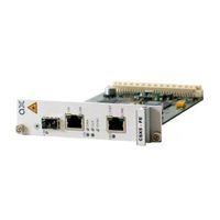
CSX5-FE
arcutronix CSX5-FE Modem Manuals
Manuals and User Guides for arcutronix CSX5-FE Modem. We have
1
arcutronix CSX5-FE Modem manual available for free PDF download: User Manual
arcutronix CSX5-FE User Manual (148 pages)
Brand:
arcutronix
| Category:
Modem
| Size: 3 MB
Table of Contents
About this Book
5
Chapters
5
Conventions
6
Release History
6
Referenced and Related Documents
8
Table of Contents
9
Chapter 0 Safety, Instructions, Statements
19
Safety Precautions
19
Power Precautions
19
Handling Precautions
19
Preventing Damage from Electrostatic Discharge
20
Card Protection
20
Grounding Procedure
20
Fibre Optic Precautions
21
Technical Instructions to User
21
Inspection
22
Commissioning
22
Cleaning
22
Quality
22
Repair
22
Table 0-1 Effects of Cleaning Liquids
22
Disposal and Recycling
23
CE Conformity
23
Electromagnetic Immunity Statement
23
Instructions to User
23
Electromagnetic Emissions Statements
23
Chapter 1 Abstract
25
CSX - Family Description
25
General
25
Remote Power Feeding
26
Nomenclature
26
Application Areas for the CSX
27
Ethernet First Mile
27
Table 1-1 Denominations
27
Figure 1-1 CSX EFM Application
28
Mobile Backhauling with Synce
28
Legacy Services
29
CSX Functions at a Glance
29
Figure 1-2 CSX Synce Application
29
Interfaces
29
Management
29
Housing and Power Supply
30
Order Information
30
Table 1-2 Order Matrix
30
Accessories
31
Housings and Cables
31
Sfps (Small Form-Factor Pluggable)
32
Table 1-3 Accessories Housing & Cables
32
Table 1-4 Accessories Sfps
32
Chapter 2 Getting Started
35
Delivered Parts
35
Preparing the Start-Up
35
Operating Conditions
35
Ambient Conditions
35
Table 2-1 Ambient Conditions
35
CSX Mounting
36
In SHX3-Family
36
In SRX10
36
In SRX3-Family
36
Airflow Requirements
37
Start-Up of the CSX
37
Switching on the Device
37
Power-Up Sequence
37
LED Start-Up
38
Configuration Access
38
Chapter 3 Hardware & Interfaces
39
Hardware Overview
39
Block-Diagram
39
Table 3-1 System Components
39
Figure 3-1 CSX Block-Diagram
40
Front Connectors and Leds
41
Csx5-Fe
42
Front Panel
42
Leds
42
Table 3-2 CSX5-FE Front View
42
Clock & Sync
43
On & Alm
43
Table 3-3 on & Alarm LED
43
Table 3-4 Clock & Sync Leds
43
Shdsl
44
Table 3-5 SHDSL Leds
44
Ethernet
45
Table 3-6 Ethernet Leds
46
Front Panel
47
Leds
47
Table 3-7 CSX5-V.24 Front View
47
Clock & Sync
48
On & Alm
48
Table 3-8 on & Alarm LED
48
Table 3-9 Clock & Sync Leds
48
Shdsl
49
Datacom User Port V.24
50
Table 3-10 SHDSL Leds
50
Pinouts
52
Shdsl
52
Table 3-11 V.24 Leds
52
10/100Basetx (RJ45)
53
Table 3-12 Pinning SHDSL RJ45 Connector
53
Table 3-13 SHDSL Standards
53
Table 3-14 Pinning Ethernet RJ45 Connector
54
Table 3-15 Ethernet Standards
54
100Base-X (SFP)
55
Datacom V.24 (DSUB-25, Menu and Submenu Entry|Read Eligibility|Write Eligibility)
55
Table 3-16 Pinning SFP Connector
55
Configuration of the V.24 Interface-Module
56
Connecting SHIELD and Digital Ground
56
Table 3-17 Pinning V.24 DB-25S Connector
56
CSX Backplane Connector
57
Figure 3-2 V.24 Interface Board, DCE Configuration
57
Figure 3-3 V.24 Interface Board, DTE Configuration
57
Power Supply
58
RS-232 Interface
58
Labels
58
Table 3-18 Transmission Rate of the RS-232 Interface
58
Figure 3-4 CSX Label: Example CSX5-FE
58
Chapter 4 Functionality
59
User & Line Ports
59
G.SHDSL Line-Interface
59
G.SHDSL Standard
59
STU-C and STU-R Mode
59
Crossing of Copper Pair and Lines
60
Figure 4-1 CSX Overview
60
Figure 4-2 CSX Overview with Repeater BRX1
60
Repeater
60
Configuration of the G.SHDSL Line-Port
61
Figure 4-3 Cross-Over of Copper Pair Within One Line
61
Figure 4-4 Cross-Over of Copper Lines in N-Wire Mode
61
EOC-Channel
62
Table 4-1 Supported EOC-Messages
62
Figure 4-5 SHDSL Loops for CSX
64
Figure 4-6 SHDSL Loops for CSX with Repeater
64
SHDSL Test-Loops
64
Ethernet Remote Bridge Functionality
65
Auto Negotiation
65
Basic
65
Speed and Duplex
65
Flow Control
66
Table 4-2 Settings Auto-Negotiation
66
Datacom V.24 Interface
67
Basic
67
DCE and DTE
67
Figure 4-7 DCE and DTE
68
Figure 4-8 DCE--DCE Configuration (Default)
68
Figure 4-9 DTE--DCE Configuration
68
Synchronous and Asynchronous Operation
68
Likely Problems When Using an EIA232 Interface
69
V.24 Test-Loops
70
Clocking Modes
70
Introduction
70
Figure 4-10 V.24 Loops
70
Figure 4-11 CSX Clock Modes
72
Restrictions of Usable Clock Modes (Ethernet)
73
Restrictions of Usable Clock Modes (V.24)
73
User & Access Administration
73
Access-Options to the CSX - Family
73
Local Access
73
Remote Access
74
User Administration
74
Locally Stored Users
74
Rules for Passwords
75
Rules for Usernames
75
Auto-Logout
75
Hardware-Based Auto-Logout
76
Miscellaneous
76
Firmware-Update
76
Remote SW-Update
76
Alarm Management
77
CSX Alarms
77
Maintenance Mode
77
Date & Time Settings
77
Event Monitoring
78
Alarm
78
Error
78
Info
78
Power Management
78
Figure 4-12 Flow Diagram Power Management
79
Rules of the Power Management
79
Performance Monitoring
80
Chapter 5 Control Software CSX & Gcli
81
General Information
81
Local RS-232 Interface
81
Access to Scx2E
81
Security Issues
82
Login Menu
82
Table 5-1 Default User-Names and Passwords
82
Information
83
Navigation
83
Edit Text-Entries
84
Exit
84
Page Update
84
Scrolling in Event-List
84
Select a Menu Entry
84
Overview to Keys
85
MENU Structure
86
Table 5-2 Overview to Key-Strokes
86
Main Menu
87
Figure 5-1 Main Menu
87
General System Information
88
Table 5-3 CSX Main Menu Options
88
Figure 5-2 General System Information Menu
88
Table 5-4 General System Information Menu
89
Administration
90
Figure 5-3 Administration Menu
90
Table 5-5 General System Information: Submenus
90
Table 5-6 Administration Menu
92
Table 5-7 Administration: Submenus
92
User Administration
92
Figure 5-4 User Administration Menu
93
Figure 5-5 Edit User Menu
94
Table 5-8 User Administration Menu
94
Line Interface (SHDSL)
95
Figure 5-6 Simple Line W/O Repeater
95
Figure 5-7 Line Interface (SHDSL) Menu (no Repeater Detected)
95
Figure 5-8 Line W 2X Repeaters
96
Figure 5-9 Line Interface Menu (2X Repeater Detected)
96
Table 5-10 Line Interface: Submenus
97
Table 5-9 Line Interface Menu
97
Figure 5-10 Performance Monitoring Menu
98
Performance Monitoring
98
Table 5-11 Performance Monitoring Menu
98
Configuration (Line Interface)
100
Figure 5-11 Configuration (Line Interface) Menu
100
Table 5-12 Configuration Menu (Line Interface)
100
Table 5-13 Entry of Datarate
102
Table 5-14 Entry of Datarate Ranges
102
Clock Mode
103
Ethernet Remote Bridge
103
Figure 5-12 Clock Mode Menu CSX5-FE
103
Datacom V.24 Interface
104
Table 5-15 Clock Mode Menu
104
User Interface
105
Ethernet Remote Bridge
105
Table 5-16 Clock Mode Menu
105
Figure 5-14 User Interface (Ethernet) Menu
106
Table 5-17 User Interface (Ethernet) Menu
106
Figure 5-15 Port Configuration (Ethernet) Menu
107
Port Configuration
107
Table 5-18 User Interface (Ethernet): Submenus
107
Datacom V.24 Interface
108
Table 5-19 Port Configuration (Ethernet) Menu
108
User Interface (V.24) Menu
109
Port Configuration
110
Table 5-20 User Interface (V.24) Menu
110
Table 5-21 User Interface (V.24): Submenus
110
Figure 5-17 Port Configuration (V.24) Menu
111
Table 5-22 Port Configuration (V.24) Menu
111
Alarms
112
Table 5-23 Entry of Interface Data Rate
112
Figure 5-18 Alarms Menu
113
Table 5-24 Alarms Menu
113
Alarms Details
114
Figure 5-19 Alarm Details Menu
114
Table 5-25 Alarms: Submenus
114
Table 5-26 Alarm Details Menu
115
Alarm Configuration
116
Figure 5-20 Alarm Configuration Menu
116
Table 5-27 Alarm Configuration Menu
116
Event Monitoring
117
Software Update
117
Local SW Update
117
Figure 5-21 Event Monitoring Menu
117
Start SW Update & Enter Boot-Loader
117
Figure 5-22 XY-Modem Started
118
Figure 5-23 XY-Modem Time-Out
118
File Transfer
118
Errors
119
Figure 5-24 File Transfer Successful
119
Figure 5-25 File Transfer Interrupted
119
File Transfer Interrupted or Erroneous
119
File Is Not Correct
120
Remote SW Update
120
Chapter 6 SNMP and Mibs
121
SNMP Access Generally
121
Management Information Bases (MIBS)
122
CSX - Family Mibs
122
Chapter 7 CSX - Family Menu-Tree
123
Menu-Structure (Directory-Tree) of CSX - Family
123
Table 7-1 Menu Tree CSX - Family
123
Appendix A Technical Specifications
135
CSX Hardware Specification
135
Hardware & Power
135
Table A-1 Mechanic and Environment
135
Table A-2 Security and EMC
136
Table A-3 Power Requirements
136
Interfaces
138
Table A-4 Number of Interfaces
138
Table A-5 Technical Data of the Interfaces
139
Μcontroller, Display & Clock
141
Table A-6 Display Functions
141
Table A-7 Μcontroller and Clock
141
CSX Software Specification
142
Table A-8 Technical Data of the CSX- Software
142
Loop Length and Data Rate for SHDSL
143
Table A-9 Loop Length and Data-Rate for SHDSL on a 0.4 TP (AWG26
143
Table A-10 Loop Length and Data-Rate for SHDSL on a 0.6 TP (AWB22
144
Appendix Ec EC Declaration of Conformity
145
Declaration of Conformity
145
Advertisement
Advertisement
Related Products
arcutronix CSX Series
arcutronix CSX5-V.24
arcutronix Categories
Modem
Media Converter
More arcutronix Manuals
Login
Sign In
OR
Sign in with Facebook
Sign in with Google
Upload manual
Upload from disk
Upload from URL