Table of Contents
Advertisement
Quick Links
Advertisement
Table of Contents

Subscribe to Our Youtube Channel
Summary of Contents for arcutronix CSX Series
- Page 1 CSX - Family Version 1.2...
- Page 2 cover-2 CSX User Guide...
- Page 3 CSX - G.SHDSL.bis (EFM) Copper Modem USER GUIDE Covered Variants of CSX - Family by this User Guide: CSX5-FE 1405 - 1001 CSX5-V.24 1405 - 1120 Covered Software Versions of CSX - Family by this User Guide: SW-Version: V 1_2_1 Boot-Loader: V 1_08 Part-Number (User-Guide):...
- Page 4 material.
-
Page 5: About This Book
Chapters Chapter 0, Safety, Instructions, Statements: Handling, precautions and warnings. Chapter 1, Abstract: Description of arcutronix MSS and the CSX Copper Converter. Chapter 2, Getting Started: Short form about installation, mounting and configuration of CSX-family. -
Page 6: Conventions
About this Book Conventions This manual uses the following text conventions to convey instructions and information: Normal text is written in Albany font. Commands and Arguments are done in Courier New. Notes, cautions, and tips use these conventions and symbols: NOTE: Means reader take note. - Page 7 About this Book Release History 2014-09-24 Version 1.0 Editor mjz First issue of the CSX User Guide. 2016-01-05 about-3...
-
Page 8: Referenced And Related Documents
Referenced and Related Documents [axManual_SCX2e_gs2] arcutronix GmbH (2014): SCX2e, User Manual. [axRefGuide_CLI_SCX2E] arcutronix GmbH (2014): SCX2e, Reference Guide for CLI. [ETSI TS 101 524] Technical Specification ETSI TS 101 524 (2003), Access transmission system on metallic access cables; Symmetric single pair high bitrate Digital Subscriber Line (SDSL). -
Page 9: Table Of Contents
List of Contents About this Book 1 Document Organization ............about-1 Chapters . - Page 10 Housing and Power Supply..........1-6 Order Information .
- Page 11 Datacom V.24 (DSUB-25, Menu and Submenu Entry|Read Eligibility|Write Eligibility) . . . 3-17 Configuration of the V.24 Interface-Module....... . . 3-18 Connecting SHIELD and Digital Ground.
- Page 12 Firmware-Update ............4-18 Remote SW-Update .
- Page 13 Alarms............... . . 5-32 Alarms Details.
- Page 14 toc-6 CSX User Guide...
- Page 15 List of Tables Table 0-1 Effects of Cleaning Liquids ..........0-4 Table 1-1 Denominations .
- Page 16 Table 5-9 Line Interface Menu ..........5-17 Table 5-10 Line Interface: Submenus .
- Page 17 List of Figures Figure 1-1 CSX EFM application ..........1-4 Figure 1-2 CSX SyncE application .
- Page 18 Figure 5-17 Port Configuration (V.24) Menu ........5-31 Figure 5-18 Alarms Menu .
-
Page 19: Chapter 0 Safety, Instructions, Statements
Chapter 0 Safety, Instructions, Statements Safety Precautions The following sections provide the safety precautions for the supplied device. You must always observe the power precautions for the device. You must follow all warning notes to ensure that the procedures are performed safely. You must follow all caution notes to ensure that the device is operated correctly. -
Page 20: Preventing Damage From Electrostatic Discharge
Safety, Instructions, Statements Safety Precautions • Ensure sufficient cooling of the device. • Prevent loose items from falling into the device. • Avoid damage to components when installing or setting switches or jumpers of the device. • Always place protective covers on all fibre optic cables and connectors that are not in use to prevent breakage and contamination. -
Page 21: Fibre Optic Precautions
Safety, Instructions, Statements Technical Instructions to User Caution: Do not place the spare component on the top of the chassis, rack, or on a metal table. Either action could cause severe damage to the spare. • Be aware of weather conditions. Cold weather increases the likelihood of static electricity build-up. -
Page 22: Inspection
This product is manufactured to the arcutronix quality standards Repair There are no repairable parts in the device. Defective parts must be sent to arcutronix for repair. The power supplies of a device may contain fuses. Blown-up mains fuses must be replaced by fuses of the same type and the same ratings. Using repaired fuses or short-circuit the fuse holder are not permitted. -
Page 23: Disposal And Recycling
For more detailed information about recycling contact your local city office, your waste disposal service or where you purchased the product. CE Conformity arcutronix products complies with the European standard regulation. They are tested to the Council guideline for harmonizing the legal regulations of the member states on electromagnetic compatibility. - Page 24 Safety, Instructions, Statements Electromagnetic Emissions Statements have to be covered with a blanking plate. The chassis must be bonded to earth. This is usually achieved by installing the power cord to the chassis. An extra earth terminal may be provided. If this device is used in a residential setting, resulting interference must be corrected by the user.
-
Page 25: Chapter 1 Abstract
Chapter 1 Abstract CSX - Family Description General The CSX - G.SHDSL.bis (EFM) Copper Modem is a flexible modem to transport a wide bunch of different interfaces over long haul copper infrastructure by the use of SHDSL technique as recommended in ITU-T G.SHDSL ([ITU-T G.991.2]). It offers bandwidth capability up to 20 Mbps and is based on a modular design to achieve an efficient and flexible concept. -
Page 26: Remote Power Feeding
Remote management capability makes it easy to configure, operate and maintain units, which are even far away from the ISP’s management access point. Moreover, as part of arcutronix’s Multi Service Platform, the CSX - Family benefits from the future-proof system architecture and management features. This includes various chassis and housing options with optional redundant power supplies and centralized management via a rack agent (SCX2e). -
Page 27: Application Areas For The Csx
The CSX offers transport and conversion of several service interface onto a copper network. All this gives a wide bouquet of combinations, which will not all available or mentioned in the order matrix. Please check with your local arcutronix partner for your needs and possible options. -
Page 28: Mobile Backhauling With Synce
Abstract CSX - Family Description The PHY aggregation function (PAF) allows channel bundling of EFM PHYs to either increase the data rate or the maximum achievable loop length. The incoming packets are transported along the (bundle of) SHDSL line(s). To reduce the required bandwidth, the FCS checksum of each packet is removed at the ingress and recalculated at the egress. -
Page 29: Legacy Services
• Local and remote loop-back, BER test and performance monitoring on line and interface ports. Management • Fully management configuration via – RS232 / VT100 in the SHX3 single-slot housing or with the arcutronix system controller and agent card SCX2e. 2016-01-05... -
Page 30: Housing And Power Supply
• Power input (5VDC) via backplane connector Order Information NOTE: All order matrices will be regularly updated. Asked your arcutronix representative for the latest publications. The order table shows the available variants of the CSX - G.SHDSL.bis (EFM) Copper Modem. Further options are possible on request. -
Page 31: Accessories
Order Information Accessories Housings and Cables The arcutronix’ Multi Service Platform offers a range of accessories for an easy and space saving installation of your device into 19” cabinets or as desktop / wall-mount installation. Table 1-3 Accessories Housing & Cables Art.- No. -
Page 32: Sfps (Small Form-Factor Pluggable)
1 lasers and are compliant with [IEC 60825-1]. CSX does support all optical modules, which are designed according the SFP MSA. For safe operation, arcutronix recommends the SFPs below. Please ask for special types, if required. Table 1-4 Accessories SFPs... - Page 33 Abstract Order Information Table 1-4 Accessories SFPs (continued) Short Name Description SFP-155-S13-15 Optical SFP Interface Module: 1310nm SM FO; Fast E, 155 Mbps transceiver; pluggable SFP footprint; LC connector; 15km SFP-155-S13-40 Optical SFP Interface Module: 1310nm SM FO; Fast E, 155 Mbps transceiver;...
- Page 34 Abstract Order Information 1-10 CSX User Guide...
-
Page 35: Chapter 2 Getting Started
Chapter 2 Getting Started For the start-up of the CSX please follow the directions in this chapter. You must keep the operating conditions specified for the devices. In the following read about the start-up preparation, the start-up itself, and the possibility to automate the start-up. -
Page 36: Csx Mounting
Getting Started Preparing the Start-up Table 2-1 Ambient Conditions Input Voltage +5V DC Power Consumption < 4 VA i. Depends on the given variant and used SFPs. CAUTION: If operating limits are exceeded, malfunctions and permanent damage to the equipment may result. NOTE: In order to operate the various interfaces, please ensure that the plugs are firmly engaged in the sockets. -
Page 37: Airflow Requirements
Getting Started Start-up of the CSX 2. The CSX is mounted in horizontal way, the handle must be on the right side. 3. Insert the CSX into the SHX3. 4. Fix the CSX to the housing using the provided screws. 5. -
Page 38: Led Start-Up
1. local access point (RS232/VT100), which is accessible in the SHX3 single-slot housing (Chapter 5, Control Software CSX & gCLI), or 2. centralized/remote access point via the arcutronix system controller and agent card SCX2e. The local access point is good for stand-alone installations and offers an easy to use VT100 management interface. -
Page 39: Chapter 3 Hardware & Interfaces
Chapter 3 Hardware & Interfaces This chapter provides information about the hardware of CSX - G.SHDSL.bis (EFM) Copper Modem. This consist of block-diagram and a detailed description of all external interfaces and function indicators. The CSX is a compact unit. All external connection points for data lines and some con- trol elements are accessible on the front panel. -
Page 40: Figure 3-1 Csx Block-Diagram
Hardware & Interfaces Hardware Overview Table 3-1 System Components (continued) Component Description Connector to The flexible concept of CSX provides the option to plug Interface-Module different modules. with the help of these modules, other interfaces than Ethernet can be realized. the IM-connector is proprietary to ax. -
Page 41: Front Connectors And Leds
Hardware & Interfaces Front Connectors and LEDs connections (front and backplane) are available to get in conntact. Via several buses, the LCP is connected to all other devices to supervise and control them. The purple components build the external (user-)interface in the “FE” (“Fast Ethernet”) variants. -
Page 42: Csx5-Fe
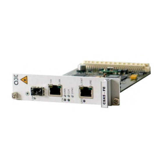
Hardware & Interfaces Front Connectors and LEDs CSX5-FE Front Panel Table 3-2 provides information on the connectors, indicators, and control elements of the CSX System Controller: 5-FE Table 3-2 CSX Front View View Details Mounting screw in SRX. 1x 100FX User Port + 1x LINK-LED. 1x 10/100BaseT User Port, 2x integrated LEDs. -
Page 43: On & Alm
Hardware & Interfaces Front Connectors and LEDs ON & ALM The ON-LED is used for power-supply indication, while the ALM-LED shows the alarm status of the device. After Power-On of the device, both LEDs will be on. Table 3-3 ON & Alarm LED ON-LED Display states of the LED: No supply voltage. -
Page 44: Shdsl
Hardware & Interfaces Front Connectors and LEDs Table 3-4 Clock & Sync LEDs (continued) off | on Remote clock mode. This is the (default) clock mode for STU-R devices. on | on Internal clock mode. This is the default clock mode for STU-C devices, when SyncE is not enabled. -
Page 45: Ethernet
Hardware & Interfaces Front Connectors and LEDs Table 3-5 SHDSL LEDs (continued) LINE-LED Display states of the LED: SHDSL line down and no activating in progress. flashing SHDSL line is activating. blinking SHDSL line is established on segment 1. 1.5Hz The SHDSL peer (STU-R for STU-C and vice versa) is not detected, yet. -
Page 46: Table 3-6 Ethernet Leds
Hardware & Interfaces Front Connectors and LEDs The fibre port is a SFP-slot plus one LED. The label of the LED is LNK. This LED is only used in fibre mode. Table 3-6 Ethernet LEDs 100-LED Display states of the LED: The Ethernet port speed is 10Mbps (10BaseT) or the port is in fibre mode. -
Page 47: Front Panel
Hardware & Interfaces Front Connectors and LEDs CSX5-V.24 Front Panel Table 3-7 provides information on the connectors, indicators, and control elements of the CSX System Controller: 5-V.24 Table 3-7 CSX Front View View Details Mounting screw in SRX. 1x V.24-User Port + 1x Mode-LED. 4x Status LEDs. -
Page 48: On & Alm
Hardware & Interfaces Front Connectors and LEDs ON & ALM The ON-LED is used for power-supply indication, while the ALM-LED shows the alarm status of the device. After Power-On of the device, both LEDs will be on. Table 3-8 ON & Alarm LED ON-LED Display states of the LED: No supply voltage. -
Page 49: Shdsl
Hardware & Interfaces Front Connectors and LEDs Table 3-9 Clock & Sync LEDs (continued) off | on Remote clock mode. This is the (default) clock mode for STU-R devices. on | on Internal clock mode. This is the default clock mode for STU-C devices, when SyncE is not enabled. -
Page 50: Datacom User Port V.24
Hardware & Interfaces Front Connectors and LEDs Table 3-10 SHDSL LEDs (continued) flashing SHDSL line is activating. blinking SHDSL line is established on segment 1. 1.5Hz The SHDSL peer (STU-R for STU-C and vice versa) is not detected, yet. SHDSL line is established end-to-end. UKS-LED Display states of the LED: SHDSL start-up did not happen, yet. - Page 51 Hardware & Interfaces Front Connectors and LEDs Five LEDs show the configuration (DCE vs. DTE) and the status of the V.24 port. Table 3-11 V.24 LEDs DCE-LED Display states of the LED: Datacom user port (V.24) operates in DTE mode. The pinning is according to DTE.
-
Page 52: Pinouts
Hardware & Interfaces Front Connectors and LEDs Table 3-11 V.24 LEDs (continued) blinking Facility Loop on V.24 interface is active. 1,5Hz DCD-LED Display states of the LED: Indicator for DCD-signal: DCE-mode: the DCD-LED is on, as soon as the device sets the DCD signal active. -
Page 53: 10/100Basetx (Rj45)
Hardware & Interfaces Front Connectors and LEDs The pin-assignment of the RJ45 is as follows: Table 3-12 Pinning SHDSL RJ45 Connector RJ45 Assignment TIP DSL4 RING DSL4 TIP DSL2 1: TIP DSL1 1: RING DSL1 RING DSL2 TIP DSL3 RING DSL3 TIP/RING crossing and TP-Cross-Connect are supported. -
Page 54: Table 3-14 Pinning Ethernet Rj45 Connector
Hardware & Interfaces Front Connectors and LEDs according to [IEEE 802.3].The connector is a RJ45 plug with 2 LEDs, which indicate speed, link and activity. The pin-assignment of the RJ45 is as follows: Table 3-14 Pinning Ethernet RJ45 Connector RJ45 Assignment NOTE: If the CSX detects an SFP in a combo-port, the adjacent copper-port will be... -
Page 55: 100Base-X (Sfp)
Hardware & Interfaces Front Connectors and LEDs 100Base-X (SFP) The CSX5-FE provides one optical Ethernet interfaces as part of a combo-port. The device supports 100 Mbit/s, full-duplex, only. The protocol is according to [IEEE 802.3].The connector is according [INF-8074i] and [SFP MSA]: Table 3-16 Pinning SFP Connector Assignment Electrical Socket:... -
Page 56: Configuration Of The V.24 Interface-Module
Hardware & Interfaces Front Connectors and LEDs cations. The configuration and corresponding pin-swapping is done by jumpers. There is no SW or management based re-configuration possible Table 3-17 Pinning V.24 DB-25S Connector Signal Direction Direction Shield Ground EXTCLK rest not used Configuration of the V.24 Interface-Module The V.24-I/F can be operated in DCE or DTE mode (see “DCE and DTE”... -
Page 57: Csx Backplane Connector
Figure 3-3 V.24 Interface Board, DTE Configuration CSX Backplane Connector The CSX series has a connector on the rear-side offering the possibility to use the devices either in 19-inch racks or desktop housing. On the connector, the ports for local management (RS-232), power supply and rack-management are placed. -
Page 58: Rs-232 Interface
Hardware & Interfaces Labels RS-232 Interface The internal management port of the CSX is placed on the card’s bus connector at the rear side of the unit. You need an agent card in the chassis or a single-slot housing with management connector. -
Page 59: Chapter 4 Functionality
Chapter 4 Functionality User & Line Ports G.SHDSL Line-Interface G.SHDSL Standard Single-Pair high-speed digital subscriber line (SHDSL) is a telecommunications tech- nology for Digital Subscriber Line (DSL) subscriber lines. It describes a transmission method for signals on copper pair lines, being mostly used in access networks to con- nect subscribers to Telephone exchanges or POP Access Points. -
Page 60: Repeater
Functionality User & Line Ports Figure 4-1 CSX Overview During start-up, the two units (LTU and NTU) find the best filters to get optimised throughput for the given infra-structure. The principal functions are: – symbol timing generation and recovery; – coding and decoding; –... -
Page 61: Configuration Of The G.shdsl Line-Port
Functionality User & Line Ports Note: Crossover between lines is only possible for CSX10 (lines 1/2) and CSX20 (lines 1/2/3/4). Please see the two next figures for details on the mentioned wiring mismatches. Figure 4-3 Cross-Over of Copper Pair within one Line Figure 4-4 Cross-Over of Copper Lines in n-wire mode A mismatch of pairs AND lines can not be resolved by the CSX - Family. -
Page 62: Eoc-Channel
Functionality User & Line Ports • STR-C (LTU) or STU-R (NTU) mode. Both ends must have different setting for mode. The green LED in the RJ45 connector shows LT mode when lighting. • The CSX - Family supports rate-adaptive transmission. The date rate is adjusted automatically via the STU-C device to find the best possible transmission rate. - Page 63 Functionality User & Line Ports Table 4-1 Supported EOC-Messages Initiating Message Type Remark Unit [ITU-T G.991.2], chapter 9.5.5.7.9 STU-R Configuration STU-C Request – Management Dwl-ZWR-IMG-Request BRX-DL Proprietary Message. Used for SW-Download via EOC. Dwl-ZWR-IMG-Status- BRX-DL Proprietary Message. Used for Request SW-Download via EOC.
-
Page 64: Shdsl Test-Loops
Functionality User & Line Ports SHDSL Test-Loops The cause of transmission problems can be localised by activation of test loops. One can check the SHDSL transmission line and all components connected, when a loop back is activated. During activation of the test loop the incoming data signal is re-trans- ferred into the opposite direction. -
Page 65: Ethernet Remote Bridge Functionality
Functionality User & Line Ports Ethernet Remote Bridge Functionality Basic The CSX-FE version with Ethernet bridge is able to connect two networks over a long distance. It supports automatic detection of the connection speed (10/100 Mbps auto- sensing) and also the transmission of jumbo frames up to 2048 bytes frame size. The CSX-FE provides interconnection and mapping functionality between Ethernet Systems and WAN Time-Division Multiplexed (TDM) systems. -
Page 66: Flow Control
Functionality User & Line Ports Please see table below for the possible settings and the resulting behaviour. Table 4-2 Settings Auto-Negotiation Result Setting (Port Speed) Speed Duplex Remark Automatic Full or Half Full Auto-neg takes 10 or 100 Mbps place; no limitations are Duplex given. -
Page 67: Datacom V.24 Interface
Functionality User & Line Ports The usage of PAUSE frames is defined by IEEE 802.3x and uses MAC Control frames to carry the PAUSE commands. Datacom V.24 Interface Basic The V.24 interface is mainly used for EIA-232 standard interface. In the early 1960s, a standards committee, today known as the Electronic Industries Association, developed a common interface standard for data communications equipment. -
Page 68: Synchronous And Asynchronous Operation
Functionality User & Line Ports This drawing shows the orientation and connector types for DTE and DCE devices: Figure 4-7 DCE and DTE The CSX5-V.24 is acting as a modem and so it is configured as DCE by default on both ends of the SHDSL line to allow the transport of data. -
Page 69: Likely Problems When Using An Eia232 Interface
Functionality User & Line Ports The CSX5-V.24 does support both modes, without any additional configuration. Self-detecting of clock-rates in synchronous mode or Baudrate in asynchronous mode makes is needless to configure anything. The detected mode on both sides much match in a DCE--DCE-scenario (see above), otherwise an alarm is raised. In the DTE--DCE scenarios (see above) the DTE (STU-C) forwards the clock information to the remote side. -
Page 70: V.24 Test-Loops
Functionality Clocking Modes V.24 Test-Loops The cause of transmission problems can be localised by activation of test loops. Two loops are available for the V.24 user interface: • Facility Loop, and • Terminal Loop. Figure 4-10 V.24 Loops In case one of the two loops is activated, this is indicated by the V.24 LEDs (see “V.24 LEDs”... - Page 71 Functionality Clocking Modes The clock source for the SHDSL line is taken from the user interface’s External incoming clock information. Not all variants of user interfaces do have the ability to derive the clock from. The egress clock for the user interface is also derived from the incoming clock information (formally called “Single Clock Mode”).
-
Page 72: Figure 4-11 Csx Clock Modes
Functionality Clocking Modes Figure 4-11 CSX Clock Modes 4-14 CSX User Guide... -
Page 73: Restrictions Of Usable Clock Modes (Ethernet)
Functionality User & Access Administration Restrictions of Usable Clock Modes (Ethernet) For standard Ethernet connections, the external clock is not defined and not available. An onboard 25MHz oscillator is clock source for the PHY. In case, synchronous Ethernet (SyncE) is available, the device can be synchronized upon the incoming clock at the LTU-side (STU-C) and the clock is identically provided at the remote end NTU (STU-R). -
Page 74: Remote Access
Functionality User & Access Administration – See Chapter 5, Control Software CSX & gCLI. – Settings: 57600kBaud, 8N1. • Extended management access in the ax 19-inch rack via the central management blade SCX2e. – SNMP, http, https, and ssh are provided. Remote Access A inband management from STU-C to STU-R side is available to have single access point for the complete modem link. -
Page 75: Rules For Usernames
Functionality User & Access Administration NOTE: At least one user must be available on the device. In case the last user shall be deleted, the device will refuse to do so. Rules for Usernames When a new user has to added to the user-list, some simple rules must be considered: •... -
Page 76: Hardware-Based Auto-Logout
• Y-Modem (serial) in the desktop housing • via agent-card in the 19-inch rack. The update-file has the extension “*.pkg” and is a special arcutronix file format. It is secured by a checksum and other mechanism to make sure only correct files will be accepted for firmware update. -
Page 77: Alarm Management
The maintenance mode can only be entered, when a user with ’admin’ privileges is logged into the device. This way of securing the maintenance mode makes sure, only admin users can entered the mode, and only arcutronix can allow to do proceed. Date & Time Settings The CSX - Family does have an internal clock, which can be set by either user or via SCX2e. -
Page 78: Event Monitoring
• The <ERROR>-entry reports severe failures. Power Management The intelligent arcutronix Multi Service System power management is to prevent a sys- tem-fail in case a new line-card is plugged as well as a permanent check on the volt- age-level at each slot. -
Page 79: Rules Of The Power Management
Rules of the Power Management • If the remaining power is not sufficient in the arcutronix Multi Service System, a rack card, e.g. agent or modem card, will not power up. • The decision whether a unit will be powered up or not is taken, when a new card is inserted into the chassis (SRX) or if the whole system is powered up simultaneously. -
Page 80: Performance Monitoring
Functionality Miscellaneous • On the other side, if the card has been rejected to start, it will stay in the pre-started mode and checks permanaetly the voltage on the bus. As soon as enough power is available, it will “grep” it and start. •... -
Page 81: Chapter 5 Control Software Csx & Gcli
Chapter 5 Control Software CSX & gCLI In this chapter the graphical Command Line Interface (gCLI), which is a very easy way to configure and monitor the unit, will be presented. In spite to a classical CLI, one does not have the need to learn cryptic instruction sets and has to move in thousands of sub-directories. -
Page 82: Security Issues
Control Software CSX & gCLI Security Issues Security Issues The serial port is only accessible via direct contact to the 9-pin D-sub socket (DE-9S) but it might be that other persons than the intended ones get connection and will see the login screen. -
Page 83: Information
Control Software CSX & gCLI Login Menu The Login screen is shown in the figure below. Enter user-name and password and then select “Login” and press <enter>. ** CSX5 Login 09:05:04 User ________________________________________ Password ________________________________________ Login The password will not be displayed. Each character will be replaced by an asterisk (*). An error message will be displayed for any unsuccessful login. -
Page 84: Select A Menu Entry
Control Software CSX & gCLI Login Menu Select a menu entry All menu lines which are accessible by the cursor are shown in a different manner than un-accessible lines . Select any menu text of interest by cursor-up/ -down keys and press the Enter key. -
Page 85: Overview To Keys
Control Software CSX & gCLI Login Menu Overview to keys Table 5-2 provides information on the different keys for navigating and editing. Table 5-2 Overview to key-strokes Action Remark Enter (CR) Selects the chosen entry. Depending on the type of entry, different actions will happen: •... -
Page 86: Menu Structure
Control Software CSX & gCLI Login Menu Table 5-2 Overview to key-strokes (continued) Action Remark HOME Cursor jumps to begin of field. CTRL-a Cursor jumps to end of field. CTRL-e ESCAPE Cancel entry and leave line without change. CTRL-c CTRL-k Delete all characters from cursor to end-of-line. -
Page 87: Main Menu
Control Software CSX & gCLI Main Menu Main Menu After the login, the Main menu will be displayed, which provides a general overview of the menu structure. ** CSX5 11:47:18 General System Information Administration Line Interface (SHDSL) Clock Mode User Interface (Ethernet) Alarms Event Monitoring Logout... -
Page 88: General System Information
Device Type CSX5 Order No. 1405-1000 Serial Number 2014006366 Article Revision Hardware Revision 140510/000 Date of Production 01.09.2014 Manufacturer arcutronix GmbH Vendor ID UN341185881 MAC Addr 00:1E:16:00:01:01 Bootloader Version V1.08 FPGA Version Software Version V 1_2_1 User Interface V.24 Remote System Information Go up i. -
Page 89: Table 5-4 General System Information Menu
Manufacturer of the Device Display arcutronix GmbH (normally arcutronix GmbH). Vendor ID International unique ID for Display UN341185881 arcutronix GmbH. Issuing agency is Dun & Bradstreet using D-U-N-S (R). MAC Address Displays the MAC address of the Display 00:1E:16:aa:bb:c user port. -
Page 90: Administration
Control Software CSX & gCLI Administration The following submenu is available: Table 5-5 General System Information: Submenus Submenu Description Remote System Displays all the above mentioned information for the STU-R. Information This submenu is only visible on STU-C! As long as the SHDSL line is not established, yet, the information in the submenu will be empty. - Page 91 Control Software CSX & gCLI Administration Table 5-6 Administration Menu Parameter Description Format Default Contact Person Description/comment of the Display/Input < ... > device. (up to 32 characters) Device Location Description/comment of the Display/Input < ... > device. (up to 32 characters) Device Name Description/comment of the...
-
Page 92: User Administration
Control Software CSX & gCLI Administration Table 5-6 Administration Menu (continued) Parameter Description Format Default Remote Update Displays the status of SW update Status on the remote device. This entry is only visible on STU-C! Maintenance Pulldown menu to start the PullDown Menu Cancel Mode... -
Page 93: Figure 5-4 User Administration Menu
Control Software CSX & gCLI Administration ** CSX5 / Administration / User Administration 13:35:05 Username admin Edit User 1 Username service Edit User 2 Username monitor Edit User 3 Username ________________________________________ Edit User 4 Change current Password ________________________________________ Go up Figure 5-4 User Administration Menu 2016-01-05 5-13... -
Page 94: Table 5-8 User Administration Menu
Control Software CSX & gCLI Administration When a user’s data-base shall be changed, select “Edit User x” and press enter. A new menu is displayed, where name, password and access-level can be changed: ** CSX5 / Administration / User Administration / Edit User 1 13:37:50 Username admin... -
Page 95: Line Interface (Shdsl)
Control Software CSX & gCLI Line Interface (SHDSL) Line Interface (SHDSL) The Line Interface menu gives access to the actual parameters of the (established) link, as well as some performance monitoring data. As soon as the link is established, an overview is presented about the link: •... -
Page 96: Figure 5-8 Line W 2X Repeaters
Control Software CSX & gCLI Line Interface (SHDSL) The noise margin (NM) and line attenuation (LA) is shown for both ends of the link (here link = segment). The shown values at the two ends can be equal, but this is not always the case, as the noise and disturbance on the line may be different for the two ends. -
Page 97: Table 5-9 Line Interface Menu
Control Software CSX & gCLI Line Interface (SHDSL) Table 5-9 provides information about the options. Table 5-9 Line Interface Menu Parameter Description Format Port Name Name for this port. It can be free advised by user. String Current DSL Summary for the SHDSL line: Display Status •... -
Page 98: Performance Monitoring
Control Software CSX & gCLI Line Interface (SHDSL) Performance Monitoring The Performance Monitoring menu for the Line Interface (SHDSL) presents the per- formance. ** CSX5 / Line Interface (SHDSL) / Performance Monitoring 15:51:40 Performance Monitoring Interval Local Monitoring Last Update 15:51:39 Current DSL Status Link Up (5696kbit/s, PAM32) - Page 99 Control Software CSX & gCLI Line Interface (SHDSL) Table 5-11 Performance Monitoring Menu (continued) Parameter Description Format Erroneous Counter of seconds, in which an error was detected Display Seconds (ES) on the SHDSL line. Severely Errored Counter of seconds, in which severe errors were Display Seconds (SES) detected on the SHDSL line.
-
Page 100: Configuration (Line Interface)
Control Software CSX & gCLI Line Interface (SHDSL) Configuration (Line Interface) The SHDSL line can be configured in some basic options. Normally the default settings are correct and no change is required. Any changes made on the STU-C side is trans- ferred to the remote end, even when the SHDSL line is not established yet! ** CSX5 / Line Interface (SHDSL) / Configuration 16:17:52... - Page 101 Control Software CSX & gCLI Line Interface (SHDSL) Table 5-12 Configuration Menu (Line Interface) (continued) Parameter Description Format DSL Data Rate Menu to enter the data rate Enter value Auto (speed) on the DSL link. A wide range of entries is possible here, see table below.
-
Page 102: Table 5-13 Entry Of Datarate
Control Software CSX & gCLI Line Interface (SHDSL) The configuration of the DSL data-rate can be either automatic (AUTO), a fixed data-rate or a range in which the data-rate must be. If the modem cannot establish the link with the desired value or in the defined range, the link will not be established. The entry of the value and/or range can be done in several formats. -
Page 103: Clock Mode
Control Software CSX & gCLI Clock Mode Clock Mode The clock mode defines the source of the unit in meaning of the SHDSL clock and/or user-interface clock. See “Clocking Modes” on page 4-12 for details. The clock mode can only be configured on the STU-C. The STU-R is always configured to operate in “remote”... -
Page 104: Datacom V.24 Interface
Control Software CSX & gCLI Clock Mode Table 5-15 Clock Mode Menu Parameter Description Format Clockmode PullDown-Menu Internal Configuration of the clock mode. • Internal • SyncE i. The Clock Mode can only be configured on a STU-C device. The STU-R device is always config- ured from the far end. -
Page 105: User Interface
Control Software CSX & gCLI User Interface Table 5-16 Clock Mode Menu Parameter Description Format Clockmode Read-Only Internal Configuration of the clock mode. • Internal i. The Clock Mode can only be configured on a STU-C device. The STU-R device is always config- ured from the STU-C side. -
Page 106: Table 5-17 User Interface (Ethernet) Menu
Control Software CSX & gCLI User Interface ** CSX5 / User Interface (Ethernet) 16:51:37 -- Local Port Information -- Port Name Port 1 Media Mode Copper Mode Port Status RJ45: Link Down Auto Crossover No Crossover Port Configuration -- Remote Port Information -- Port Name Port 1 Media Mode... -
Page 107: Port Configuration
Control Software CSX & gCLI User Interface The following submenus are available: Table 5-18 User Interface (Ethernet): Submenus Submenu Description Port This menu allows to configure the local Ethernet port. Configuration Remote Port This menu allows to configure the remote Ethernet port. Configuration Note: Only possible on the STU-C device. -
Page 108: Datacom V.24 Interface
Control Software CSX & gCLI User Interface Table 5-19 Port Configuration (Ethernet) Menu Parameter Description Format Admin Status Enables or disables the port. PullDown-Menu Enabled • Enabled • Disabled MTU Size Two values can be selected for PullDown-Menu 1518 Maximum Transmission Size on •... -
Page 109: User Interface (V.24) Menu
Control Software CSX & gCLI User Interface ** CSX5 / User Interface (V.24) 16:51:37 Port Name V.24 Port Type Current Status Async Mode Interface Data Rate 19200bit/s (internal) Loopback Port Configuration -- Remote Port Information -- Port Name V.24 Port Type Current Status Async Mode... -
Page 110: Port Configuration
Control Software CSX & gCLI User Interface Table 5-20 User Interface (V.24) Menu (continued) Parameter Description Format Detected Indicates the detected speed of Display no default Interface Data the V.24 interface. Rate This entry is visible, when the CSX-device is acting as clock-sink from the interface (in DTE-mode). -
Page 111: Table 5-22 Port Configuration (V.24) Menu
Control Software CSX & gCLI User Interface Port Configuration ** CSX5 / User Interface (V.24) / Port Configuration 16:59:12 Port Name V.24 Port Admin Status Enabled Mode Asynchron Interface Data Rate 19200 Go up Figure 5-17 Port Configuration (V.24) Menu Table 5-22 Port Configuration (V.24) Menu Parameter Description... -
Page 112: Alarms
Control Software CSX & gCLI Alarms The configuration of the serial data-rate can be done in several formats. The example below is given for the data-rate 115200bit/s: Table 5-23 Entry of Interface Data Rate Format 115200bit/s value only 115200 value and prefix 115k Note: Only integer values possible. -
Page 113: Table 5-24 Alarms Menu
Control Software CSX & gCLI Alarms ** CSX5 / Alarms 17:12:42 Current Alarm Status Active Current Alarms Ethernet Link, Rem. Ethernet Link Alarm Details Remote Alarm Details Alarm Configuration Remote Alarm Configuration Go up Figure 5-18 Alarms Menu Table 5-24 Alarms Menu Parameter Description Format... -
Page 114: Alarms Details
Control Software CSX & gCLI Alarms Table 5-25 Alarms: Submenus (continued) Submenu Description Alarm This menu allows to configure the local alarm handling. Configuration Remote Alarm This menu allows to configure the remote alarm handling. Configuration Note: Only possible on the STU-C device. Alarms Details The Alarm Details list all possible alarms and the actual status of the alarms. -
Page 115: Table 5-26 Alarm Details Menu
Control Software CSX & gCLI Alarms Table 5-26 Alarm Details Menu Parameter Description Format System Status Display to show the actual alarm status of the device. Display Alarm Note: This alarm is available in all variants of CSX - Family. Clear System Pulldown menu to clear the mentioned alarm. -
Page 116: Alarm Configuration
Control Software CSX & gCLI Alarms Alarm Configuration The Alarm Configuration menu allows to enable and disable the available alarms. A dis- abled alarm will not raise and action like LED-light, relay or traps in the SCX2e agent card. ** CSX5 / Alarms / Alarm Configuration 17:20:53 System Status Alarm Config Enabled... -
Page 117: Event Monitoring
Control Software CSX & gCLI Event Monitoring Event Monitoring All events are stored in a list, which can be viewed in this menu. The list has a capacity of 99 entries. In case the onboard storage for the event-list is full, the oldest event is removed from the list to free buffer space. -
Page 118: File Transfer
The device will detect automatically the selected protocol option. Which proto- col your terminal program supports is not part of the manual. arcutronix has tested several terminal programs (TeraTerm, putty, HyperTerm, etc.). For TeraTerm, the command to start an YMODEM transfer is •... -
Page 119: Errors
Control Software CSX & gCLI Software Update • e.g. csx5-V1_0_0d.pkg The file transfer will take ~40 seconds. After the transfer, the file is checked, whether it really fits and can be used (error check etc.). If everything is fine, the device will restart again and the boot-loader will start the new software. -
Page 120: File Is Not Correct
Control Software CSX & gCLI Software Update File is not correct A file, which does not fit onto a CSX will not be accepted by the boot-loader. The file transfer is interrupted and the transfer of the correct file is expected. Remote SW Update A SW update from local (STU-C) to remote (STU-R) is possible. -
Page 121: Chapter 6 Snmp And Mibs
Chapter 6 SNMP and MIBs This chapter provides information on the SNMP and the management information bases (MIBs) used by the CSX - Family. The CSX - Family does not have an SNMP-agent on-board. SNMP access is only pos- sible in cooperation with an ax main agent SCX2e. See [axManual_SCX2e_gs2] for more details about SNMP than it is presented here after. -
Page 122: Management Information Bases (Mibs)
This is no malfunction but a feature of your software. CSX - Family MIBs You can download the MIB from the ax extranet (www.arcutronix.com/customer): Login: User = p49170644-0 Password = 1qayxsw2... -
Page 123: Chapter 7 Csx - Family Menu-Tree
Chapter 7 CSX - Family Menu-Tree The CSX - Family offers several ways to manage the unit, as written in the chapters before. These different ways do not use each a different management core, but there is one common core in use. The different ways of management are different interfaces to this common managment core. - Page 124 CSX - Family Menu-Tree Menu-Structure (Directory-Tree) of CSX - Family Table 7-1 Menu Tree CSX - Family (continued) Menu and Submenu Entry Read Eligibility Write Eligibility MAC Addr VIEW_ALL Bootloader Version VIEW_ALL FPGA Version VIEW_ALL if DEP #2 Software Version VIEW_ALL Software Details VIEW_ALL if...
- Page 125 CSX - Family Menu-Tree Menu-Structure (Directory-Tree) of CSX - Family Table 7-1 Menu Tree CSX - Family (continued) Menu and Submenu Entry Read Eligibility Write Eligibility Device Name VIEW_ALL WRITE_SERVICE Current Date VIEW_ALL WRITE_SERVICE Current Time VIEW_ALL WRITE_SERVICE >User Administration ACCESS_ALL ** CSX5 / Administration / User Administration ACCESS_ALL...
- Page 126 CSX - Family Menu-Tree Menu-Structure (Directory-Tree) of CSX - Family Table 7-1 Menu Tree CSX - Family (continued) Menu and Submenu Entry Read Eligibility Write Eligibility -> [ Enabled / Disabled ] Username VIEW_SERVICE >Edit User 4 ACCESS_SERVIC ** CSX5 / Administration / User Administration / Edit ACCESS_ALL User 4 Username...
- Page 127 CSX - Family Menu-Tree Menu-Structure (Directory-Tree) of CSX - Family Table 7-1 Menu Tree CSX - Family (continued) Menu and Submenu Entry Read Eligibility Write Eligibility SRU-1 VIEW_ALL if DEP #7 Noise Margin / Line Attenuation VIEW_ALL if DEP #8 Noise Margin / Line Attenuation VIEW_ALL if DEP #9...
- Page 128 CSX - Family Menu-Tree Menu-Structure (Directory-Tree) of CSX - Family Table 7-1 Menu Tree CSX - Family (continued) Menu and Submenu Entry Read Eligibility Write Eligibility DSL Data Rate VIEW_ALL WRITE_SERVICE if DEP #11 PAM Mode VIEW_ALL WRITE_SERVICE if DEP #7 ->...
- Page 129 CSX - Family Menu-Tree Menu-Structure (Directory-Tree) of CSX - Family Table 7-1 Menu Tree CSX - Family (continued) Menu and Submenu Entry Read Eligibility Write Eligibility Line Coding VIEW_ALL -> [ Unspecified / 8B10B / 4B5B / NRZ / Manchester / SONET Scrambled / 64B/66B / Unknown ] Link Length VIEW_ALL...
- Page 130 CSX - Family Menu-Tree Menu-Structure (Directory-Tree) of CSX - Family Table 7-1 Menu Tree CSX - Family (continued) Menu and Submenu Entry Read Eligibility Write Eligibility Port Name VIEW_ALL WRITE_SERVICE if DEP #4 Media Mode VIEW_ALL if DEP #4 -> [ Copper Mode / Fibre Mode ] Port Status VIEW_ALL if DEP #4...
- Page 131 CSX - Family Menu-Tree Menu-Structure (Directory-Tree) of CSX - Family Table 7-1 Menu Tree CSX - Family (continued) Menu and Submenu Entry Read Eligibility Write Eligibility >Remote Port Configuration ACCESS_ALL if DEP #4 ** CSX5 / User Interface (Ethernet) / Remote Port ACCESS_ALL Configuration Admin Status...
- Page 132 CSX - Family Menu-Tree Menu-Structure (Directory-Tree) of CSX - Family Table 7-1 Menu Tree CSX - Family (continued) Menu and Submenu Entry Read Eligibility Write Eligibility Port Name VIEW_ALL if DEP #4 Type VIEW_ALL if DEP #4 -> [ DCE / DTE ] Current Status VIEW_ALL if DEP #4...
- Page 133 CSX - Family Menu-Tree Menu-Structure (Directory-Tree) of CSX - Family Table 7-1 Menu Tree CSX - Family (continued) Menu and Submenu Entry Read Eligibility Write Eligibility V.24 Link Failure VIEW_ALL if DEP #18 -> [ Off / On / Off (ignored) / On (acknowledged) ] Clear V.24 Link Failure Alarm VIEW_ALL WRITE_SERVICE...
- Page 134 CSX - Family Menu-Tree Menu-Structure (Directory-Tree) of CSX - Family Table 7-1 Menu Tree CSX - Family (continued) Menu and Submenu Entry Read Eligibility Write Eligibility ** CSX5 / Alarms / Alarm Configuration ACCESS_ALL System Status Alarm VIEW_ALL WRITE_SERVICE -> [ Disabled / Enabled ] SHDSL Link Failure Alarm VIEW_ALL WRITE_SERVICE...
-
Page 135: Appendix A Technical Specifications
Appendix A Technical Specifications CSX Hardware Specification Hardware & Power Table A-1 to Table A-7 provide the general technical data of the CSX - G.SHDSL.bis (EFM) Copper Modem. Table A-1 Mechanic and Environment Type CSX5-FE CSX5-V.24 CSX20-FE Mechanics Design: Line-Card for Line-Card for Line-Card for rack-mount chassis... -
Page 136: Table A-2 Security And Emc
Technical Specifications CSX Hardware Specification Table A-1 Mechanic and Environment (continued) Type CSX5-FE CSX5-V.24 CSX20-FE Others Ingress Protection: IP30 DIN EN 60529 (VDE 0470 Part 1) Fan: none Cooling: Convection cooling Table A-2 Security and EMC CSX - Family EN 55022:1998 + A1:2000 class B EN 61000-3-2:2000 EN 61000-3-3:1995 + A1:2001 Product Security... - Page 137 Technical Specifications CSX Hardware Specification Table A-3 Power Requirements (continued) CSX - Family CSX20-FE 4.0 W 4.5 W (1x SFP) 1.8 W CSX5-V.24 2.3 W no SFP no SFP pluggable pluggable i. The total power need depends on the used SFP. 2016-01-05...
-
Page 138: Interfaces
Technical Specifications CSX Hardware Specification Interfaces Table A-4 Number of Interfaces CSX-Family Number of Interfaces CSX5-FE 1x SHDSL (RJ45), Line Interface, 1x Fast Ethernet 10/100BaseT (RJ45) User Interface and/or (Combo-port), 1x Fast Ethernet 100BaseX (SFP), 1x RS232 (only accessible in SHX and local MGMT. -
Page 139: Table A-5 Technical Data Of The Interfaces
Technical Specifications CSX Hardware Specification Table A-5 Technical Data of the Interfaces Interfaces SHDSL Interfaces Type: ITU-T G.991.2, Annex B (G.SHDSL) Data Rate 192kpbs up to 5.7Mbps Line Code TC- PAM 16, TC- PAM 32 Connection type: Twisted-Pair interface (TP) Impedance: 135 Ohm (balanced) Transmit level @ 135 Ohm... - Page 140 Technical Specifications CSX Hardware Specification Table A-5 Technical Data of the Interfaces (continued) Interfaces Data Rate: asynchronous: up to 230kbps synchronous: 2400bps to 230kbps Function, electrical values: ITU-T V.11 Connector: 25-pin D-sub socket (DB-25S) CSX User Guide...
-
Page 141: Μcontroller, Display & Clock
Technical Specifications CSX Hardware Specification µController, Display & Clock Table A-6 Display Functions Type Display Functions System: 3 LEDs for clock and error status. SHDSL interfaces: 1 LED, for Bundle Status, 1 LED for STU-C indication, 1 LED for each SHDSL line (up to four). Fast Ethernet interface: Copper: 2 LEDs, for Link Status, Activity and Speed;... -
Page 142: Csx Software Specification
Table A-8 Technical Data of the CSX- Software Type General Information Valid SW-Version for this manual: V 1_2_1 i. If you use higher SW-version, please check with arcutronix or your local partner, whether there is a new release of the manual available. CSX User Guide... -
Page 143: Loop Length And Data Rate For Shdsl
Technical Specifications Loop Length and Data Rate for SHDSL Loop Length and Data Rate for SHDSL Table A-9 to Table A-10 provides an overview of achievable loop length when using the CSX - G.SHDSL.bis (EFM) Copper Modem. The loop length depends on the line condi- tions, noise, cable diameters and bit rate. -
Page 144: Table A-10 Loop Length And Data-Rate For Shdsl On A 0.6 Tp (Awb22
Technical Specifications Loop Length and Data Rate for SHDSL Table A-10 Loop length and Data-rate for SHDSL on a 0.6 TP (AWB22) PAM32 (G.SHDSLbis) [kbps] Distance [meter] PAM16 (G.SHDSL) [kbps] 2304 5696 1000 2304 5696 1500 2304 5696 2000 2304 5696 2500 2304... -
Page 145: Appendix Ec Ec Declaration Of Conformity
Residential, commercial and light industry EN 61000-6-2 Generic immunity standard Industrial environment EN 60950 Safety of Information technology equipment Hannover, 20.3.2015 Andreas Zimmermann TD arcutronix GmbH arcutronix GmbH Garbsener Landstr. 10 D-30419 Hannover Germany +49 511 277 2700 sales@arcutronix.com www.arcutronix.com... - Page 146 EC Declaration of Conformity Declaration of Conformity EC-2 CSX User Guide...
- Page 147 2016-01-05 EC-1...
- Page 148 EC-2 CSX User Guide...
Need help?
Do you have a question about the CSX Series and is the answer not in the manual?
Questions and answers