Sign In
Upload
Manuals
Brands
APS Manuals
Power Supply
CPS130
APS CPS130 Manuals
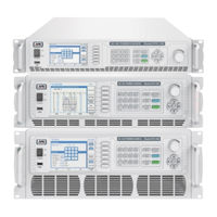
Manuals and User Guides for APS CPS130. We have
1
APS CPS130 manual available for free PDF download: Operation Manual
APS CPS130 Operation Manual (231 pages)
Programmable AC & DC Power Supplies
Brand:
APS
| Category:
Power Supply
| Size: 8 MB
Table of Contents
Table of Contents
3
1 Contact Information
11
2 Warranty, Service and Safety Information
12
Limited Warranty
12
Service and Spare Parts Limited Warranty
12
Safety Information
12
Safety Notices
14
3 Product Overview
16
General Description
16
Models CPS106, CPS110 & CPS115
16
Model CPS120
17
Models CPS130, CPS140 & CPS150
17
Product Features
18
Standard Versus Enhanced Versions
18
Output Voltage Coupling Modes
19
Voltage Ranges
19
Table 3-1: CPS100 Series Output Coupling Modes
19
Table 3-2: Available Voltage Ranges by Output Mode
19
Current Protection Modes
20
Voltage & Current Output Profiles
20
CPS106 Model VI Curves - 600W
21
Figure 3-1: CPS106 Model VI Curves
21
CPS110 Model VI Curves - 1000W
22
Figure 3-2: CPS110 Model VI Curves
22
CPS115 Model VI Curves - 1500W
23
Figure 3-3: CPS115 Model VI Curves
23
CPS120 Model VI Curves - 2000W
24
Figure 3-4: CPS120-Model VI Curves
24
CPS130 Model VI Curves - 3000W
25
Figure 3-5: CPS130-Model VI Curves
25
CPS140 Model VI Curves - 4000W
26
Figure 3-6: CPS140-Model VI Curves
26
CPS150 Model VI Curves - 5000W
27
Figure 3-7: CPS150-Model VI Curves
27
4 Technical Specifications
28
Output
28
Metering
29
System Parameters, Protections & Control Interfaces
31
AC Input
31
Programmable Functions
32
Test Functions
32
Dimensions & Weight
32
Dimensions 2U Models CPS106, CPS110, CPS115
33
Figure 4-1: Dimension Drawing 2U Models
33
4.7.1 Dimensions 3U Model CPS120
34
Figure 4-2: Dimension Drawing 3U Model
34
4.7.1 Dimensions 4U Models CPS130, CPS140, CPS150
35
Figure 4-3: Dimension Drawing 4U Models
35
Environmental
36
Safety & Regulatory
36
ENHANCED Versions - Additional Specifications
37
Remote Control Interfaces
37
4.11.1 RS232 Interface
37
4.11.2 RS485 Interface
38
4.11.3 USB Interface
38
LAN Interface (Option on 2U Models)
38
GPIB Interface (Option)
39
Options for CPS106, CPS110, CPS115
39
Options for CPS120, CPS130, CPS140, CPS150
39
5 Unpacking and Installation
40
Inspection
40
Proper Lifting and Handling Guidelines
40
Figure 5-1: Model 5L18-36 VI Curve
40
Unpacking CPS106, CPS110, CPS115 and CPS120 Models
41
Figure 5-2: Lifting Do's and Don'ts Chart
41
Unpacking CPS130, CPS140 and CPS150 Models
42
Ship Kits
44
CPS Series Ship Kit Contents
44
Figure 5-3: CPS100 Series Ship Kit Content
44
Table 5-1: CPS Series Included Accessories Ship Kit
44
AC Input Connections
45
AC Input Wire Sizes by Model
46
AC Input Terminal as Safety Cover
46
Table 5-2: AC Input Wire Sizes by Model
46
Input Power Cord Installation
47
Grounding Requirements
47
Check Line Voltage
48
Cleaning
48
Powering up
48
In Case of Malfunction
48
Output Terminals
49
Rear Panel Models CPS106, CPS110, CPS115
49
Rear Panel Model CPS120
49
Figure 5-4: Output Terminal Locations - 2U Models
49
Figure 5-5: Output Terminal Locations - 3U Models
49
Rear Panel Models CPS130, CPS140, CPS150
50
Figure 5-6: Output Terminal Locations - 4U Models
50
Output Terminal Connections
51
Recommended Output Wire Size
51
Table 5-3: Recommend Output Wire Sizes by Model
51
Output Power Cord Connection
52
Connecting a UUT
52
Remote Voltage Sense
53
Figure 5-7: Voltage Sense Connections
53
Rear Panel Controls and Connectors
54
CPS106, CPS110, CPS115 Rear Panel Overview
54
CPS120 Rear Panel Overview
54
Figure 5-8: Rear Panel Callouts - 2U Models
54
Figure 5-9: Rear Panel Callouts - 3U Model
54
CPS130, CPS140, CPS150 Rear Panel Overview
55
Figure 5-10: Rear Panel Callouts - 4U Models
55
AUX I/O Card Connectors (CPS120 ~ CPS150 Models)
56
EXT I/O Card Connectors (CPS106, CPS110 & CPS115 Models)
56
Figure 5-11: AUX I/O Option Card Connections
56
AUX I/O Card Pin Assignments
57
Table 5-4: AUX I/O Analog Pin Functions
57
Table 5-5: AUX I/O Digital Input Pin Functions
57
Remote Control Programming Interfaces
58
5.10.1 RS232 Serial Interface
58
Table 5-6: RS232 DB9 Pin Assignments
58
Figure 5-12: CPS106, CPS110 or CPS115 Rear Panel with Optional LAN+GPIB Interfaces
58
Figure 5-13: RS232 Connector
58
5.10.2 RS485 Serial Interface
59
5.10.3 USB Interface
60
LAN Interface (Option on CPS106, CPS110 & CPS115)
60
GPIB Interface (Option on All CPS Models)
61
5.10.6 Remote Control Commands
62
Table 5-7: IEEE-488 Connector Pin Assignments
62
Figure 5-14: Interface Installation on 2U Models
63
Figure 5-15: Interface Installation on 3U and 4U Models
63
Installation of Optional Remote Control Interfaces
63
Instrument Rack Installation
64
Installing Rack Mount Handles
64
Rack Installation
65
Figure 5-16: Cabinet Installation Drawing
65
6 Front Panel Operation
66
Powering on
66
Figure 6-1: Power-On Diagnostics Screen
66
Operating Modes
67
Front Panel Layout
68
Figure 6-2: CPS100 Series Front Panel Displays and Controls
68
Front Panel Controls
69
LCD Touch Screen
69
Soft Keys
70
Decimal Keypad
70
Multi-Function Keys
70
ADJUST Shuttle Knob
71
Cursor Keys
71
Menu Structure
71
Table 6-1: Cursor Keypad Functions
71
Figure 6-3: Complete Menu Structure Overview
72
MAIN Screen
73
SETTING Screens
74
Figure 6-4: SETTING Menu Structure
74
Output & more Settings
75
Measurement Settings
80
Table 6-2: Available Measurements and Units
81
Waveform Viewer
83
Limitation (User Limits)
83
MENU Screens
84
Figure 6-5: Menu Structure
84
Config
85
Table 6-3: Configurable Protection Modes
94
LCD Setting
95
Calibration
96
Master/Slave
96
Other
97
OUTPUT MODE Screens
98
Figure 6-6: Output Mode Menu Structure
98
Power Line Distortion Testing (PLD)
99
Figure 6-7: Illustration of a LIST Transient
99
Figure 6-8: Illustration of a PULE Transient
102
Figure 6-9: Illustration of a STEP Transient
104
Harmonics
106
IEC Standards
113
Table 6-4: IEC 61000-4 Test Standards Supported on Enhanced Models
113
Figure 6-10: IEC 6100-4-11 Standard Voltage Variation
118
Figure 6-11: IEC 61000-4-13 Flat Curve
120
Figure 6-12: IEC 61000-4-13 over Swing
120
Figure 6-13: IEC 4-28 Frequency Variation Sequence
138
Figure 6-14: IEC 4-28 Frequency Transition Time Tp
139
Special Functions
141
Table 6-5: Transient Function Specifications
142
Test Mode
145
PARALLEL / SERIES / 3-PHASE Screen
147
STORE / RECALL Screens
148
Figure 6-15: STORE / RECALL Menu Structure
148
LOCK Screen
150
7 Remote Control Programming
151
Overview
151
Command Syntax
151
Command Terminators
151
Numeric Parameters
151
Parameter Unit Options
151
Syntax Notation Convention
152
IEEE488.2 Common Commands
152
Table 7-1: IEEE488.2 Common Commands Supported
152
Measurement Commands
153
Table 7-2: Measurement Commands
153
Harmonics Measurement Commands
154
Table 7-3: Measurement Commands
154
Status Commands
155
Table 7-4: Status Commands
155
Table 7-5: Error Codes - Stand-Alone Mode
155
Table 7-6: Error Codes -Master / Slave Mode
155
Programming Commands
156
OUTPUT Sub-System
156
Table 7-7: OUTPUT Sub-System Commands
158
LIMIT Sub-System
159
Table 7-8: LIMIT Sub-System Commands
159
7.8.1 CCMODE Sub-System
160
7.8.2 LIST Sub-System
160
Table 7-9: CCMODE Sub-System Commands
160
Table 7-10: LIST Sub-System Commands
163
Figure 7-1: Transient Front Panel Vs Commands Relationship
163
7.8.3 PULSE Sub-System
166
Table 7-11: PULSE Sub-System Commands
166
7.8.4 STEP Sub-System
167
Table 7-12: STEP Sub-System Commands
167
Synthesis Commands
168
System Commands
169
Table 7-13: Waveform Synthesis System Commands
169
Table 7-14: System Commands
169
External Input Control Mode Commands
170
Table 7-15: External Input Commands
170
Master / Slave Configuration Commands
171
Master / Slave Programming Commands
171
Master / Slave Measurement Commands
171
Table 7-16: Master / Slave Programming Commands
171
Table 7-17: Master / Slave Configuration Commands
172
8 Master Slave Operation
174
Overview
174
Restrictions
174
Figure 8-1: Measurement Readings Wye Configurations Versus Delta Configuration
181
Table 8-1: Multi-Unit Programming Summary
187
Figure 9-1: Device Driver, Other Devices, USB Entry
189
Table 11-1: Required Calibration Equipment List
206
Table 13-1: Troubleshooting Matrix
227
Advertisement
Advertisement
Related Products
APS CPS100 Series
APS CPS106
APS CPS110
APS CPS115
APS CPS120
APS CPS140
APS CPS150
APS CFS108
APS CFS116
APS CFS300 Series
APS Categories
Automobile Accessories
Measuring Instruments
Inverter
Power Supply
Media Converter
More APS Manuals
Login
Sign In
OR
Sign in with Facebook
Sign in with Google
Upload manual
Upload from disk
Upload from URL