Sign In
Upload
Manuals
Brands
APS Manuals
Power Supply
CFS108
APS CFS108 Manuals
Manuals and User Guides for APS CFS108. We have
1
APS CFS108 manual available for free PDF download: Operation Manual
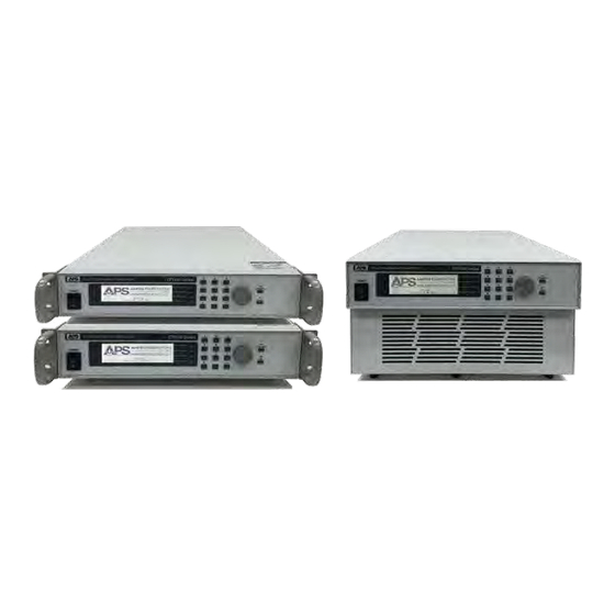
APS CFS108 Operation Manual (146 pages)
CFS100 Series. Programmable AC & DC Power Supply
Brand:
APS
| Category:
Power Supply
| Size: 5 MB
Table of Contents
Table of Contents
3
1 Contact Information
9
2 Front Matter
10
Limited Warranty
10
Service and Spare Parts Limited Warranty
10
Safety Information
10
Safety Notices
12
3 Product Overview
14
General Description
14
Model CFS108
14
Model CFS116
14
Model CFS140
15
Product Features
15
Operating Modes
16
Voltage Programming
17
Minimum Voltage
17
Voltage Range AUTO Mode
17
Table 3-1: Available Voltage Ranges by Output Mode
17
Current Protection Modes
18
Voltage & Current Output Profiles
19
CFS108 AC Mode VI Curve
20
Figure 3-1:CFS108-AC-Vi_Curve-150V_Range
20
Figure 3-2: CFS108-AC-Vi_Curve-300V_Range
20
CFS108 DC Mode VI Curve
21
Figure 3-3:CFS108-DC-Vi_Curve-200V_Range
21
Figure 3-4: CFS108-DC-Vi_Curve-400V_Range
21
CFS116 AC Mode VI Curve
22
Figure 3-5:CFS116-AC-Vi_Curve-150V_Range
22
Figure 3-6: CFS116-AC-Vi_Curve-300V_Range
22
CFS116 DC Mode VI Curve
23
Figure 3-7:CFS116-DC-Vi_Curve-200V_Range
23
Figure 3-8: CFS116-DC-Vi_Curve-400V_Range
23
CFS140 AC Mode VI Curve
24
Figure 3-9:CFS140-AC-Vi_Curve-150V_Range
24
Figure 3-10: CFS140-AC-Vi_Curve-300V_Range
24
CFS140 DC Mode VI Curve
25
Figure 3-11:CFS140-DC-Vi_Curve-200V_Range
25
Figure 3-12: CFS140-DC-Vi_Curve-400V_Range
25
4 Technical Specifications
26
AC Output
26
DC Output
27
Power Connections
27
Metering - AC Mode
28
Metering - DC Mode
29
Protection Modes
29
AC Input
30
AC Input Current Vs AC Output Current - Model CFS108
30
Figure 4-1: AC Input Current Vs AC Output Current - Model CFS108
30
AC Input Current Vs AC Output Current - Model CFS116
31
AC Input Current Vs AC Output Current - Model CFS140
31
Figure 4-2: AC Input Current Vs AC Output Current - Model CFS116
31
Figure 4-3: AC Input Current Vs AC Output Current - Model CFS140
31
System Parameters
32
Test Mode Parameters
32
Interface and I/O
33
Dimensions & Weight
33
Environmental
33
Safety & Regulatory
33
5 Unpacking and Installation
34
Inspection
34
Proper Lifting and Handling Guidelines
34
Figure 4-1: Model 5L18-36 VI Curve
34
Figure 5-2: Lifting Do's and Don'ts Chart
35
Unpacking CFS108 and CFS116 Models
35
Unpacking CFS140 Models
36
Ship Kits
38
CFS108 Ship Kit Contents
38
Table 5-1: CFS108 Included Accessories Ship Kit
38
Figure 5-3: CFS108 Ship Kit Content
38
CFS116 Ship Kit Contents
39
Table 5-2: Cfs116Included Accessories Ship Kit
39
Figure 5-4: CFS116 Ship Kit Content
39
CFS140 Ship Kit Contents
40
Table 5-3: CFS140 Included Accessories Ship Kit
40
Figure 5-5: CFS140 Ship Kit Content
40
AC Input Connections
41
Grounding Requirements
41
Check Line Voltage
42
US Line Cord Requirements
42
European Line Cord Requirements
42
CFS108 Models
43
CFS116 & CFS140 Models
43
Table 5-4: AC Input Voltage Identification Location CFS116
43
Figure 5-6: AC Input Voltage Selector Switch Location CFS108
43
CFS140 AC Input Fuses & Circuit Breaker
44
Cleaning
44
Figure 5-7: CFS140 AC Input Circuit Breaker Location
44
Powering up
45
In Case of Malfunction
45
Output Terminals
46
Model CFS108 Output Terminal Location
46
Model CFS116 Output Terminal Location
46
Figure 5-8: CFS108 Output Terminals
46
Figure 5-9: CFS116 Output Terminals
46
Model CFS140 Output Terminal Location
47
Figure 5-10: CFS140 Output Terminals
47
Recommended Output Wire Size
48
Connecting a UUT
48
Table 5-5: Recommend Output Wire Sizes by Model
48
Rear Panel Controls and Connectors
49
CFS108 Rear Panel Overview
49
Figure 5-11: CFS108 Rear Panel Callouts
49
CFS116 Rear Panel Overview
50
Table 5-6: CFS108 Rear Panel Callouts
50
Table 5-7: CFS116 Rear Panel Callouts
50
Figure 5-12: CFS116 Rear Panel Callouts
50
CFS140 Rear Panel Overview
51
Table 5-8: CFS140 Rear Panel Callouts
51
Figure 5-13: CFS140 Rear Panel Callouts
51
REMOTE OUTPUT Connecter
52
Table 5-9: REMOTE OUTPUT CONNECTOR Pins
52
Remote Control Programming Interfaces
53
RS232 Serial Interface
53
Table 5-10: RS232 DB9 Pin Assignments
53
Table 5-11: Serial Cable to PC COM Port
53
Figure 5-14: RS232 Connector
53
USB Interface
54
LAN Interface (Option)
54
GPIB Interface (Special Order)
54
Figure 5-15: LAN Option Connectors
54
Figure 5-16: Effect of Current Slew Rate Settings on Power Supply Testing
54
Control Commands
55
Table 5-12: IEEE-488 Connector Pin Assignments
55
Sending Commands over RS232 / USB or LAN
56
Receiving Commands over RS232 / USB or LAN
56
6 Front Panel Operation
57
Powering on
57
Front Panel Layout
57
Figure 6-1: CFS100 Series Front Panel Displays and Controls
57
LED Status Indications
59
Shuttle Knob
59
Table 6-1: Front Panel Status LED Indications
59
Setup Screen Readouts
60
Table 6-2: Setup (Set) Screen Display Fields Description
60
Main Menu Soft Keys
61
Table 6-3: Available Top Level Menus
61
Lower Level Menu Soft Keys
62
Table 6-4: Available Soft Key Labels
62
Password Protection
63
Password Assignment or Change
63
Forgotten Password
63
Operating Mode - Selecting
64
Available Operating Modes
64
On Screen Operating Mode Indication
64
Figure 6-2: PROGRAM MODE LCD Indicator
64
Figure 6-3: MANUAL MODE LCD Indicator
65
Figure 6-4: DC MODE LCD Indicator
65
PROGRAM Mode Operation
66
PROGRAM Mode System Settings
66
Auto Run Mode Selections
67
Single Step Modes
67
Alarm Settings
68
LCD Contrast
68
Power-Up Settings
69
Loop Cycle Settings
70
Results Display Mode Settings
70
Over Current Fold Mode Settings
71
Keyboard Lock Mode Settings
71
Memory Lock Mode Settings
72
PROGRAM MODE - Using Memories and Steps
73
Selecting a Memory Location
73
Assigning a Name to a Memory Location
74
Selecting a Program Step
75
Program Step Parameters Available
76
Editing Step Parameters
78
Table 6-5: PROGRAM Mode Step Parameters Available
78
PROGRAM Mode - Step Parameter Details
79
Phase Angles
79
Memory Cycles
80
Voltage Programming
80
Frequency Programming
81
Measurement Limits Programming
82
Time Duration Programming
83
Table 6-6: Programmable Step Time Parameters
83
Figure 6-5: Step Time Parameters Relationship
83
Surge/Drop Programming
84
Table 6-7: Programmed Voltage Drop Example Settings
85
Figure 6-6: Programmed Voltage Drop Example Waveform
86
User Prompt Programming
87
Step Cycle Programming
88
Connect Mode Programming
88
Reviewing Test Results
89
PROGRAM Mode Execution
90
Initiating a Test
90
Monitoring Test Execution
90
Cycle Display Mode
91
Operator Interruption and Voltage Adjust
91
Triggering a Voltage Surge/Sag
92
End of Test Status
93
MANUAL (AC) Mode Operation
94
Available Parameters in MANUAL Mode
94
Programming MANUAL Mode Parameters
94
MANUAL (AC) Mode Execution
95
DC Mode Operation
97
Available Parameters in DC Mode
97
Programming DC Mode Parameters
97
DC Mode Execution
98
7 Remote Control Programming
99
Overview
99
Command Syntax
99
Command Terminators
99
Numeric Parameters
99
Parameter Unit Options
99
Syntax Notation Convention
100
Test Control Command and Query Syntax
101
Table 7-1: Test Control Command and Query Summary
101
Parameter Setup Command and Query Syntax
104
System Command and Query Syntax
106
Table 7-2: Parameter Setup Command and Query Summary
106
IEEE488.2 Common Commands
108
Command Commands Summary Table
108
Idn
109
Rst
109
Tst
109
Cls
109
Opc / *Opc
109
Wai
109
Table 7-3: IEEE488.2 Common Commands Supported
109
Esr
110
ESE <Value> / *ESE
110
Stb
110
SRE <Value> / *SRE
110
Psc {1|0} / *Psc
110
8 USB Driver Installation
111
Overview
111
9 LAN Interface Configuration
116
Overview
116
Collect Network Information
116
Saving LAN Settings
116
Figure 9-1: Network Information Required for LAN Setup
116
LAN Option Setup Menu
118
IP Setup Mode
118
Manual IP Address Setting
119
Gateway Address Setting
119
Subnet Mask Setting
120
Device Name Setting
120
MAC Address
121
Establishing LAN Connection Using ni MAX Explorer
122
Power Source
123
LAN Interface Specific Commands and Queries
131
Communication Considerations
131
Table 9-1: LAN Option Interface Specific Commands
131
Ethernet Setting Commands Wait Times
132
Table 9-2: LAN Option Interface Command Wait Times
132
10 Calibration
133
Overview
133
Hardware Verification Procedure
133
Required Calibration Instruments and Standards
133
Hardware Verification Procedure Steps
133
Figure 10-1: DC Offset Measurement
134
Hardware Calibration Procedure
135
Required Calibration Instruments and Standards
135
Figure 10-2: DC Offset Measurement
136
Software Calibration Procedure
138
Required Calibration Instruments and Standards
138
Voltage: 150.0V Calibration
139
Voltage: 300.0V Calibration
140
High & Low Current Range Calibration
140
High & Low Power Range Calibration
141
Peak Current Calibration
142
Exiting Calibration Mode
142
11 CE MARK Declaration of Conformity
143
Index
144
Advertisement
Advertisement
Related Products
APS CFS116
APS CFS140
APS CFS300 Series
APS CPS106
APS CPS110
APS CPS115
APS CPS120
APS CPS130
APS CPS140
APS CPS150
APS Categories
Automobile Accessories
Measuring Instruments
Inverter
Power Supply
Media Converter
More APS Manuals
Login
Sign In
OR
Sign in with Facebook
Sign in with Google
Upload manual
Upload from disk
Upload from URL