Sign In
Upload
Manuals
Brands
Applanix Manuals
Control Unit
POS AVX 210
Applanix POS AVX 210 GNSS Solution Manuals
Manuals and User Guides for Applanix POS AVX 210 GNSS Solution. We have
1
Applanix POS AVX 210 GNSS Solution manual available for free PDF download: User Manual
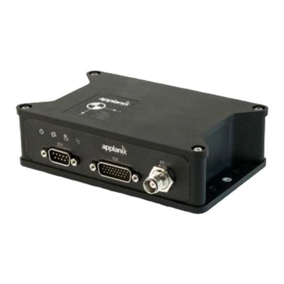
Applanix POS AVX 210 User Manual (51 pages)
Brand:
Applanix
| Category:
Control Unit
| Size: 2 MB
Table of Contents
Table of Contents
2
1 Introduction
6
POS AVX 210 Specification
6
2 POS AVX 210 Features
6
Figure 1: POS AVX210 Enclosure
6
3 POS AVX 210 Hardware Description and Interface
7
Mechanical
7
Figure 2: POS AVX210 Mechanical Drawing
8
Electrical
9
Figure 3: POS AVX 210 Center of Navigation
9
Antenna
10
Figure 4: Trimble AV39 GNSS Antenna
10
Power / IO Connector
10
Figure 5: Power / IO Connector Pin-Out
11
Figure 6: I/O Cable P/N 10006215
13
I/O Cable
13
Figure 7: Cable Wiring Diagram
14
Figure 8: Trimble Storage over USB
14
LED Functionality
15
4 POS AVX 210 Control Software and Configuration
15
Connecting a Web Browser
15
Figure 9: POS AVX 210 LED Functionality
15
Figure 10: Connection Credentials
16
Figure 11: Welcome Screen
16
Web User Interface Layout
17
Figure 12: Language Selection
17
Figure 13: Main Menu
17
Receiver Status, Solution Monitor and Display
18
Data Logging
18
Figure 14: System Status- Identity
18
Figure 15: Data Logging Start/Stop
19
Figure 16: Logging Configuration
20
PPS and ASCII Time Tag Synchronization
21
PPS Signal
21
Figure 17: Data Files
21
PPS ASCII Time Tag Message
22
Figure 18:PPS Time Tag
22
System Configuration
23
Antenna Configuration
23
Figure 19: Receiver Configuration
23
Figure 20: Antenna Configuration
23
Tracking Configuration
24
Figure 21: Tracking Configuration
24
Position Configuration
25
Figure 22: Position Configuration
25
General Configuration
26
Figure 23: Receiver Reset
26
Figure 24: General Configuration
26
INS Configuration
27
Figure 25: IMU Body Frame Definition
28
Figure 26: Vehicle Body Frame
29
Figure 27: POS AVX 210 Reference and IMU Body Frame
31
Figure 28: ins Configuration
32
I/O Configuration
33
Figure 29: I/O Configuration
33
Differential Corrections Configuration
34
Figure 30: Message Selection
34
Ethernet Configuration
35
Firmware Upgrade
35
Figure 31: Differential Solution Display
35
Figure 32: Ethernet Configuration
35
5 Real Time Output ICD
36
ASCII-NMEA Output
36
Figure 33: Firmware Installation
36
Figure 34: ASCII Message Selection
37
Nonstandard ASCII Messages
37
Binary Output
39
Binary Data Types
39
Binary Output ICD
40
Figure 35: Binary Message Selection
40
GSOF 49 (31H) ins Integrated Navigation Solution
42
GSOF 50 (32H) ins Integrated Navigation Solution RMS
44
GSOF 51 (33H) Event Marker Information
46
6 Flight Management System Support
47
7 Integration Examples and Notes
47
Phaseone IXU Camera Integration
47
Figure 36:Nanotrack
47
Figure 37: Phaseone-POS AVX210 -Nanotrack Components
48
Figure 38: Connection Diagram
49
Figure 39: AV39 Configuration
50
Figure 40: Autolog Setup
50
8 Technical Support
51
Advertisement
Advertisement
Related Products
Applanix APX-18
Applanix POS MV V5
Applanix POS MV V5-1
Applanix POS MV V5-2
Applanix POS MV V4
Applanix POS MV V4-1
Applanix POS MV 320
Applanix POS MV WaveMaster
Applanix POS MV WaveMaster RM
Applanix Categories
Marine Equipment
Control Unit
Car Navigation system
Receiver
Antenna
More Applanix Manuals
Login
Sign In
OR
Sign in with Facebook
Sign in with Google
Upload manual
Upload from disk
Upload from URL