Sign In
Upload
Manuals
Brands
APP Manuals
Measuring Instruments
APP-601
User Manuals: APP APP-601 Measuring Instruments
Manuals and User Guides for APP APP-601 Measuring Instruments. We have
1
APP APP-601 Measuring Instruments manual available for free PDF download: Operating Manual
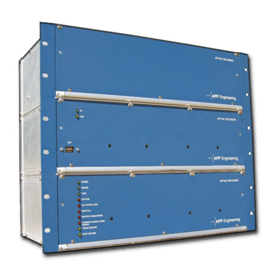
APP APP-601 Operating Manual (146 pages)
Brand:
APP
| Category:
Measuring Instruments
| Size: 4 MB
Table of Contents
Table of Contents
7
Table of Figures
12
1 Introduction
15
Overview
16
History
16
Features
16
Functions
17
2 Specifications
18
Analog Inputs
19
Voltage
19
Current
19
General
19
Event Inputs
20
Power Supply
20
Status Relays
21
Time Synchronization
21
Communications
22
System Computer
22
Choice #1 APP-601 Computer Chassis
22
Choice #2 APP-501 Computer Chassis
23
Ethernet Switch
24
Enclosures
24
Environment
24
Approvals
24
3 Installation Overview
25
Installation Types
26
Completing a Centralized Installation
27
Figure 1: APP-601 Computer Control Chassis Front View (Fanless)
27
Figure 2: APP-501 Computer Control Chassis Front View
27
Figure 3: Data Chassis Front View
27
Completing a Distributed Installation
31
Completing a Turn-Key Installation
34
Basic Connection Diagram
36
Figure 4: Chassis Interconnection Diagram (Reference) (with APP-501 Computer Control Chassis)
36
Figure 5: Chassis Interconnection Diagram (Reference) (with APP-601 Computer Control Chassis)
37
4 Hardware
38
Available Computer Control Chassis
39
Major Duties of the Computer Control Chassis
39
Computer Control Chassis
39
Important APP-601 Computer Circuit Board Connector Points
41
Table 1: APP-601 Computer Circuit Board Connector Points
41
Computer Control Chassis Specifications
42
Table 2: APP-601 Computer Control Chassis Specifications
42
Figure 6: APP-601 Computer Control Chassis Front View
43
Figure 7: APP-601 Computer Control Chassis Rear View
43
Computer Control Chassis
44
Computer Control Chassis Specifications
45
Figure 8: APP-501 Computer Control Chassis 3D View
45
Table 3: 501 Computer Control Chassis Specifications
45
Figure 9: APP-501 Computer Control Chassis Front View
46
Figure 10: APP-501 Computer Control Chassis Rear View
46
Data Chassis
47
Power Supply Circuit Board
47
5VDC Power Supply Module
48
Alarm Circuit Board
49
Figure 11: Cross Trigger over IP Network
51
Event Circuit Board
52
Figure 12: Cross Trigger Wiring, 3 DFR Example
52
DSP/IRIG Circuit Board
53
Table 4: Syncmethod and Corresponding Hardware 3-PIN Jumper Position
53
Analog Circuit Board
55
Front Panel Led's
55
Table 5: Description of Leds
55
Figure 13: APP-601 Data Chassis 3D View
56
Figure 14: APP-601 Data Chassis Front View
57
Figure 15: APP-601 Data Chassis Rear View
57
Ethernet Switch
58
Table 6: Switch Specifications
58
Table 7: Pin out
59
Networking
60
Table 8: Ethernet and IP Addresses for the DSP Network
60
5 Installing the Recorder Software
61
Introduction
62
Program Installation and Quick Start Settings
62
Figure 16: Recorder Configuration Window
63
Figure 17: Point Assignment Window's Chassis Configuration
64
Startup and Running the APP Monitor
65
Figure 18: Point Assignment Window: General Settings Tab
65
Figure 19: Windows Logon & Setup Window
66
6 Using the APP Recorder
67
Introduction
68
APP Recorder Program Functions
68
The APP Recorder Program Main Window
68
Figure 20: APP Recorder Program Main Window
69
Figure 21: Analog Tab
69
Figure 22: Triggers Tab
70
Figure 23: Events/Ser Tab
70
Figure 24: SER Report Tab
70
Setting the Administrator Password
71
Figure 25: Fault Location Tab
71
Table 9: Values on the SER Report Tab
71
Printing
72
Selecting and Configuring the Printer
72
Printing the Contents of the Message Window
72
Printing the Recent Fault Summary
72
Printing the Recent Fault Summary with a Graph
73
Exiting the APP Recorder
73
Configuring the APP Recorder
74
Factory Settings
74
Types of Configuration Settings
74
Configuring the Main Configuration Settings
74
Figure 26: Example of APP 601 Recorder Configuration Window-Main Tab
75
Setting up Dial-Up Networking
77
Configuring Automatic Tasks
78
Accessing the Automatic Tasks Tab
79
Configuring Automatic Tasks that Occur When a Fault Arrives
79
Figure 27: Recorder Configuration Window -Automatic Tasks Tab
79
Table 10: Configuring Automatic Tasks-Options in the Call Master List
80
Configuring Printing
81
Table 11: Configuring Automatic Tasks-Options in the Print List
82
Configuring the Format of Printed Reports
83
Figure 28: Printing Format Window
83
Figure 29: Default Report Format
85
Figure 30: Report with Spread Digital Among Graphs Checked
85
Configuring Email Settings
86
Figure 31: Auto Email Setup Window
87
Figure 32: Manual Emailing Window
88
Configuring FTP Settings
89
Figure 33: FTP Account Settings Window
89
Figure 34: FTP Remote Directory Setup Window
91
Defining a Boolean Logic Equation
92
Performing a Test Upload
92
Table 12: Defining a Boolean Logic Filter-Variables and Entries
92
Configuring Automatic SER Reports
93
Figure 35: FTP Upload or Testing Window
93
Calling the Master Phone List When Alarms Occur
94
Configuring the Master Phone List
94
Figure 36: Master Phone & Network List Window
95
Ping Master Every 5 Minutes
96
Configuring Allowed Ips
96
Figure 37: Allowable Ips Entry Window (Security Feature)
96
Printing Recorder Configuration
97
Editing the Point Assignment Record
97
Editing the Line Group Record
97
Connecting to Clearview
98
Disconnecting from Clearview
98
Viewing the Connection Status Window
98
Figure 38: Connection Status Screen
98
Choosing a Modem
99
Setting the Network Port Number
99
Figure 39: Choose Modem Window
99
Turning on or off Dial-Up Networking
100
Maintaining the APP Recorder
100
Viewing Trace Files
100
Running a Diagnostic Test and Viewing Results
101
Figure 40: Recorder Diagnostic Results Window
101
Viewing All SER Abnormal or Stopped Channels
102
Performing a Test Run
102
Figure 41: Stopped/Abnormal SER Channels Window
102
Viewing the on Alarms
103
Resetting FID
103
Figure 42: Alarms Currently on Window
103
Re-Initializing the APP Recorder Program
104
Restart Recorder
104
Rebooting the APP Recorder Program
104
Reserving Memory and Defragging the Data Drive
105
Continuous Recording
106
Viewing the Continuous Recording Status Window
106
Figure 43: Continuous Recording Menu
106
Saving Oscillograph Data
107
Figure 44: Continuous Recording Status Window
107
Figure 45: Time Slice Entry Window
107
Saving Frequency Data
108
Figure 46: Save Freq Data File
108
Saving RMS Data
109
Saving Phase Data
109
Saving RMS-Plus Phase Data
109
Using Other Tools
110
Startup and Running the APP Monitor
110
Figure 47: Tools Menu Window
110
Figure 48: Windows Logon & Startup
110
Network Path Logon
111
Figure 49: Network Path Logon
111
Configuring a Dnp3/Modbus Outstation
112
Figure 50: DNP-3/Modbus Configuration Window (DNP-3)
112
Table 13: DNP-3 Objects and Variations
113
To Configure a Dnp3/Modbus Outstation Point Mapping TAB
114
Figure 51: DNP-3/Modbus Configuration Window (Modbus)
114
Table 14: Modbus Function Codes
114
Figure 52: Point Mapping
115
Emailing a Fault Summary Record
116
Showing the Email Settings Window
116
FTP a Fault File
116
Show FTP Window
116
Figure 53: DNP-3/Modbus Status Window
116
Configuring a DSP Board's Ethernet and IP Address Settings
118
Configuring a Phasor Measurement Unit (PMU)
119
Figure 54: DSP Board Setup Window
119
Figure 55: PMU Window
120
Figure 56: PMU - Sending Format
122
Viewing the Help and about Information
123
7 Using the APP Driver
124
Introduction to the APP Driver
125
Viewing the APP Recorder Driver Window
125
Figure 57: the APP Recorder Driver Window
125
Reinitializing the APP Driver
126
Exiting the APP Driver
126
Doing a Diagnosis
126
Performing a Test Run from the APP Driver
126
Pmu
126
Viewing the Help and about Information
127
8 Using the Oscope
128
Introduction to the Oscope
129
Viewing the Oscope (Oscilloscope) Window
129
Analog Tab
129
Figure 58: Oscope Window, Analog Tab
129
Events Tab
130
Triggers Tab
130
Figure 59: Oscope Window, Event Status Tab
130
Figure 60: Oscope Window, Analog Trigger Status Tab
130
Yscale Controls
131
Meter Controls
131
Analog Channel Controls
131
Run Controls
131
Table 15: Oscope Window-Y Scale Options
131
Bottom Tray
132
Reinitializing the Oscope Window
132
Exiting the Oscope Window
132
Editing the Point Assignment Record
132
Viewing Driver Status
132
Figure 61: DSP Board Communication Status Window
133
Table 16: DSP Board Communication Status Window-Fields
133
Viewing Stopped/Abnormal SER Channels
134
Advanced Menu
134
Calibrating and Un-Calibrating All Offsets
134
Figure 62: Stopped/Abnormal SER Channels Screen
134
Table 17: SER Report Tab-Letter Values
134
Setting All Analog Channel Inputs to Zero
135
Turning on All Alarms and Leds
135
Rebooting the Driver
136
Calibrating and Un-Calibrating One Channel at a Time
136
Calibrating the DC Offset One Channel at a Time
136
Calibrating and Un-Calibrating Offsets One Channel at a Time
137
Calibrating Slope (Performing an External Calibration)
137
Figure 63: Show Analog Channels Group
137
Figure 64: Calibrate/Un-Calibrate Offset
137
Figure 65: External Calibration (Slope) Group
138
9 Other Information
139
Time Quality
140
Table 18: IEEE 1344 Time Quality Values
140
Recommended Maintenance and Calibration
141
Performance-Based Maintenance
141
Table 19: Time Quality and APP-601 Action
141
Time-Based Maintenance
142
Recommended Setup for MW Channels (Using 4Ma-20Ma Transducer)
142
Table 20: Time-Based Maintenance Procedures
142
Recommended Setup for MVAR Channels (Using 4Ma-12Ma-20Ma Transducer)
143
Recommended Setup for a Current Channel Using a 4Ma-20Ma Transducer (E.g. Measuring Generator Field Current)
144
Linux Ubuntu Operating System
145
Viewing Screens
145
Figure 66: Linux Ubuntu os and Virtual Machine Diagram
145
Stopping the APP Recorder Program
146
Shutting down the Computer Chassis
146
Other Information
146
Advertisement
Advertisement
Related Products
APP Categories
Cables and connectors
Crimp tool
Amplifier
Racks & Stands
Controller
More APP Manuals
Login
Sign In
OR
Sign in with Facebook
Sign in with Google
Upload manual
Upload from disk
Upload from URL