Table of Contents
Advertisement
Quick Links
Advertisement
Table of Contents

Summary of Contents for APP APP-601
- Page 1 APP-601 Recorder Operating Manual...
- Page 2 APP Engineering, Inc. shall not be liable for errors or for incidental or consequential damages in connection with the furnishing, use, or performance of this document or any information contained herein.
- Page 3 (60) days from the date of delivery of the Software to you. Your sole remedy in the event of a breach of this warranty will be that APP Engineering, Inc. will, at its option, replace any defective media returned to APP Engineering, Inc.
- Page 4 Engineering, Inc. be liable to the purchaser for any special, consequential, indirect or similar damages, including any lost profits or lost data arising out of the use or inability to use the software even if APP Engineering, Inc. has been advised of the possibility of such damages. Some states do not allow the limitation of exclusion of liability for incidental or consequential damages so the above limitation or exclusion may not apply to you.
- Page 5 Safety Notices Do not install substitute parts or perform any unauthorized modification to the product. Return the product to APP Engineering, Inc. for service and repair to ensure that safety features are maintained. *WARNING* A WARNING notice denotes a hazard. It calls attention to an operating procedure, practice, or the like, that if not correctly performed or adhered to, could result in personal injury or death.
- Page 6 Additional Document Notes Throughout this manual, the APP-601 Recorder™ may be referred to as the “Recorder” or the APP-601 Multifunction Recorder. Throughout this manual an event channel or event input may be referred to as a digital channel or digital...
-
Page 7: Table Of Contents
Power Supply ..........................2-3 Status Relays ..........................2-4 Time Synchronization ........................2-4 Communications ........................... 2-5 System Computer .......................... 2-5 2.7.1 Choice #1 APP-601 Computer Chassis ................2-5 2.7.2 Choice #2 APP-501 Computer Chassis ................2-6 Ethernet Switch ..........................2-7 Enclosures ............................. 2-7 2.10 Environment .......................... - Page 8 4.3.1 Important APP-601 Computer Circuit Board Connector Points .......... 4-4 4.3.2 APP-601 Computer Control Chassis Specifications ............4-5 APP-501 Computer Control Chassis ..................... 4-7 4.4.1 APP-501 Computer Control Chassis Specifications ............4-8 APP-601 Data Chassis ........................ 4-10 4.5.1 Power Supply Circuit Board ....................4-10 4.5.2...
- Page 9 Performing a Test Run ....................... 6-36 6.11.5 Viewing the ON Alarms ....................6-37 6.11.6 Resetting FID ........................6-37 6.11.7 Re-initializing the APP Recorder Program ................ 6-38 6.11.8 Restart Recorder ........................ 6-38 6.11.9 Rebooting the APP Recorder Program ................6-38 6.11.10 Reserving Memory and Defragging the Data Drive .............
- Page 10 Reinitializing the APP Driver ....................... 7-3 Exiting the APP Driver ......................... 7-3 Doing a Diagnosis ......................... 7-3 Performing a Test Run from the APP Driver ................7-3 PMU .............................. 7-3 Viewing the Help and About Information ..................7-4 Using the OScope..........................8-1 Introduction to the OScope ......................
- Page 11 Recommended Setup for a Current Channel using a 4ma-20ma Transducer (e.g. measuring generator field current) ........................... 9-6 Linux Ubuntu Operating System ....................9-7 9.6.1 Viewing Screens ........................9-7 9.6.2 Stopping the APP Recorder Program .................. 9-8 9.6.3 Shutting Down the Computer Chassis ................. 9-8 9.6.4 Other Information ........................ 9-8...
-
Page 12: Table Of Figures
Figure 3: Data Chassis Front View ......................3-3 Figure 4: Chassis Interconnection Diagram (Reference) (with APP-501 Computer Control Chassis) ..3-12 Figure 5: Chassis Interconnection Diagram (Reference) (with APP-601 Computer Control Chassis) ..3-13 Figure 6: APP-601 Computer Control Chassis Front View................. 4-6 Figure 7: APP-601 Computer Control Chassis Rear View ................ - Page 13 Figure 55: PMU Window .......................... 6-54 Figure 56: PMU - Sending Format ......................6-56 Figure 57: The APP Recorder Driver Window ................... 7-2 Figure 58: OScope Window, Analog Tab ....................8-2 Figure 59: Oscope Window, Event Status Tab .................... 8-3 Figure 60: OScope Window, Analog Trigger Status Tab ................
- Page 14 Table of Tables Table 1: APP-601 Computer Circuit Board Connector Points ..............4-4 Table 2: APP-601 Computer Control Chassis Specifications ..............4-5 Table 3: 501 Computer Control Chassis Specifications ................4-8 Table 4: SyncMethod and Corresponding Hardware 3-PIN Jumper Position ........... 4-16 Table 5: Description of LEDs ........................
-
Page 15: Introduction
1. Introduction Introduction... -
Page 16: Overview
History The APP-601 recorder is derived from its successor the APP-501 Recorder. The APP-501 Level 1 & Level 2 Data Chassis have been removed from our standard offering but are available if needed. The APP-501 Computer Chassis continues to be manufactured and is offered as a computer control chassis choice for the APP-601 recorder system. -
Page 17: Functions
Functions Major recording functions of the APP-601 recorder include the following: Transient Oscillography Extended Oscillography Extended RMS (Root Mean Square) Continuous Oscillography Continuous RMS Continuous Frequency Continuous Phasor Trending RMS & Frequency ... -
Page 18: Specifications
2. Specifications... -
Page 19: Analog Inputs
Analog Inputs 2.1.1 Voltage Max channels per chassis Max input voltage 440VACrms True DC Coupling 100KΩ Min, Range Dependent Burden 0.045VA@67V, 0.144VA@120V Accuracy (un-calibrated) Typical 0.15% of Reading, Max 0.5% 2.1.2 Current 2mΩ Internal shunt Burden 0.05VA@5A, 0.45AV@15A Max Continuous current Max amp-seconds (not to exceed) 140A RMS for 2 seconds, 250A RMS for 0.5 seconds... -
Page 20: Event Inputs
Event Inputs Max channels per chassis Channels per card Channel type DFR, SER or Both Standard input voltage range 45-250VDC Optional input voltage 24VDC or internally wet Contact configuration Programmable normally open/normally closed Configuration Isolated or common return ≥ 3500VDC Channel to channel isolation ≥... -
Page 21: Status Relays
Status Relays Cards per system 1 standard (more optional) Outputs per card Contact ratings 12A Cont., Break is 0.5A @ 125VDC 12A Cont., Break is 0.35A @ 250VDC Dielectric coil to contacts 5KVac Contact Configuration Board jumper normally open/normally closed Physical Alarm outputs Power Alarms, (Mappable to any physical alarm output). -
Page 22: Communications
DNP-3 Ethernet 10/100Mbit, TCP/IP (Fiber optional) RS232 (9-Pin Connector) Ethernet 10/100Mbit, UDP or RS232 (9-Pin Conn) System Computer 2.7.1 Choice #1 APP-601 Computer Chassis Operating system XP Professional or Windows 7, and 10 Processor Atom D510 Dual-Core 1.66Ghz Fanless 2GB DDR2 667MHz SODIMM Module... -
Page 23: Choice #2 App-501 Computer Chassis
Hard Drive (HD) Red, When the SATA HD is operating the LED flashes Compact Flash (CF) Green, When the CF is operating the LED flashes 2.7.2 Choice #2 APP-501 Computer Chassis Operating system XP Professional, Windows 7, 10, or Linux Ubuntu Processor... -
Page 24: Ethernet Switch
Activity, Link, Data Rate, Power Enclosures 19” W x 5.25” H x 9.8” D (Rack Mount) APP-601 Computer Chassis 19” W x 5.25” H x 16” D (Rack Mount) APP-501 Computer Chassis 19” W x 5.25” H x 9.8” D (Rack Mount) APP-601 Data Chassis 1”... -
Page 25: Installation Overview
3. Installation Overview Installation Overview... -
Page 26: Installation Types
One or more IRIG-B signals can be used. Turn-Key Installation The most common installation type is a turn-key installation. APP Engineering, Inc. mounts and wires the chassis, and other associated components, in a customer specified panel/cabinet. All work is completed at the APP factory and a complete turn-key cabinet is delivered to the customer. -
Page 27: Completing A Centralized Installation
When a chassis only (loose gear) system is purchased, the minimum number of chassis in the system will be two (Computer Control Chassis & Data Chassis). Chassis front views are provided for reference. Figure 1: APP-601 Computer Control Chassis Front View (Fanless) Figure 2: APP-501 Computer Control Chassis Front View Figure 3: Data Chassis Front View Chassis can be located in the same panel or distributed in 2 or more panels. - Page 28 Computer Control chassis and Data chassis. A small piece of din rail has been provided. At the request of the customer, APP Engineering can mount the Ethernet switch to the back of a 3U rack mount panel.
- Page 29 (-) event terminals. *CAUTION* APP Engineering manufactures an event circuit board that is internally wetted and is setup for dry contact connection only. Do not connect an external voltage to this internally wetted event circuit board! The board will have labeling indicating that it is for Dry Input.
- Page 30 *WARNING* Reference the drawings provided with the system. 21. If using an APP-501 Computer Control chassis, open the hinged front door, pull out the computer, and flip up the monitor. If you purchased the optional APP-601 Monitor and Keyboard chassis (for the APP-601 Computer Control Chassis), open the hinged front panel door and pull out the monitor and keyboard.
-
Page 31: Completing A Distributed Installation
Install the din rail mount Ethernet switch. It is preferred that the switch be mounted in the same panel as the Computer Control chassis. A small piece of din rail has been provided. At the request of the customer, APP Engineering can mount the Ethernet switch to the back of a 3U rack mount panel. - Page 32 (-) event terminals. *CAUTION* APP Engineering manufactures an event circuit board that is internally wetted and is setup for dry contact connection only. Do not connect an external voltage to this internally wetted event circuit board! The board will have labeling indicating that it is for dry input.
- Page 33 Unplug all Ethernet cables from the Data chassis. Connect the provided programming cable from a DSP circuit board to the Computer chassis RS232 connector or to your laptop running APP ClearView. With caution, power up the Data Chassis and Computer chassis. The APP Recorder program should automatically start.
-
Page 34: Completing A Turn-Key Installation
Unpack any auxiliary boxes. Inspect the contents and if damaged, take pictures and file a claim with the freight company. Contact APP Engineering, Inc. if any kind of damage has occurred. Carefully review the print set that was provided with the recorder. - Page 35 12. Connect power from your source to the cabinet power terminal block(s) (field side). You must reference the print set for additional detail. 13. If using an APP-501 Computer Control chassis, open the hinged front door, pull out the computer, and flip up the monitor. If you purchased the optional APP-601 Monitor and Keyboard chassis (for the APP-601 Computer Control Chassis) open the hinged front panel door and pull out the monitor and keyboard.
-
Page 36: Basic Connection Diagram
46-48 49-51 52-54 65-72 73-80 81-88 89-96 ADDR +125VDC IRIG-B 120VAC-PH 125VDC-RET 120VAC-N BLANK 1PPS +12VDC 12VDC-RET 1PPS COMP PWR ENET COMP PWR TB10 TB11 TB13 Figure 4: Chassis Interconnection Diagram (Reference) (with APP-501 Computer Control Chassis) Installation Overview 3-12... -
Page 37: Figure 5: Chassis Interconnection Diagram (Reference) (With App-601 Computer Control Chassis)
46-48 49-51 52-54 65-72 73-80 81-88 89-96 ADDR +125VDC IRIG-B 120VAC-PH 125VDC-RET BLANK 120VAC-N 1PPS +12VDC 12VDC-RET 1PPS COMP PWR ENET COMP PWR TB10 TB11 TB13 Figure 5: Chassis Interconnection Diagram (Reference) (with APP-601 Computer Control Chassis) Installation Overview 3-13... -
Page 38: Hardware
4.Hardware Hardware... -
Page 39: Available Computer Control Chassis
APP-601 Computer Control Chassis The APP-601 Computer Control chassis is constructed in a 3U 19” rack mount chassis. The chassis depth is approximately 9.8”. Housed inside the chassis are an industrial single board fanless computer, modem, Compact Flash, 2.5”... - Page 40 2.5” hard drive (500GB min, SATA). The compact flash is setup as the “C-Drive” and holds the Windows operating system and the APP Recorder Program. The hard drive is setup as the “D-Drive” and holds the Setup folder and Data folders.
-
Page 41: Important App-601 Computer Circuit Board Connector Points
4.3.1 Important APP-601 Computer Circuit Board Connector Points APP-601 computer circuit board connector points are listed in the following table. Table 1: APP-601 Computer Circuit Board Connector Points Connector Point Description 1) CN2 If the computer fails to boot this 2-pin jumper clears the BIOS content stored in CMOS and restores the default settings. -
Page 42: Computer Control Chassis Specifications
4.3.2 APP-601 Computer Control Chassis Specifications APP-601 Computer Control chassis specifications are listed in the following table. Table 2: APP-601 Computer Control Chassis Specifications Item Description Operating system XP Professional or Windows 7, and 10 Processor Atom D510 Dual-Core 1.66Ghz Fanless... -
Page 43: Figure 6: App-601 Computer Control Chassis Front View
Figure 6: APP-601 Computer Control Chassis Front View Figure 7: APP-601 Computer Control Chassis Rear View Hardware... -
Page 44: Computer Control Chassis
(window & keyboard), and provides a high degree of processing power. An Intel Core 2 Duo 2GHz or Core I5 2.6 GHz processor is used in the APP-501 chassis laptop. In applications using more than 200 analog channels the APP-501 Computer Control Chassis is recommended. -
Page 45: Computer Control Chassis Specifications
4.4.1 APP-501 Computer Control Chassis Specifications APP-501 Computer Control chassis specifications are listed in the following table. Table 3: 501 Computer Control Chassis Specifications Item Description Operating system XP Professional or Windows 7, or 10, or Linux Ubuntu Processor Intel Core i5 2.6GHz... -
Page 46: Figure 9: App-501 Computer Control Chassis Front View
Figure 9: APP-501 Computer Control Chassis Front View Figure 10: APP-501 Computer Control Chassis Rear view Hardware... -
Page 47: Data Chassis
APP-601 Data Chassis The Data chassis is housed in a 19” rack mount enclosure with a hinged front panel. Circuitry contained in the Data chassis includes: Power Supply Circuit Board With Fuse & Switch 5V 100 Watt Power Supply ... -
Page 48: 5Vdc Power Supply Module
4.5.2 5VDC Power Supply Module This module allows the system to have a wide range of input voltages of 86-373Vdc (48vdc Option) or 88-264Vac (50/60Hz) The output of this module is 5VDC, 100W The module includes over load, over voltage, and over temperature protection. This unit is mounted on the back of the chassis front panel. -
Page 49: Alarm Circuit Board
On Line be mapped to its own output, no other alarm should be mapped to those outputs. Off Line Relay is energized when the system program, APP Recorder, is stopped. Most users will set this contact to the normally open position. ... - Page 50 70° C. A program called speed fan must be installed on the recorder computer for this alarm to be functional. APP Recorder monitors Speedfan for active drives, if there are fewer active drives in Speedfan than the number entered in the “# of HD/SSD field, in the PAR General Settings Tab, this relay will energize.
-
Page 51: Figure 11: Cross Trigger Over Ip Network
In the Point Assignment Record of the DFRs, map an event channel of your choice to be a cross trigger input (see Configuring Point Assignment Record/Configuring Event Channels section in the Clearview Operating Manual). Note: The assigned Event Channel for receiving a Cross Trigger over the IP network must NOT be wired, (i.e. -
Page 52: Event Circuit Board
Inputs are user programmable as either normally open or normally closed. See the Point Assignment Record. On our standard event circuit board, inputs need to be externally wetted. APP offers an internally wetted event circuit board upon request. ... -
Page 53: Dsp/Irig Circuit Board
4.5.6 DSP/IRIG Circuit Board The DSP/IRIG board is the heart of a Data chassis. The DSP IC contains the recorder driver program and is responsible for collecting data from the analog and event inputs. The DSP IC performs mathematical calculations on the data received from each analog and event channel and decides if a trigger condition exists. - Page 54 Microcontroller With Ethernet Media Access Controller 10/100 2MB Serial Flash Memory IC IRIG Isolation IC & Isolation Transformer IRIG-B Demodulating Circuit BNC Connectors for IRIG-B Input, 1PPS Output & 1PPS Input RJ45 Connector (Ethernet Connection) ...
-
Page 55: Analog Circuit Board
Green Illuminates when the system power is switched on and is normal. ON LINE Green Illuminates after the APP Recorder Program/Service is running and normal system operation has started. 1PPS Green Illuminates if the 1PPS signal is present from an external satellite controlled clock. -
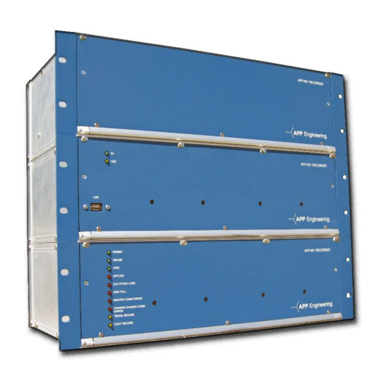
Page 56: Figure 13: App-601 Data Chassis 3D View
PAR, Fault/SER LED Alarm Duration. 10 seconds is the default. CONT RECORD Yellow This LED will illuminate if the system is currently performing any continuous recording function. Figure 13: APP-601 Data Chassis 3D View Hardware 4-19... -
Page 57: Figure 14: App-601 Data Chassis Front View
Figure 14: APP-601 Data Chassis Front View Figure 15: APP-601 Data Chassis Rear View (Blank Panels Shown in Slots 5 & 6, Analog or Event Board can be inserted) Hardware 4-20... -
Page 58: Ethernet Switch
Ethernet Switch The Ethernet switch allows flow of information between the Computer Control chassis, and the Data chassis. The standard Ethernet switch, included with the recorder, is a five or eight port EISK series unmanaged plug and play switch. The EISK switches are intended for commercial and industrial applications. -
Page 59: Table 7: Pin Out
Table 7: Pin Out RJ-45 Usage Not Used Not Used Not Used Not Used (Ports normally assume the internal crossover function, but will automatically adapt to connected devices. Straight instead of crossover cable is preferred. When daisy chaining switches, straight cable is a must.) *CAUTION* The Ethernet Switch is used for the DSP network only. -
Page 60: Networking
Networking The Computer Control Chassis uses two separate network setups. One is for recorder functionality (chassis- to-chassis communication & data transfer) and the second is for communication between the recorder (APP Recorder Software) and the master station (APP ClearView Software). -
Page 61: Installing The Recorder Software
5. Installing the Recorder Software Installing the Recorder Software... -
Page 62: Introduction
To Install the Program Insert the APP Recorder CD in the system computer CD Drive or Thumb Drive in a USB Port. Browse to the APP Recorder.exe file and double click it to start the installation process. -
Page 63: Figure 16: Recorder Configuration Window
13. Click Save in the upper left hand corner of the window. The basic configuration is set. 14. In the APP Recorder window, from the Edit menu, point to Point Assignment Record (PAR), and then click Edit Record. If the Edit Point Assignment Record screen does not appear (Figure 17), and a message that the record does not exist appears, a PAR will need to be established. -
Page 64: Figure 17: Point Assignment Window's Chassis Configuration
16. At the bottom of the Point Assignment window, click the Chassis Config. tab. At the top of the page, enter the name of station or location of the recorder. Next to “#chassis”, enter the sum total of Data chassis. Figure 17: Point Assignment Window’s Chassis Configuration 17. -
Page 65: Startup And Running The App Monitor
Startup and Running the APP Monitor APP Recorder can be setup to automatically start when the computer restarts and using APP Monitor to automatically start if APP Recorder is shutdown. When Monitor is running, APP Recorder will restart within 60 seconds of being closed. -
Page 66: Figure 19: Windows Logon & Setup Window
Figure 19: Windows Logon & Setup Window In the User box, type the user name for the Windows logon of the APP Recorder. In the Password box and the Confirm Password box, type the password for the Windows logon of the APP Recorder. -
Page 67: Using The App Recorder
6.Using the APP Recorder Using the APP Recorder... -
Page 68: Introduction
Introduction The APP Recorder Program must be running for the APP Recorder hardware to operate. The APP Recorder Program contains information and settings that contribute to the Recorder’s versatile, user-friendly, state- of-the-art functionality. APP Recorder Program Functions The APP Recorder Program carries out the following major functions: ... -
Page 69: Figure 20: App Recorder Program Main Window
The Message window displays information related to program startup, program re-initialization, information sent to the APP Recorder Driver, and error messages. In addition, it can display messages sent during a chat session with someone at the master station. ... -
Page 70: Figure 22: Triggers Tab
The Events/SER tab shows the configuration of the event/SER. If you highlight any of the row(s) and then right click, a pop-up menu will display the options, Run SER and Stop SER. You can run or stop a particular event channel SER without re-initializing the APP Recorder. SER Report Tab Figure 24: SER Report Tab The SER Report tab displays channels that are in a stopped or abnormal state. -
Page 71: Setting The Administrator Password
Changing passwords Configuring the APP Recorder software Modifying the Point Assignment Record Modifying the Line Group Record ... -
Page 72: Printing
6.5.3 Printing the Recent Fault Summary You can preview or print a fault summary report for the last recorded fault. If the APP Recorder Program is stopped, and restarted, this function will not work until a new fault record is generated: it does not read prior fault records. -
Page 73: Printing The Recent Fault Summary With A Graph
You can exit the APP Recorder for maintenance or troubleshooting purposes. When you exit the APP Recorder, the APP Driver is automatically exited as well. If you have set an administrator password, then you must enter the password before exiting the APP Recorder. See Setting the Administrator Password for more information. -
Page 74: Configuring The App Recorder
APP Computer Chassis Data Storage Architecture: The APP 601 Computer Chassis includes two storage areas. The C:\ drive is 8, 16, or 32 GB Flash memory. The D:\ drive is typically 500 GB or larger conventional hard drive. These capacities may vary depending on requirements of the customer’s application. -
Page 75: Figure 26: Example Of App 601 Recorder Configuration Window-Main Tab
Recorders will be numbered sequentially. Company Name field, enter any name you would like. This name will appear at the top of the APP Recorder Program main page. At the factory, the name of the company who purchased the system is entered. - Page 76 30 seconds. Therefore, in the case of no communications activity, the APP ClearView program will be the first to initiate a hang up action. Do you want to make the APP Recorder the first program to initiate a hang up action in the event of an unexpected disconnect? If yes, then in the Hang up if connection to ClearView has been idle for X minutes box, type a value less than 10 minutes.
-
Page 77: Setting Up Dial-Up Networking
The following is the procedure to set up DialNet. This procedure is also in Readme.txt located inside of the ClearView directory. To establish dial-up networking, you must complete the setup procedures on both the APP Recorder (server) computer and on the ClearView (client) computer. -
Page 78: Configuring Automatic Tasks
6.7.5 Configuring Automatic Tasks The APP Recorder can perform a variety of automatic tasks, which appear on the window that is shown in Figure 27. By configuring the automatic tasks, you can take full advantage of the APP Recorder’s ability to become an integral part of your substation or plant automation. -
Page 79: Accessing The Automatic Tasks Tab
Figure 27: Recorder Configuration Window —Automatic Tasks Tab 6.7.7 Configuring Automatic Tasks that Occur when a Fault Arrives Call Master, You can configure whether or not the APP Recorder calls the master station, and what type of data it sends about the fault. -
Page 80: Table 10: Configuring Automatic Tasks-Options In The Call Master List
Main tab Report true (Data) and associated data Logic (OR=1, AND =&) (sometimes) Print all analog Data means these only waveforms and check boxes all event graphs only when certain conditions occur Using the APP Recorder 6-14... -
Page 81: Configuring Printing
In the Max # Attempt box, type the number of times the APP Recorder Program will attempt to call the master station, via modem or network, before stopping. Data Means These Only, do you want to limit the type of data sent when a fault occurs? ... -
Page 82: Table 11: Configuring Automatic Tasks-Options In The Print List
If no, then skip to the next step. Do you want to configure the format of printed reports? If yes, continue with the procedure, Configuring the Format of Printed Reports. If no, from the menu bar, click Save. Using the APP Recorder 6-16... -
Page 83: Configuring The Format Of Printed Reports
Yscale Optomized (RMS) This selection prints the RMS value to the right side of each oscillogram printed. Note: Print fewer channels on a page to increase the resolution on the Yscale. Using the APP Recorder 6-17... - Page 84 Spread digital among graphs, if Spread digital check box is not checked, the Analog channels are printed, then the Event Channels, on each page (See Figure 29). With Spread digital check box checked the report shows the digital channels along with the Analog lines together (See Figure 30). Using the APP Recorder 6-18...
-
Page 85: Figure 29: Default Report Format
Figure 29: Default Report Format Figure 30: Report with Spread digital among graphs checked Using the APP Recorder 6-19... -
Page 86: Configuring Email Settings
You can configure the APP Recorder to automatically email fault summary information to the master station. When the APP Recorder sends an email, it sends a plain text e-mail message containing a summary of a fault. The following information is included in the report: ... -
Page 87: Figure 31: Auto Email Setup Window
Contact your network administrator to obtain values for the Outgoing Mail (SMTP), Port#, and User ID fields. Do you want the APP Recorder to automatically email a summary of every fault each time the master station automatically retrieves a fault record or whenever a fault record is automatically called in? ... -
Page 88: Figure 32: Manual Emailing Window
In the Send Email window, click the Message tab. The Message tab appears, as shown in the following figure. From here, you can type an email and manually send it to everyone in the Recipient list. Figure 32: Manual Emailing Window Using the APP Recorder 6-22... -
Page 89: Configuring Ftp Settings
Open the Recorder Configuration window and open the Automatic Tasks tab. Select the FTP check box. Note: You must set this up if you want the APP Recorder to send transient records through FTP. Click the FTP Settings button. The FTP Settings dialog box appears, as shown in the following figure. - Page 90 APP Recorder trace file. 12. Time Between each Retry : Randomized Between, enter the two times in seconds, between which FTP retries should occur. APP Recorder will attempt at random intervals between the range specified, to resend data.
-
Page 91: Figure 34: Ftp Remote Directory Setup Window
FTP settings are incorrect, you will see nothing in the message window. In the tray below the message window you might see error messages. If no, skip to the next step. 18. From the menu bar, click Save. Using the APP Recorder 6-25... -
Page 92: Defining A Boolean Logic Equation
6.7.12 Defining a Boolean Logic Equation You can define a Boolean Logic equation to automatically filter, or limit, when the APP Recorder does any or all of the following: Calls the master system Prints the Fault Summary File and fault-related data ... -
Page 93: Configuring Automatic Ser Reports
Note: You can clear the buffer for troubleshooting or testing purposes. Click Clear FIFO to clear the buffer of any fault record or test file that the APP Recorder is trying to send to the remote directory. 6.7.14 Configuring Automatic SER Reports If a receipt printer is connected to the parallel port of the computer running the APP Recorder, the APP Recorder can automatically print an SER report when a SER (SOE) channel experiences a change of state. -
Page 94: Calling The Master Phone List When Alarms Occur
Open the Recorder Configuration window and open the Automatic Tasks tab. Under the When Alarms Occurred, Do section, do one of the following: If you want the APP Recorder to call the numbers in the Master Phone list, select the Call Master… check box. ... -
Page 95: Figure 36: Master Phone & Network List Window
By default, the first entry that you make is selected, as indicated by the X in the Use column. The entry with the “X” is the number that APP ClearView will call when it connects to or calls the APP Recorder. You can activate multiple phone numbers and/or IP addresses. -
Page 96: Ping Master Every 5 Minutes
Record, General Settings, Recorder Setup tab to have a hard alarm displayed. 6.7.18 Configuring Allowed IPs The APP Recorder includes a security feature that will limit remote connections to the APP Recorder. Only specified IP addresses will be permitted remote access to the APP Recorder. -
Page 97: Printing Recorder Configuration
If your company provides line group information, factory personnel will enter that information into the APP Recorder before shipping it to you. In addition, you can create and edit a Line Group Record can be created or edited via the APP Recorder or the APP ClearView. The line group file can be downloaded from the master station (APP ClearView) to the APP Recorder or vice versa. -
Page 98: Connecting To Clearview
You can manually initiate a phone call connection between the APP Recorder and the master station. The APP Recorder will call the phone numbers or IP addresses that are entered in the Master Phone List. The APP Recorder only calls those numbers/IP addresses that have a checkmark beside them. If more than one number has a checkmark, the recorder will call them in sequential order. -
Page 99: Choosing A Modem
You can leave this window open while you access other functionality in the APP Recorder 6.10.4 Choosing a Modem You can view the currently installed modems and choose which modem the APP Recorder should use. Note: After choosing your modem, you should not need to configure it; the process is automated for you. -
Page 100: Turning On Or Off Dial-Up Networking
Reserve the Memory and defrag the data drive 6.11.1 Viewing Trace Files You can use trace files to help during troubleshooting. There is a separate trace file for the APP Recorder and the APP Driver. Trace files include: ... -
Page 101: Running A Diagnostic Test And Viewing Results
The trace file for the APP Driver appears. To View the All Trace (ATrace) File In the APP Recorder window, from the Maintenance menu, point to Trace Files and click Show All Trace File. The trace file for the APP Driver appears. -
Page 102: Viewing All Ser Abnormal Or Stopped Channels
6.11.4 Performing a Test Run You can perform a test run to test if the APP Recorder is really recording and to check all the channel data. When you perform a test run, the APP Recorder trips, creating a transient COMTRADE record. The COMTRADE records contain a snapshot of all the analog channel signals, and the state of all DFR channels, plus the present status of the event inputs. -
Page 103: Viewing The On Alarms
You can view a list of the alarms that are currently turned on. To View the ON Alarms In the APP Recorder window, from the Maintenance menu, click Show Alarm ON List. The Alarms Currently On window appears. Figure 42: Alarms Currently ON Window 6.11.6 Resetting FID... -
Page 104: Re-Initializing The App Recorder Program
You can re-boot the APP Recorder program to help with troubleshooting. When you reboot, power is momentarily cut to the APP Recorder. The computer and all circuit boards will see a hard power shutdown. Power is cut via a normally closed relay on the data chassis power supply circuit board. -
Page 105: Reserving Memory And Defragging The Data Drive
A Warning message appears. Click Yes. To check if the reserve memory process is finished, look at the APP Recorder trace file. In this file, the message, “Begin Reserve Memory” appears when the reserve memory process starts. The message, “End Reserve Memory” appears when the process finishes. For information, see Viewing Trace Files. -
Page 106: Continuous Recording
Figure 43: Continuous Recording Menu 6.12.1 Viewing the Continuous Recording Status Window You can verify that the APP Recorder is actively calculating quantities and saving data by viewing the status window. The APP Recorder stores the continuous oscillography data and calculated RMS, Frequency, and Phase quantities in the following folders: ... -
Page 107: Saving Oscillograph Data
Figure 44: Continuous Recording Status Window 6.12.2 Saving Oscillograph Data You can save a time slice of data to a file. You can open and view the file with the APP ClearView program. In the APP Recorder window, from the Continuous Recording menu, point to Oscillograph and then click “Save Oscillograph Data…”. -
Page 108: Saving Frequency Data
6.12.3 Saving Frequency Data You can save a time slice of data to a file. You can open and view the file with the APP ClearView program. Figure 46: Save Freq Data File Continuous frequency is calculated using a sliding window. A single frequency data point is calculated using 5000 data samples (total cycles/time). -
Page 109: Saving Rms Data
6.12.4 Saving RMS Data You can save a time slice of RMS data to a file. You can open and view the file with the APP ClearView program. To Save RMS Data In the APP Recorder window, from the Continuous Recording menu, point to RMS and then... -
Page 110: Using Other Tools
6.13.1 Startup and Running the APP Monitor APP Recorder can be set up to automatically start when the computer restarts and using APP Monitor to automatically start if APP Recorder is shutdown. When APP Monitor is running, APP Recorder will restart within 60 seconds of being closed. -
Page 111: Network Path Logon
Figure 49: Network Path Logon This feature is used to automatically log the DFR onto a network drive at APP Recorder Startup or is reinitialized. Fill in the fields shown to achieve connectivity to the desired network drive. To see if connection has been established, go to Windows Directory and see if the desired drive is shown and/or accessible. -
Page 112: Configuring A Dnp3/Modbus Outstation
6.13.3 Configuring a DNP3/Modbus Outstation Configuring DNP-3 or Modbus Protocol You can configure a DNP3 or Modbus outstation for the APP-601 Recorder. The APP-601 Recorder provides the following information through DNP-3 and Modbus: Analog Channel RMS Analog Channel Frequency... -
Page 113: Table 13: Dnp-3 Objects And Variations
Floating Point instead of HEX values to the RTU. Otherwise, for the RTU to receive HEX leave unchecked. From the menu bar, click Save. The APP-601 Recorder accepts the DNP-3 objects and variations shown in the following table. Table 13: DNP-3 Objects and Variations Object... -
Page 114: To Configure A Dnp3/Modbus Outstation Point Mapping Tab
Configuring Modbus In the APP Recorder window, from the Tools menu, click DNP3/Modbus Config. The following window appears. Figure 51: DNP-3/Modbus Configuration Window (Modbus) In the Protocol field, select the protocol Modbus In the This Station ID box, type the Recorder ID, which was setup in the Recorder Configuration window. -
Page 115: Figure 52: Point Mapping
To View the DNP3/Modbus Communication Status You can view the DNP3 communication status while the APP Recorder is running. 1. In the APP Recorder window, from the Tools menu, click DNP3. The DNP-3/Modbus Configuration Window appears as shown in Figure 50. -
Page 116: Emailing A Fault Summary Record
A fault file contains an individual fault record. If a Fault file is stalled in the FTP buffer, you can manually send it via FTP to the host directory. The APP Recorder uses the FTP settings that you configured. For information on the FTP configuration settings, see Configuring FTP Settings on page 6-23. - Page 117 Using the APP Recorder 6-51...
-
Page 118: Configuring A Dsp Board's Ethernet And Ip Address Settings
6.13.9 Configuring a DSP Board’s Ethernet and IP Address Settings Before an APP-601 Recorder leaves the factory, each of its DSP/IRIG boards is programmed with an Ethernet Address, IP Address, Subnet Mask, and Default Gateway. In a centralized or turn-key system, it is highly unlikely the Ethernet or IP Addresses will ever need to be changed. -
Page 119: Configuring A Phasor Measurement Unit (Pmu)
APP Recorder or to a communications device (switch). Auto Neg is the default setting and is used when connected directly to the APP Recorder computer or to an APP Engineering supplied switch. Customer specified programmable switches not set to Auto Negotiate may need to check the 100Mbit and Full Duplex options to successfully communicate with the switch. -
Page 120: Figure 55: Pmu Window
Specify the analog channels To Configure the Point Assignment Record for PMU Data In the APP Recorder window, from the Edit menu, point to Point Assignment Record and then click Edit Record. The Point Assignment Record window appears. Click the General Settings tab. - Page 121 (Va, Vb, Vc, Ia, Ib, Ic, V1, I1, V2, I2, V0, I0). If the phasor for all channels in the DFR should be sent, select the sending format All Analog Channels. Using the APP Recorder 6-55...
-
Page 122: Figure 56: Pmu - Sending Format
12. Send UTC time, If you want to send the time stamp to the PMU in Coordinated Universal Time (UTC), click the check box for Send UTC Time. This will not affect the local time stored on the DFR. Using the APP Recorder 6-56... -
Page 123: Viewing The Help And About Information
Clicking Close does not automatically save the settings. Remember to click Update. 6.15 Viewing the Help and About Information You can view the online help for the APP Recorder. The About information includes the driver version and factory contact information. ... -
Page 124: Using The App Driver
7. Using the APP Driver Using the APP Driver... -
Page 125: Introduction To The App Driver
Introduction to the APP Driver The APP Recorder Driver is the program that manages the physical APP Recorder hardware. You can access the APP Driver from within the APP Recorder program. In the APP Driver, you can view communications between the following items: ... -
Page 126: Reinitializing The App Driver
The results will appear in the upper black area in the information area. Performing a Test Run from the APP Driver You can do a test run from within the APP Recorder or the APP Driver. For more information, see Performing a Test Run in Section 6. -
Page 127: Viewing The Help And About Information
Viewing the Help and About Information You can view the online help for the APP Driver. The information in the About window includes the driver version and factory contact information. Note: If the help files do not answer your question(s), please do not hesitate to contact APP Engineering, Inc. -
Page 128: Using The Oscope
8. Using the OScope Using the OScope... -
Page 129: Introduction To The Oscope
Introduction to the OScope The OScope window is very useful when setting up the APP Recorder for the first time. It allows you to view real-time analog signals, analog trigger status, event status, and to perform analog channel calibration. Viewing the OScope (Oscilloscope) Window... -
Page 130: Events Tab
8.2.2 Events Tab The Events tab shows the status of the event channels. An “O” indicates an open contact and an “X” indicates a closed contact. If the box is green the channel is in a normal state. If the box is red the channel is in an abnormal state. -
Page 131: Yscale Controls
8.2.4 Yscale Controls In the YScale box, you can select from three options for the Y Scale. The following table describes these options. Table 15: OScope Window—Y Scale Options Option Description Full Scale If Full Scale is selected, the displayed Y-axis maximum and minimum will be approximately 70% greater than the channel full scale listed in the Point Assignment Record. -
Page 132: Bottom Tray
To Reinitialize the OScope Window In the APP OScope window, from the File menu, click Reinitialize. Exiting the OScope Window When you exit the OScope window, the APP Recorder returns to its normal, online status. To Exit the OScope Window In the APP OScope window, from the File menu, click Exit. -
Page 133: Figure 61: Dsp Board Communication Status Window
Figure 61: DSP Board Communication Status Window The following table describes the fields that appear in this window. Table 16: DSP Board Communication Status Window—Fields Field Description Time Mark The absolute times of the 1PPS signal for all the DSP boards, are displayed here. -
Page 134: Viewing Stopped/Abnormal Ser Channels
Viewing Stopped/Abnormal SER Channels In the APP OScope window, from the Status menu, click Show Stopped/Abnormal SER Channels. The Stopped/Abnormal SER Channels window appears. Figure 62: Stopped/Abnormal SER Channels Screen On the SER Report tab, channels that are in a stopped or abnormal state appear. The following table explains the letters that appear on this window. -
Page 135: Setting All Analog Channel Inputs To Zero
To Set All Analog Channel Inputs to Zero In the APP OScope window from the menu bar, click Advanced then Set All Analog Channel Inputs to Zero. 8.8.3 Turning On All Alarms and LEDs If you need to test the front panel LED’s and alarm outputs, you can turn them all on simultaneously. When you do this, all of the relay coils will energize and the front panel LED’s should illuminate. -
Page 136: Rebooting The Driver
To Turn on a specific Alarm by its number In the APP OScope window, from the menu bar, click Advanced, then Turn On All Alarms and LEDs, then turn on Alarm #. Enter the number of the desired alarm and click OK. -
Page 137: Calibrating And Un-Calibrating Offsets One Channel At A Time
For a current Channel, a DC offset of 0.00 to 0.03 should be achievable. The offset calibration process creates a file named RxxExCal.ini in path location C:\APP Recorder\Setup. The “xx” in the file name is the unique recorder ID number. This is an ASCII file and can be viewed by doubling clicking it. -
Page 138: Figure 65: External Calibration (Slope) Group
The calibration process creates an ASCII file named RxxExCal.ini in path location C:\APP Recorder\Setup. The “xx” in the file name is the unique recorder ID number. For example, in the file name A1=0,0.999965, A1 is the analog channel number, 0 is the internal calibration factor for the DC offset, and 0.999965 is the external calibration factor. -
Page 139: Other Information
9. Other Information Other Information... -
Page 140: Time Quality
If the clock is synchronized then the fault record tag will show locked. If the clock is un- synchronized then the fault record tag will show unlocked. If there is no signal connected to the APP-601 IRIG input, then the fault record tag will display “No Signal”. -
Page 141: Recommended Maintenance And Calibration
Alarm box in the upper right hand corner of the APP ClearView window displays alarms for APP Recorder. Alarms appear as a red background with the text Alarms On. If an APP Recorder has an alarm, double-click the Alarm box to see which APP Recorder is in alarm. -
Page 142: Time-Based Maintenance
Then enter 240.384 for the CT/PT value, and enter 5 for the Full Scale value (on the secondary 1MW-1V). Click Save in the Point Assignment window. In the APP Recorder, open the OScope (File menu, Show OScope). View the analog channel that is being setup for MW. -
Page 143: Recommended Setup For Mvar Channels (Using 4Ma-12Ma-20Ma Transducer)
349.650 for the CT/PT value, and enter 5 for the Full Scale value (on the secondary 1V=1MVAR.) Click Save on the Point Assignment window. In the APP Recorder, open the OScope (File menu, Show OScope). View the analog channel that has been set up for MVAR. -
Page 144: Recommended Setup For A Current Channel Using A 4Ma-20Ma Transducer (E.g. Measuring Generator Field Current)
1 for the CT/PT value, enter 2000 for the Full Scale value (ABS will automatically = 5000), and enter 2.16 milliohms for the external shunt value. Click Save in the Point Assignment window. In the APP Recorder program, open OScope (File menu, Show OScope). View the analog channel that is being setup with this transducer. -
Page 145: Linux Ubuntu Operating System
Windows operating system and APP Recorder program. It will take a few minutes for the recorder to go on-line. It is possible for the APP Recorder program to start up and display information but the front panel lights indicate an off-line status. In this case, do not do anything. -
Page 146: Stopping The App Recorder Program
Do not shut down the computer chassis power until following the steps below, (if possible). Shut down the APP Recorder program. If the program restarts shut it down again (i.e, it is on a 60-second timer that tries to restart the program if it is not running).
Need help?
Do you have a question about the APP-601 and is the answer not in the manual?
Questions and answers