Sign In
Upload
Manuals
Brands
Anritsu Manuals
Measuring Instruments
VectorStar ME7838D
Anritsu VectorStar ME7838D Manuals
Manuals and User Guides for Anritsu VectorStar ME7838D. We have
2
Anritsu VectorStar ME7838D manuals available for free PDF download: Maintenance Manual, Quick Start Manual
Anritsu VectorStar ME7838D Maintenance Manual (178 pages)
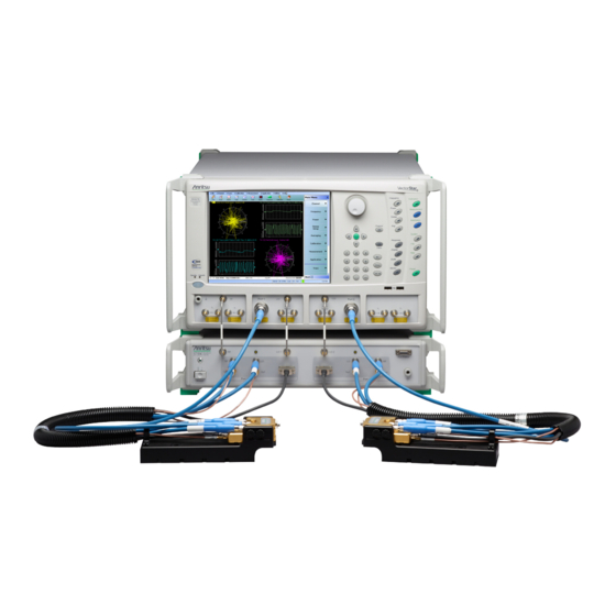
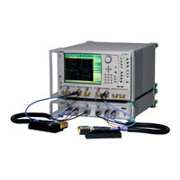
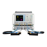
2-Port Broadband/Banded Millimeter-Wave VNA System
Brand:
Anritsu
| Category:
Measuring Instruments
| Size: 6 MB
Table of Contents
Table of Contents
3
Chapter 1 - General Information
9
Introduction
9
Identification Number
9
Contacting Anritsu
9
Related Documentation
10
Product Information, Compliance, and Safety
10
Vectorstar Ms464Xb Series Vector Network Analyzers
10
Vectorstar ME7838 Series 2-Port Bb/Mmw VNA Measurement System
10
Vectorstar ME7838A4 Multiport Bb/MM-Wave VNA Measurement System
10
Vectorstar Mn469Xc Series Multiport VNA Measurement System
11
Calibration, Verification, and System Performance Verification
11
Updates to Manuals
11
Electrostatic Discharge (ESD) Prevention
11
ME7838 Series VNA System Overview
12
ME7838A Standard Broadband VNA System Components - MS4647A Based
12
ME7838A Waveguide Band Configuration System Components - MS4640A Based
15
ME7838A Standard Broadband VNA System Components - MS4647B Based
16
ME7838A Waveguide Band Configuration System Components - MS4640B Based
17
ME7838E Standard Broadband VNA System Components
18
ME7838E Waveguide Band Configuration System Components
19
ME7838D Standard Broadband VNA System Components
20
ME7838G Standard Broadband VNA System Components
21
Recommended Test Equipment
22
Test Equipment - ME7838A/E - Broadband Configuration
22
Test Equipment - ME7838A/E - Waveguide Band Configuration
24
Test Equipment - ME7838D
25
Test Equipment - ME7838G
26
Chapter 2 - Replaceable Parts
29
Introduction
29
ME7838 Series System Replaceable Parts
30
3739A Test Set Replaceable Subassemblies and Parts
32
3739B Test Set Replaceable Subassemblies and Parts
33
3739C Test Set Replaceable Subassemblies and Parts
34
3743A/E and 3744A/E Millimeter-Wave Module Replaceable Parts
36
MA25300A Millimeter-Wave Module Replaceable Parts
36
MA25400A Millimeter-Wave Module Replaceable Parts
36
Chapter 3 - Performance Verification
37
Introduction
37
Calibration and Measurement Conditions
37
ME7838A/E System Verification-Broadband System Configuration
38
Performance Verification Software Overview
38
Verification Result Determination
38
ME7838A/E System Verification Procedure-Broadband System Configuration
39
Equipment Required
39
Special Precautions
39
Procedure
39
ME7838A/E System Verification-Waveguide Millimeter-Wave System Configuration
41
Equipment Required
41
Best Practices for Waveguide Connections
41
Configuration
41
Procedure
43
ME7838D System Verification
51
Performance Verification Software Overview
51
Verification Result Determination
51
ME7838D System Verification Procedure
52
Equipment Required
52
Special Precautions
52
Procedure
52
ME7838G System Verification
54
ME7838G 0.8 MM Coaxial System Verification
54
Performance Verification Software Overview
54
Verification Result Determination
54
ME7838G WR05 Waveguide System Verification
55
3-10 ME7838G 0.8 MM Coaxial System Verification Procedure
56
Equipment Required
56
Special Precautions
56
Procedure
56
ME7838G WR05 Waveguide System Verification Procedure
58
Equipment Required
58
Procedure
58
Measurement Calibration
58
Waveguide Device S-Parameters Measurements
59
Chapter 4 - Theory of Operation
61
Introduction
61
System Description
61
System Components
61
Functional Description of System Components
63
Vectorstar Ms464Xx Vector Network Analyzer
63
3739A Broadband Test Set
65
3739B Broadband Test Set
66
3739C Broadband Test Set
67
3743E Millimeter-Wave Module
68
3744A-EE Millimeter-Wave Module
68
3744E-EE Millimeter-Wave Module
68
3744A-EW Millimeter-Wave Module
68
3744E-EW Millimeter-Wave Module
69
MA25300A Millimeter-Wave Module
69
MA25400A Millimeter-Wave Module
69
ME7838A System Operation-Broadband Configuration
70
Stimulus Signal Generation
70
Test Signal Processing
70
ME7838A System Operation-Waveguide Band Configuration
71
Stimulus Signal Generation
71
Test Signal Processing
71
ME7838E System Operation-Broadband Configuration
72
Stimulus Signal Generation
72
Test Signal Processing
72
ME7838E System Operation-Waveguide Band Configuration
73
Stimulus Signal Generation
73
Test Signal Processing
73
ME7838D System Operation
74
Stimulus Signal Generation
74
Test Signal Processing
74
4-10 ME7838G System Operation
75
Stimulus Signal Generation
75
Test Signal Processing
75
Chapter 5 - Adjustment
77
Introduction
77
LO Level Calibration
77
Equipment Required
77
Procedure
77
ALC Level Calibration
82
Equipment Required
82
Setup Procedure
83
ALC Calibration Procedure-Broadband Configuration
87
ALC Calibration Procedure-Banded Millimeter-Wave Configuration
90
Chapter 6 - Troubleshooting
95
Introduction
95
General Safety Warnings
95
Troubleshooting Strategy
96
Suggested Troubleshooting Steps
96
General Troubleshooting of the System
96
Procedure
96
Troubleshooting Test - VNA Source and lo Power Level Check
98
Equipment Required
98
Procedure
98
Troubleshooting Test - Non-Ratio Power Level Check
100
Equipment Required
100
Procedure
100
General Troubleshooting of the 3739A Test Set
101
Suggested Troubleshooting Steps
101
Troubleshooting Test - 3739A Power Supply DC Check
102
Equipment Required
102
Procedure
102
Troubleshooting Test - 3739A A1 Bias Control PCB DC Bias Check
104
Equipment Required
104
Procedure
104
6-10 Troubleshooting - 3739A Test Set Port Power Level Check
105
Equipment Required
105
Procedure
105
General Troubleshooting of the 3739B/C Test Set
107
Suggested Troubleshooting Steps
107
6-12 Troubleshooting Test - 3739B/C Power Supply DC Check
108
Equipment Required
108
Procedure
108
6-13 Troubleshooting Test - 3739B/C A1 Bias Control PCB DC Bias Check
111
Equipment Required
111
Procedure
111
6-14 Troubleshooting - 3739B/C Test Set Port Power Level Check
112
Equipment Required
112
Procedure
112
Chapter 7 - Removal and Replacement Procedures for 3739A
115
Disassembly Procedure - Power, Disconnect, and Covers
115
Reassembly Procedure - Power, Disconnect, and Covers
118
Replaceable Part Chassis Locations
121
Replacement Parts
123
Reference Figure
123
Replacement Procedure
123
A1 Bias Control PCB Assembly - ND73163<R
125
Replacement Parts
125
Reference Figures
125
Replacement Procedure
127
Module Replacement Basics
129
Basic Module Removal Procedure
129
Basic Module Re-Installation Procedure
129
A100 - ND73159<R> and A105 - ND73160<R> lo Amplifier Modules and Bracket Assembly
130
A101 - ND73161<R> and A106 - ND73162<R> Modulator and Bracket Assembly
131
A102 and A107 Isolator Modules - 3-1000-58 and Bracket Assembly
132
A103 RF Amplifier Module - ND73158<R> and Bracket Assembly
133
A104 SPDT Switch Module - 70242<R> and Bracket Assembly
134
Module Replacement Sequence
135
First Procedure
135
Last Procedure
135
Rear Panel Fan Assembly - ND73164
138
Required Tools
138
Reference Figures
138
Replacement Procedure
139
Front Panel Assembly - ND73169 - 71894
140
Replacement Part
141
Replacement Procedure
141
Chapter 8 - Removal and Replacement Procedures for 3739B and 3739C
145
Disassembly Procedure - Power, Disconnect, and Covers
145
Reassembly Procedure - Power, Disconnect, and Covers
148
Replaceable Part Chassis Locations
151
Power Supply - 3-40-183
151
Replacement Parts
153
Reference Figure
153
Replacement Procedure
154
A1 Bias Control PCB Assembly
155
Replacement Parts
155
Replacement Procedure
155
Module Replacement
158
General Module Removal Procedure
158
General Module Installation Procedure
158
A100 and A101 - ND75883<R> or 3-ND75883<R> Doubler Modules
159
A103 - ND75884<R> or 3-ND75884<R> RF Amplifier Module
160
A105 - ND75885<R> or 3-ND75885<R> and A106 - ND75886<R> or 3-ND75886<R> Amplifier Modules
161
A104 SPDT Switch Module - 70242<R> or 3-70742<R> and Bracket Assembly
162
A104 Assembly Detail
163
Rear Panel Fan Assembly - ND73164 or 3-ND73164
165
Required Tools
165
Reference Figures
165
Replacement Procedure
166
Front Panel Assembly
167
Replacement Parts
167
Procedure
167
Replacement Procedure
168
Appendix A - Test Records
173
Introduction
173
ME7838A Millimeter-Wave Configuration VNA System Test Record
174
Instrument Information
174
Directivity Verification
174
Source Match Verification
174
ME7838G WR05 S-Parameter Measurements Test Record
175
Instrument Information
175
S-Parameter Measurements
175
Advertisement
Anritsu VectorStar ME7838D Quick Start Manual (20 pages)
2-Port Broadband/Banded Millimeter-Wave System
Brand:
Anritsu
| Category:
Measuring Instruments
| Size: 4 MB
Advertisement
Related Products
Anritsu VectorStar ME7838D4
Anritsu VectorStar ME7838 Series
Anritsu VectorStar ME7838A
Anritsu VectorStar ME7838G
Anritsu VectorStar ME7838 4 Series
Anritsu VectorStar ME7838G4
Anritsu VectorStar ME7838 4X Series
Anritsu VectorStar ME7838E4X
Anritsu VectorStar ME7838AX
Anritsu VectorStar ME7838E
Anritsu Categories
Measuring Instruments
Test Equipment
Portable Generator
Control Unit
Thermometer
More Anritsu Manuals
Login
Sign In
OR
Sign in with Facebook
Sign in with Google
Upload manual
Upload from disk
Upload from URL