Sign In
Upload
Manuals
Brands
Anritsu Manuals
Measuring Instruments
VectorStar ME7838A4X
Anritsu VectorStar ME7838A4X Manuals
Manuals and User Guides for Anritsu VectorStar ME7838A4X. We have
1
Anritsu VectorStar ME7838A4X manual available for free PDF download: Maintenance Manual
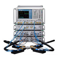
Anritsu VectorStar ME7838A4X Maintenance Manual (138 pages)
Multiport Broadband Vector Network Analyzers
Brand:
Anritsu
| Category:
Measuring Instruments
| Size: 7 MB
Table of Contents
Table of Contents
3
Chapter 1 - General Information
9
Introduction
9
Identification Number
9
Contacting Anritsu
10
Related Manuals and Documentation
10
Product Information, Compliance, and Safety
10
Ms464Xa Series Vector Network Analyzer
10
Vectorstar™ Ms464Xb Series Vector Network Analyzers
10
Vectorstar ME7838 Series 2-Port Bb/Mmw VNA Measurement System
10
Vectorstar™ Me7838X4 Multiport Bb/Mmwave VNA Measurement System
11
Vectorstar Mn469Xc Series Multiport VNA Measurement System
11
Calibration, Verification, and System Performance Verification
11
Updates to Manuals
11
Electrostatic Discharge (ESD) Prevention
12
Me7838X4 VNA System Overview
12
ME7838A4 Standard Broadband VNA System Components - MS4647A-Based
13
ME7838A4 Waveguide Band Configuration System Components - MS4640A-Based
14
ME7838A4/A4X Standard Broadband VNA System Components - MS4647B-Based
15
ME7838A4/A4X Waveguide Band Configuration System Components - MS4640B-Based
16
ME7838E4/E4X Standard Broadband VNA System Components - MS4647B-Based
17
ME7838E4/E4X Waveguide Band Configuration System Components - MS4640B-Based1-10
18
ME7838D4 Standard Broadband VNA System Components - MS4647B-Based
19
ME7838G4 Standard Broadband VNA System Components - MS4647B-Based
20
Recommended Test Equipment
21
Test Equipment - ME7838A4/A4X/E4/E4X- Broadband Configuration
21
Test Equipment - ME7838A4/A4X/E4/E4X - Waveguide Band Configuration
23
Test Equipment - ME7838D4
24
Test Equipment - ME7838G4
26
Chapter 2 - Replaceable Parts
29
Introduction
29
Me7838X4/X4X System Replaceable Parts
29
3736B Test Set Replaceable Subassemblies and Parts
30
3743A/AX/E/EX and 3744A/E Mmwave Module Replaceable Parts
32
MA25300A Mmwave Module Replaceable Parts
32
MA25400A Mmwave Module Replaceable Parts
32
Chapter 3 - Performance Verification
33
Introduction
33
Calibration and Measurement Conditions
33
ME7838A4/A4X/E4/E4X Performance Verification - Broadband System Configuration
34
Performance Verification Software Overview
34
Verification Result Determination
34
ME7838A4/A4X/E4/E4X System Verification Procedure - Broadband System Configuration
35
Special Precautions
35
Procedure
35
ME7838A4/A4X/E4/E4X Performance Verification - Mmwave Configuration
37
Equipment Required
37
Best Practices for Waveguide Connections
37
ME7838A4/A4X/E4/E4X System Verification Procedure - Mmwave System Configuration
39
Procedure
39
Measurement Calibration Setup
39
Port 1 Directivity Verification
43
Port 2 Directivity Verification
45
Port 3 Directivity Verification
45
Port 4 Directivity Verification
45
Port 1 Source Match Verification
46
Port 2 Source Match Verification
47
Port 3 Source Match Verification
47
Port 4 Source Match Verification
47
ME7838D4 System Verification Procedure
49
Equipment Required
49
Special Precautions
49
Procedure
49
ME7838G4 Performance Verification
51
ME7838G4 0.8 MM Coaxial System Verification
51
Performance Verification Software Overview
51
Verification Result Determination
51
ME7838G4 WR05 Waveguide System Verification
52
ME7838G4 0.8 MM Coaxial System Verification Procedure
53
Equipment Required
53
Special Precautions
53
Procedure
53
3-10 ME7838G4 WR05 Waveguide System Verification Procedure
55
Equipment Required
55
Procedure
55
Measurement Calibration
55
Waveguide Device S-Parameters Measurements
57
Chapter 4 - Theory of Operation
59
Introduction
59
System Description
59
System Components
59
Me7838X4/X4X Broadband Systems
59
Me7838X4 Banded Systems
59
Functional Description of System Components
61
Vectorstar Ms464Xa/B Vector Network Analyzer
61
Mn469Xc Multiport Test Set
63
3736B Broadband Test Set
64
3739C Broadband Test Set
65
Test Set Drive Characteristics
65
3743A/AX Broadband Mmwave Module
66
3743E/EX Broadband Mmwave Module
66
3744A-EE Banded Mmwave Module
66
3744A-EW Banded Mmwave Module
66
3744E-EW Mmwave Module
66
MA25300A Mmwave Module
67
MA25400A Mmwave Module
67
ME7838A4/A4X System Operation - Broadband Configuration
68
Stimulus Signal Generation
68
Test Signal Processing
68
ME7838A4 System Operation - Waveguide Band Configuration
68
Test Signal Processing
69
ME7838E4 System Operation - Broadband Configuration
69
Stimulus Signal Generation
69
ME7838E4 System Operation - Waveguide Band Configuration
70
Stimulus Signal Generation
70
Test Signal Processing
70
ME7838D4 System Operation
71
Stimulus Signal Generation
71
Test Signal Processing
71
4-10 ME7838G4 System Operation
71
Test Signal Processing
72
Chapter 5 - Adjustment
73
Introduction
73
4-Port to 2-Port Conversion Hints
73
LO Level Calibration (ME7838A4/D4/E4)
74
Equipment Required
74
Procedure
74
LO Level Calibration (ME7838A4X/E4X/G4)
79
Equipment Required
79
Procedure
79
ALC Level Calibration
84
Equipment Required
84
Setup Procedure
85
ALC Calibration Procedure - Broadband Configuration
89
ALC Calibration Procedure - Banded Mmwave Configuration
91
Chapter 6 - Troubleshooting
95
Introduction
95
General Safety Warnings
95
Troubleshooting Overview
96
Suggested Troubleshooting Strategy
96
General Troubleshooting of the Me7838X4 System
97
Vna/Module/Test Set Fault Isolation
97
Troubleshooting Test - VNA RF Source and lo Power Level Checks
99
Equipment Required
99
Preliminary Steps
99
RF Port Output Level Check
99
LO1 Port Output Level Check
101
LO2 Port Output Level Check
101
Troubleshooting Test - Non-Ratio Power Level Check
102
Equipment Required
102
Procedure
102
3736B Test Set Troubleshooting
104
General Troubleshooting Steps
104
3736B Power Supply DC Check
104
3736B A1 Bias Control PCB DC Bias Check
106
3736B Test Set RF and lo Port Power Level Check
107
3739C Test Set Troubleshooting
108
Mn469Xc Test Set Troubleshooting
108
Chapter 7 - Removal and Replacement Procedures for 3736B
109
Introduction
109
Required Tools
109
Disassembly Procedure - Power, Disconnect, and Covers
109
Reassembly Procedure - Covers, Reconnect, and Power
112
Replaceable Parts - Chassis Locations
113
Power Supply - 3-40-183
116
A1 Bias Control PCB Assembly
117
Module Replacement
119
General Module Removal Procedure
119
General Module Installation Procedure
119
A100 and A101 - ND75883<R>/3-ND75883<R> Doubler Modules
120
A103 - ND75884<R>/3-ND75884<R> RF Amplifier Module
121
A105 - ND75885<R>/3-ND75885<R> and A106 - ND75886<R>/3-ND75886<R> Amplifier Modules
122
A104 SPDT Switch Module - 70242<R>/3-70242<R> and Bracket Assembly
123
A104 Assembly Detail
124
A107, A108, A109 Power Divider Modules
125
A1, A2, B1, B2 - Coaxial Switch - ND81416/3-ND81416
126
Rear Panel Fan Assembly - 3-ND73164
128
7-10 Front Panel Assembly
129
Appendix A - Test Records
133
Introduction
133
Me7838X4 Banded Mmwave Configuration VNA System Test Record
134
Instrument Information
134
Directivity Verification
134
Source Match Verification
134
ME7838G4 WR05 S-Parameter Measurements Test Record
135
Instrument Information
135
S-Parameter Measurements
135
Advertisement
Advertisement
Related Products
Anritsu VectorStar ME7838A
Anritsu VectorStar ME7838A4
Anritsu VectorStar ME7838AX
Anritsu VectorStar ME7838D
Anritsu VectorStar ME7838E
Anritsu VectorStar ME7838E4
Anritsu VectorStar ME7838D4
Anritsu VectorStar ME7838 4 Series
Anritsu VectorStar ME7838G4
Anritsu VectorStar ME7838 4X Series
Anritsu Categories
Measuring Instruments
Test Equipment
Portable Generator
Control Unit
Thermometer
More Anritsu Manuals
Login
Sign In
OR
Sign in with Facebook
Sign in with Google
Upload manual
Upload from disk
Upload from URL