Sign In
Upload
Manuals
Brands
Anritsu Manuals
Measuring Instruments
MS46122A/B-010
Anritsu MS46122A/B-010 Manuals
Manuals and User Guides for Anritsu MS46122A/B-010. We have
1
Anritsu MS46122A/B-010 manual available for free PDF download: Manual
Anritsu MS46122A/B-010 Manual (208 pages)
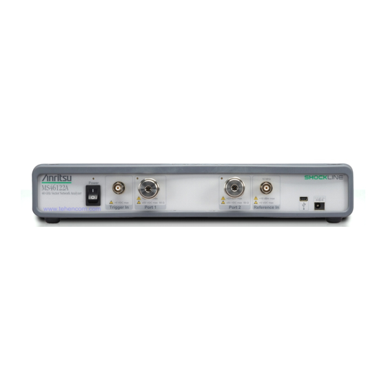
ShockLine MS46122A/B and MS46322A/B Series, Vector Network Analyzer
Brand:
Anritsu
| Category:
Measuring Instruments
| Size: 16 MB
Table of Contents
Table of Contents
3
Chapter 1-Calibration Overview
9
Manual Scope
9
Chapter Summary
9
Related Documentation
9
Product Information, Compliance, and Safety
9
Shockline™ MS46122A/B Vector Network Analyzers
9
Shockline™ MS46322A/B Vector Network Analyzers
9
Calibration, Verification, and System Performance Verification
9
Calibration, Verification, and System Performance Verification
10
Calibration Kits, Verification Kits, and Test Port Cables
11
Calibration/Verification Equipment Part Numbers and General Specifications
11
Autocal Automatic Calibration Modules
13
Calibrations Available
13
SOLT/SOLR Kits (365Xx)
14
Offset Short Waveguide Kits (3655X)
14
Microstrip/Coplanar Waveguide Kits for the UTF (36804-XXX)
14
Calibration Algorithms
15
About Calibration
15
Match
15
Directivity
15
Frequency Response
15
Calibration Types
16
Calibration Algorithms
17
Calibration Setup
18
Frequency Start, Stop, and Number of Points
18
IF Bandwidth, Averaging and Power
18
Types of Calibrations
18
Full 2 Port
18
Full 1 Port
18
Path 2 Port (Forward or Reverse)
19
Frequency Response (Reflection Response and Transmission Frequency Response)
19
Line Types (Transmission Media)
21
Connector Precautions
23
Pin Depth
23
Pin Depth Tolerance
23
Over-Torquing Connectors
24
Teflon Tuning Washers
24
Mechanical Shock
24
Connector Cleaning Instructions
25
Required Cleaning Items
25
Cleaning Procedure
25
Chapter 2-Automatic Calibration Procedures
29
Chapter Overview
29
Automatic Calibration Introduction
29
Transfer Calibration
29
Calibration Accuracy
29
Automatic Calibration Terms
30
Insertable and Non-Insertable Devices
30
Auto-Sense
30
Characterization File
30
Available Calibrator Modules and Adapters
32
Autocal Modules and Adapters
33
Smartcal Modules and Adapters
33
Autocal Components
33
Smartcal Module
34
Connector Care
34
Calibration Parameters and Types
34
Adapter Removal
35
Through Options
35
Smartcal Test Port 1 / Port 2 Naming Assignments
35
Autocal Test Port Left/Right Naming Assignments
35
MS46122A/B Typical Calibrator Connections
36
MS46322A/B Typical Calibrator Connections
37
Using the Calibration Module
38
Copying the Calibrator Characterization File
40
Procedure
40
Loading a Previously Stored Autocal Characterization
41
Procedure
41
Pre-Calibration Instrument Setup
42
Segmented Sweep
42
IF Bandwidth (IFBW) and Averaging
42
Example Procedure
42
Calibration - Full Two Port - Internal through
45
Required Equipment
45
Procedure
45
Calibration - Two Port Cal - True through
50
Required Equipment
50
Procedure
50
Connect the True through
54
Calibration Module Characterization
57
Characterization
57
Adapter Removal - M-M or F-F Reference Plane
58
Adapter Removal Overview
58
Required Equipment
58
Prerequisites
58
Procedure
58
Chapter 3 -SOLT/SOLR Calibration
63
SOLT/SOLR Introduction
63
Definitions
63
Shorts
63
Opens
63
Loads
63
Thru
63
Reciprocal
63
SOLT/SOLR Calibration
63
Chapter 4-Offset Short (SSLT) Calibration
73
SSLT Introduction
73
SSLT Calibration Example
75
Chapter 5-Triple Offset Short (SSST) Calibration
77
SSST Introduction
77
SSST and Reflectivity Error Terms
77
SSST Calibration Example
80
Chapter 6-LRL/LRM Calibration
83
LRL/LRM Introduction
83
LRL/LRM Comparison
83
LRL - Line-Reflect-Line
83
LRM - Line-Reflect-Match
83
Reflection Offset Length and Reflection Type
88
LRL/LRM Calibration Step-By-Step Example
89
Procedure
90
Hints and Suggestions
93
Chapter 7-Adapter Removal Calibrations
95
Introduction
95
Two Related Sets of Reference Planes
95
Caveats and Limitations
96
Performing an Adapter Removal
99
Example Adapter Removal
100
Chapter 8-Other Calibration Procedures
103
Overview of Other Calibration Procedures
103
Through (Thru) Update
103
Interpolation
104
Hybrid Calibrations
107
Chapter 9-Calibration And Measurement Enhancements
109
Chapter Overview
109
Chapter Overview
110
Embedding/De-Embedding (E/DE)
111
Embedding Tasks
111
De-Embedding Tasks
111
Embedding On/Off Control
112
Types of E/DE Networks
115
Entry Mode for Resistive Elements
116
Entry Mode for Transmission Lines
117
Entry Mode for S2P Defined File-Based Networks
118
Saving and Recalling Embedding Network Configuration
119
Reference Plane Control
120
Auto Button Functions
120
Impedance Transformation
122
Processing Order
123
Reference Plane Processing Sequence
123
Group Delay Processing Sequence
123
Conversions
124
Chapter 10-Verification
127
Introduction to Verification
127
Basic Concepts
127
Hardware Level
127
Intermediate System Level
127
Comparison to Known Devices
127
Metric of Comparison
128
Verification Kit Creation Process
129
Verification Kit Components
130
No Verification with Calibration Kits
130
Verification Kit Software
132
Chapter 11-Measurement Setup Requirements
133
Chapter Overview
133
Channels and Traces Introduction
133
Channel Concept
133
Trace Concept
133
Measurement General Concepts
134
Per-System Variables
134
Channels and the Channel Menu
135
Traces
138
Per-Trace Variables
140
Complex Trace Setup Example
141
Markers Overview
142
Marker Button Label Changes
142
Marker Unit Changes
142
Reference Marker off or on
142
Turning Individual Markers off and on
142
Turning All Markers on
142
Turning All Markers off
143
Naming Conventions for Marker Buttons and Toolbars
143
Position Marker(S)
143
Hold Functions
145
Overview of Limit Lines
146
Limit Lines
146
Limit Test
146
Test Result Sign
147
Limit Line
147
Limit Fail Signal
147
Editing Limit Lines
147
Edit Limit Line Menu
147
Ripple Limit Lines
149
Response Menu
151
Averaging and Smoothing
152
Overview
152
Chapter 12-Measurement - Time Domain (Option 002)
155
Chapter Overview
155
Introduction
155
Basic Time Domain Modes
156
General Concepts
157
Chirp-Z Transform
157
Defects as Impulse Functions in the Time Domain
157
One-Way or Round Trip Time
157
Low Pass Mode
158
Range Setup Menu Functions
159
DC Term Menu
160
Window Shape Menu
161
Bandpass Mode
165
Gating
169
Gate Menu
169
DUT Example - Gate and Window Nominal
171
Other Frequency-With-Time-Gate Calculation Items
173
Saving Gated Results
175
Chapter 13-Measurement - Sweep Types
177
Chapter Overview
177
Introduction
177
Setting up Traditional Frequency Sweeps (Linear and Log)
178
Maximum and Minimum Power Settings
178
Frequency-Based Segmented Sweep
179
Index-Based Segmented Sweep
183
Chapter 14-E/O And O/E Converter Measurements
185
Chapter Overview
185
Introduction and Background
186
Device Response
189
Measurements/(O/E-E/O) Menu
190
Measurement Setups and Considerations
191
Optical Linearity
191
Laser Power and Photodetector Bias Sequencing
191
Optical Fiber Lengths
191
Modulator Bias Control
192
Connector Care
192
Example 2-Port Procedures
193
Uncertainties
198
References
199
Summary
199
Chapter 15-Maximum Efficiency Analysis (MEA) Measurements
201
Overview
201
Introduction
201
Software Setup for Maximum Efficiency Analysis
202
Advertisement
Advertisement
Related Products
Anritsu MS46122A/B-020
Anritsu MS46122A/B-040
Anritsu ShockLine MS46122A Series
Anritsu ShockLine MS46122A-010
Anritsu ShockLine MS46122A-020
Anritsu ShockLine MS46122A-040
Anritsu ShockLine MS46122B Series
Anritsu ShockLine MS46121B Series
Anritsu ShockLine MS46121B-004
Anritsu ShockLine MS46121B-006
Anritsu Categories
Measuring Instruments
Test Equipment
Portable Generator
Control Unit
Thermometer
More Anritsu Manuals
Login
Sign In
OR
Sign in with Facebook
Sign in with Google
Upload manual
Upload from disk
Upload from URL