Sign In
Upload
Manuals
Brands
Anritsu Manuals
Measuring Instruments
MP2100A BERTWave
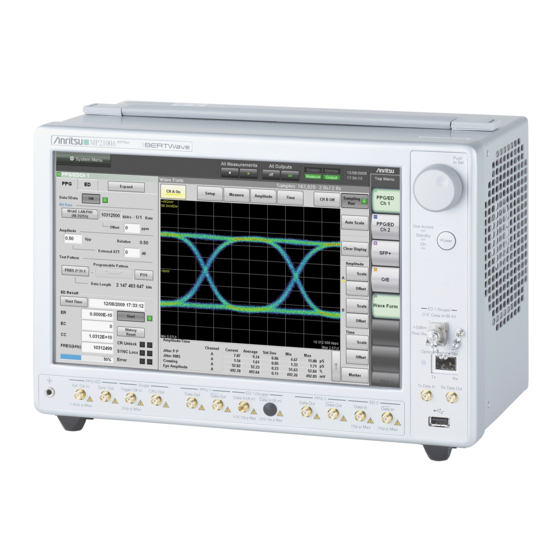
Anritsu MP2100A BERTWave Manuals
Manuals and User Guides for Anritsu MP2100A BERTWave. We have
1
Anritsu MP2100A BERTWave manual available for free PDF download: Operation Manual
Anritsu MP2100A BERTWave Operation Manual (428 pages)
Brand:
Anritsu
| Category:
Measuring Instruments
| Size: 8 MB
Table of Contents
Table of Contents
26
For Safety
3
About this Manual
23
Table of Contents
26
Chapter 1 Outline
31
Bertwave Types
32
Introduction of Bertwave Series
32
Options
33
Optional Accessories
38
Features
39
Intended Use
40
Explanation of Technical Terms
44
Technical Terms
44
Abbreviation
55
Chapter 2 Before Use
57
Unpacking
58
Unpacking and Installation
58
Installation
59
Part Names
63
Rear Panel
65
Side Panel
66
Power Connection
67
Power Requirements
67
Connecting Power Cord
68
Connecting Peripheral Devices
69
Connecting Remote Control Devices
70
Cautions on Handling Optical Fiber Cables
71
Connecting Coaxial Cable
73
Installing Optical Transceiver
74
Installing Optical Transceiver
75
Removing Optical Transceiver
76
Power-On
77
Turning Power On/Off
77
Power-Off
79
Using Touch Panel and Rotary Knob
81
Displaying Windows Desktop
82
Setting Control Panel
82
Setting Control Panel
83
Using External Monitor
84
Configuring Power Options
86
Setting Interface for Remote Control
87
To Display Setup Window
87
To Set GPIB
88
To Set Ethernet
89
Precautions for Preventing Damage
92
Precautions on Electrostatic Discharge and Electrical Overstress
92
Precautions When Using Bias-T
96
Chapter 3 Connecting with DUT
99
Measuring Bit Error Rate
100
Measuring Waveform
106
Simultaneously Measuring Bit Error Rate and Waveform
112
Chapter 4 Screen Operation
115
Screen Configuration
116
Data Input Method
120
Setting System Menu
123
Multi-Channel Signal Output
130
Simultaneous Measurement Start and Stop at Multi-Channels
131
Displaying Date/Time and Status
132
Procedures at System Alarm
133
Chapter 5 Generating Pulse Signal
135
List of Setting Items
136
Setting Restrictions
143
Procedure for Generating Pulse Signal
144
Procedure of Generating Pulse Signal
144
Setting Reference Clock
145
Setting Output Waveform
150
Setting Patterns
154
Inserting Bit Error
159
Setting Sync Output
160
Setting Clock Output
164
Chapter 6 Measuring Bit Error
167
Function List
168
Setting Restrictions
177
Procedure of Measuring Bit Error Rate
179
Setting Conditions for Error Detection
180
Setting Measurement Conditions
192
Measurement Result
195
Saving Measurement Results
196
Chapter 7 Observing Waveform
199
Eye/Pulse Scope Screen
200
Sampling Scope Features
200
Description of Items on the Eye/Pulse Scope Window
201
Setting Item List
210
Setting Restrictions
217
Measurement Procedure
218
Calibrating Level
219
Calibrating Sampling Scope
219
Performing Self Test
222
Setting Clock Recovery and Rate
224
Setting Clock Recovery Unit
225
Setting Bit Rate
228
Setting Clock Rate and Divide Rate
229
Setting Data Collection Method
230
Setting Pattern Length
235
Collecting Data
236
Adjusting Scale Automatically
238
Adjusting Screen Scale
238
Adjusting Vertical-Axis of Screen
240
Adjusting Horizontal-Axis of Screen
242
Adjusting External Attenuator
243
Measuring Waveform
244
Amplitude and Time Measurements
245
Displaying Histogram
250
Executing Mask Test
253
Using Marker
262
Waveform Math Calculation
264
Using Trace Memory
265
Displaying a Label
266
Saving Measurement Results
267
Chapter 8 Operating Optical Interface
275
Optical Interface Types
276
Function List
280
Operating Optical Transceiver
280
Optical Transceiver Types
282
Connection between Panel Connector and Optical Transceiver
283
Function List
284
Operating O/E Converter
284
Adjustment Required When Changing the Wavelength Bands
288
Calibration of O/E Module
288
Chapter 9 Performance Test
291
Apparatus Required for Performance Test
292
Performance Test for Pulse Pattern Generator
292
Operating Frequency Range
293
Waveform
294
Full Rate Clock Output
296
Apparatus Required for Performance Test
297
Performance Test for Error Detector
297
Operating Frequency
298
Input Level
300
Pattern
303
Error Detection
304
Apparatus Required for Performance Test
306
Performance Test for Sampling Scope
306
Amplitude Accuracy
307
Apparatus Required for Performance Test
310
Performance Test for Optical Interface (O/E Converter)
310
Optical Power Meter
311
Chapter 10 Maintenance
313
Daily Maintenance
314
Replacement of Optical Connector
315
Optical Connector/Optical Adapter Cleaning
317
Displaying Software Version
320
Updating Software
322
Touch Panel Position Calibration
323
Cautions on Storage
325
Transporting and Disposal
326
Advertisement
Advertisement
Related Products
Anritsu MP2101A BERTWave PEl MP2102A BERTWave SS
Anritsu MP1632C
Anritsu Bit Master MP1026B
Anritsu MP1595A
Anritsu MP1797A
Anritsu MP1220A
Anritsu SQA-R MP1900A
Anritsu MP1900A Series
Anritsu MP1570A
Anritsu Bit Master MP1026A
Anritsu Categories
Measuring Instruments
Test Equipment
Portable Generator
Control Unit
Thermometer
More Anritsu Manuals
Login
Sign In
OR
Sign in with Facebook
Sign in with Google
Upload manual
Upload from disk
Upload from URL