Table of Contents
Advertisement
Quick Links
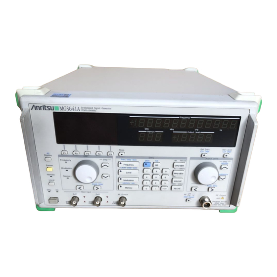
MG3641A/MG3642A
Synthesized Signal Generator
Option 23: Pattern Generator
Operation Manual
Fifth Edition
• For safety and warning information, please read this
manual before attempting to use the equipment.
• Additional safety and warning information is provided
within the MG3641A/MG3642A Synthesized Signal
Generator Operation Manual. Please also refer to this
document before using the equipment.
• Keep this manual with the equipment.
ANRITSU CORPORATION
Document No.: M-W1389AE-5.0
Advertisement
Table of Contents

Subscribe to Our Youtube Channel
Related Manuals for Anritsu MG3641A


Summary of Contents for Anritsu MG3641A
- Page 1 • For safety and warning information, please read this manual before attempting to use the equipment. • Additional safety and warning information is provided within the MG3641A/MG3642A Synthesized Signal Generator Operation Manual. Please also refer to this document before using the equipment.
- Page 2 Safety Symbols To prevent the risk of personal injury or loss related to equipment malfunction, Anritsu Corporation uses the following safety symbols to indicate safety-related information. Ensure that you clearly understand the meanings of the symbols BEFORE using the equipment.
- Page 3 Notes On Export Management This product and its manuals may require an Export License/Approval by the Government of the product's country of origin for re-export from your country. Before re-exporting the product or manuals, please contact us to confirm whether they are export-controlled items or not. When you dispose of export-controlled items, the products/manuals need to be broken/shredded so as not to be unlawfully used for military purpose.
- Page 4 CE Conformity Marking Anritsu affixes the CE Conformity marking on the following product(s) in accordance with the Council Directive 93/68/EEC to indicate that they conform to the EMC and LVD directive of the European Union (EU). CE marking 1. Product Model...
- Page 5 MG3641A/MG3642A, the applied directive and standards of this unit conform to those of the MG3641A/MG3642A main frame. PS: About main frame Please contact Anritsu for the latest information on the main frame types that MG3641A/MG3642A-23 can be used with.
-
Page 7: Table Of Contents
Table of Contents Table of Contents........... Section 1 Overview ..........1.1 Product Overview ............... 1.2 Devices Configuration ..............1.3 Specifications ................Section 2 Preparation Before Use ....... 2.1 Data and Clock Connectors Labeling ......... 2.2 Connection ................. Section 3 Operation Overview ......Section 4 Detailed Description ...... -
Page 9: Section 1 Overview
Besides, when no data pattern is delivered, the idle pattern can be delivered. Various FSK modulated waves can be output by combining with the FSK encoder which is optionally built in MG3641A/ MG3642A. In addition, this Pattern Generator can be used as a modulated signal source of the optional built-in pulse modulator. -
Page 10: Specifications
Resolution: 1 bps Send rate Accuracy: As same as the reference generator frequency of MG3641A/MG3642A units. 1-bit NRZ output (corresponding to two values): Sequentially output by 1-bit starting from the first bit into Data 2 Output. The Data 2 Output logic is fixed to “0”. -
Page 11: Section 2 Preparation Before Use
The preparations for using the Pattern Generator are described here. 2.1 Data and Clock Connectors Labeling Pattern Generator outputs data and clock signals by using the Int Mod Cont 1, 2, and 3 connectors on the MG3641A/ MG3642A rear panel. Each connector is allocated as follows:... -
Page 12: Connection
Section 2 Preparation Before Use 2.2 Connection When both Pattern Generator and FSK Encoder are implemented, the Int Mod Cont connections are as follow: DATA PATTERN GENERATOR FSK ENCODER Output ON/OFF FSK Encoder ON/OFF Data 2 Output Data 2 Input Data 2 Output Data 2... - Page 13 Connect them in the shortest distance by using a coaxial cable that is firmly shielded using for example a double-woven sheath. In addition, set the pulse modulator input impedance to High (600 Ω). MG3641A/MG3642A Rear Panel Pulse Input Data 2...
- Page 14 Section 2 Preparation Before Use...
-
Page 15: Section 3 Operation Overview
Section 3 Operation Overview Section 3 Operation Overview This chapter provides an overview of the Pattern Generator operation. For a detailed description of each function, see Section 4 “Detailed Descrption”. #1 Press the “PG” [F1] key in “Main Menu (3/3)” to open the “Pattern Generator” menu. Main Menu (3/3) #2 Move the cursor by using “↓”... - Page 16 Section 3 Operation Overview #3 Press the “Conf” [F4] key to open the “Configuration” menu and to set the first delivery address and the data bit length of the free pattern and the idle pattern. Move the cursor by using “↓” [F2], “↑” [F3], and “→” [F4] keys to select (inversely display) the first delivery address and the data bit length of the free pattern and the idle pattern to be used.
-
Page 17: Section 4 Detailed Description
4.1 Delivery Mode Section 4 Detailed Description The Pattern Generator function is described in detail. 4.1 Delivery Mode The time charts of each delivery data patterns in both the Single and Continuous delivery modes are as follow: (1) In case that the free pattern Defined: 1 to 4 is used as the delivery data pattern When the Pattern Generator output is turned ON, the idle pattern is continuously delivered. - Page 18 Section 4 Detailed Description (2) In case that the PN9 pseudo-random pattern is used as the delivery data pattern When the Pattern Generator output is turned ON, the idle pattern is continuously delivered. When the delivery operation is performed, the PN9 pseudo-random pattern delivery starts just after the current idle pattern delivery is finished.
- Page 19 4.1 Delivery Mode (3) In case that the PN15 pseudo-random pattern is used as the delivery data pattern When the Pattern Generator output is turned ON, the idle pattern is continuously delivered. When the delivery operation is performed, the PN15 pseudo-random pattern delivery starts just after the current idle pattern delivery is finished.
- Page 20 Section 4 Detailed Description (4) In case that the 0101 fixed pattern is used as the delivery data pattern When the Pattern Generator output is turned ON, the idle pattern is continuously delivered. When the delivery operation is performed, the 0101 repetition pattern delivery starts just after the current idle pattern delivery is finished.
-
Page 21: Data Output Method
4.2 Data Output Method 4.2 Data Output Method Data output method is described in detail. (1) 1-bit NRZ output method Data are sequentially output starting from the specified first delivery address LSB for the specified data bit length taken out from the Data 2 Output. - Page 22 Section 4 Detailed Description (2) 2-bit NRZ output method Data are sequentially output by 2-bit into the Data 2 Output and the Data 2 Output starting from the specified first delivery address LSB for the specified data bit length (an even number). This is used when the 4-value FSK modulation is performed in the combination with the FSK encoder.
-
Page 23: Section 5 Remote Control By Gpib
Section 5 Remote Control by GPIB 5.1 Overview Pattern Generator is an optional device of MG3641A/MG3642A Synthesized Signal Generator to enable automatic mea- surement in combination with the external controller and the other measurement devices in the same way as for the other function of the main unit. - Page 24 Section 5 Remote Control by GPIB : PATTern : NAME : DEFined1 <Character> : DEFined1? : DEFined2 <Character> : DEFined2? : DEFined3 <Character> : DEFined3? : DEFined4 <Character> : DEFined4? : TOP : DEFined1 <Numeric> : DEFined1? : DEFined2 <Numeric> : DEFined2? : DEFined3 <Numeric>...
-
Page 25: Command Details
5.3 Command Details 5.3 Command Details The details of the device messages added by the Pattern Generator implementation are as follow: : PATTern: STATe <Boolean> Function .... The Pattern Generator output ON/OFF is set. ON or 1 Parameter ..<Booleam> = OFF or 0 Unit .... - Page 26 Section 5 Remote Control by GPIB : PATTern: SEND: MODE <Character> Function .... The Pattern Generator delivery mode is set. SINGLE Parameter ..<Character> = CONT Unit ....<Non term> Restriction ..This cannot be set during the data pattern delivery. : PATTern: SEND: MODE? Function ....
- Page 27 5.3 Command Details : PATTern: NAME: DEFined1 <Character> : PATTern: NAME: DEFined2 <Character> : PATTern: NAME: DEFined3 <Character> : PATTern: NAME: DEFined4 <Character> Function .... The Pattern Generator free pattern memory Defined: 1 to 4 name is set. Parameter ..<Character> = Maximum 8 alphanumeric characters Unit ....
- Page 28 Section 5 Remote Control by GPIB : PATTern: LENGth: DEFined1 <Numeric> : PATTern: LENGth: DEFined2 <Numeric> : PATTern: LENGth: DEFined3 <Numeric> : PATTern: LENGth: DEFined4 <Numeric> Function .... The delivery bit length of the free pattern memory Defined: 1 to 4 is set. Parameter ..
- Page 29 5.3 Command Details : PATTern: DATA: DEFiend1: <Numeric>, <Character> : PATTern: DATA: DEFiend2: <Numeric>, <Character> : PATTern: DATA: DEFiend3: <Numeric>, <Character> : PATTern: DATA: DEFiend4: <Numeric>, <Character> Function .... The Pattern Generator free pattern memory Defined: 1 to 4 data are written. 00000 to 65535 (address) Parameter ..
-
Page 30: Data Write Details
Section 5 Remote Control by GPIB 5.4 Data Write Details The writing method of the data generated by Pattern Generator is described in detail. Since the data is written by the 8-bit byte unit, the dummy data is added to make the data bit length be an integral multiple of eight. - Page 31 5.4 Data Write Details Example 2 In case that the following 15-bit data are written into the Defined: 1 free pattern memory and delivered by using the 2-bit NRZ output method: “010011011010010” The two data are connected so that the bit length is an even number, delimited by 8-bit unit, and arranged so that LSB becomes the first bit.
- Page 32 Section 5 Remote Control by GPIB...
-
Page 33: Appendix Initialization
Appendix Initialization Appendix Initialization Initial Value Initial Value by the [Preset] + Power ON Item by the [Preset] Key (Setting Status at the Factory Shipment) Pattern Generator output ON/OFF OFF* Data pattern Definde: 1* Definde: 1 Delivery mode Single* Single Send rate 1200 bps* 1200 bps... - Page 34 Appendix Initialization...
- Page 35 MG3641A/MG3642A Synthesized Signal Generator Option 23: Pattern Generator Operation Manual Read this manual before using the equipment. Keep this manual with the equipment.
- Page 36 ANRITSU CORPORATION 5-10-27, Minamiazabu, Minato-ku, Tokyo 106 Japan /Phone: 81-3-3446-1111 Document No.: M-W1389AW-1.0 Printed in Japan...
Need help?
Do you have a question about the MG3641A and is the answer not in the manual?
Questions and answers