Sign In
Upload
Manuals
Brands
Anilam Manuals
Control Systems
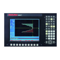
4200T
Anilam 4200T Manuals
Manuals and User Guides for Anilam 4200T. We have
3
Anilam 4200T manuals available for free PDF download: Programming And Operations Manual, Training Manual, Manual
Anilam 4200T Programming And Operations Manual (355 pages)
CNC
Brand:
Anilam
| Category:
Control Systems
| Size: 4 MB
Table of Contents
Table of Contents
3
Introduction
14
Axis Descriptions
15
Part Zero Definition
16
Polar Coordinates
17
Absolute Positioning
18
Incremental Positioning
19
Developing Part Programs
20
CNC Console
22
Keypad
23
Alphanumeric Keys
24
Editing Keys
26
Soft Keys
27
Pop-Up Menus
28
Typeover and Insert Modes
29
Manual Panel
31
Manual Panel Keys
32
Manual Panel Leds
33
Manual Mode Screen
34
Machine Status Display Area Labels
35
Program Area Labels
36
Shutting down the CNC
37
Activating Manual Mode Rapid or Feed
38
Adjusting Rapid Move Speed
39
Setting Absolute Zero
40
Jog Moves
41
Jogging the Machine (in Increments)
42
Using Manual Data Input Mode
43
Operating Handwheels Mounted on the Machine
44
Preparatory Functions: G-Codes
45
Rapid Traverse (G0)
47
Linear Interpolation (G1)
48
Angular Motion Programming Example
49
Circular Interpolation (G2 and G3)
50
Partial Arcs
52
Ellipse (G5)
53
Non-Modal Exact Stop Check (G9)
54
Setting Software Limits (G22)
55
Maximum Spindle Speed (G24)
56
Probe Move (G31)
57
Offsets (Work Coordinate System Select) (G53)
58
Modal Corner Rounding/Chamfering (G59)
60
Cancel Modal Corner Rounding (G60)
62
Contouring Mode (Cutting Mode) (G64)
63
Using Macros (G65, G66, G67)
64
Inch Mode (G70) or MM Mode (G71)
66
Presetting the Axes (G92)
68
Cutting Feedrates in Feed Per Minute (G94)
69
Setting Spindle Speed to Constant Surface Speed (G96)
70
Programming a Z-Axis Turning/Boring Cycle with a Defined Profile (G73)
71
Programming an X-Axis Facing/Boring Cycle with Defined Profile (G74)
74
Programming a Z-Axis Rough Turning or Boring Cycle (G76)
77
Programming an X-Axis Radial (Facing) Roughing Cycle (G77)
79
Programming a Pecking Cycle (G78)
81
Programming a Chip Break Cycle (G79)
82
Programming a Longitudinal Grooving Cycle (G81)
83
Programming a Radial Grooving Cycle (G82)
85
Types of Threading
87
Cutting Longitudinal Threads with Canned Cycles (G83, Uni-Directional)
88
Cutting Longitudinal Threads with Canned Cycles (G84, Bi-Directional)
90
Cutting Radial Threads with Canned Cycles (G85, Uni-Directional)
93
Cutting Radial Threads with Canned Cycles (G86, Bi-Directional)
96
Tapping a Hole with a Canned Cycle (G87)
98
Programming a Boring Cycle (G88)
100
Lathe Tool Probe Cycles (Option)
102
Tool Probe G-Code Cycle Designations
103
Probe Orientation
105
Description of Tool Probe Cycles
107
Activating the Program Editor
112
Edit Soft Keys
114
Editing Shift Soft Keys
115
Deleting a Program Block
116
Going to a Line of the Program Listing
117
Searching the Program Listing for Selected Text
118
Restoring a Block
119
Abbreviating Statements
120
Marking (Highlighting) Programming Blocks
121
Copying Program Blocks
122
Printing a Portion of a Program
123
Numbering (or Re-Numbering) Program Blocks
124
Reading a Program into Another Program
125
Playing Recorded Keystrokes
126
Accessing the most Recently Used Programs
127
Canceling Unsaved Edits
128
Edit Help Menu
132
Edit Help Soft Keys
136
Help Template Menu
137
Help Graphic Screens
139
Using Help Graphic Screens to Enter Program Blocks
141
Available Help Graphic Screens
142
Programming Modal G-Codes in Edit Help
165
Programming LINE Moves in Edit Help
166
Angle Direction for Front and Rear Tool Posts
167
Using Angles to Program Moves
169
Programming MULTIPLE Move Commands in Edit Help
170
Introduction
171
Starting Draw
172
Putting Draw in Hold
173
Draw Parameters
174
Drawing Compensated Moves
175
Setting Grid Size
176
Automatic Draw Restart
177
Starting Draw at a Specific Block
178
Fitting the Display to the Viewing Window
179
Using the Window Zoom
180
Changing the Viewing Area Without Changing the Scale
181
Activating the Tool Page
182
Entering Values in the Tool Page
184
Clearing Tool Information (Delete Row)
185
Setting Tool-Length Offsets
186
Entering Tool Page Tlo's Using the Calibration Function
187
Tool Offset Modification
188
Activating a Tool Number in the Manual Mode
189
Selecting a Tool Location Code
192
Tool Nose Radius Programming Examples
193
Left of Path TNR Program (G41)
194
Right of Path TNR Program (G42)
196
Canceling Tool Nose Radius Compensation (G40)
198
Choosing the Correct TNR Compensation
199
Motion of Tool During TNR Compensation
201
Compensation Around Acute Angles
202
Changing the Numbers of Look Ahead Blocks
203
Setting Wear Offset Adjustment While Running a Program
204
Changing the Program Directory's Display
205
Creating a New Part Program
206
Selecting a Program for Editing and Utilities
207
Logging to Other Drives
208
Marking and Unmarking Programs
209
Deleting Groups of Programs
210
Renaming Programs
211
Formatting Floppy Disks
212
Displaying System Information
213
Copying Programs From/To Unspecified Locations
214
Printing Programs from Unspecified Locations
215
Deleting an Unspecified Program
216
Optimizing Your Hard Disk
217
Maximizing Program Storage Space
218
Running a Program One Step at a Time
219
Toggling between Motion and Single-Step Mode
220
Single-Step Execution of Selected Program Blocks
221
Position Display
222
Holding or Canceling an Auto Run
223
Using Draw While Running Programs
224
Teach Mode
225
Canceling Teach Mode
226
Parts Counter and Program Timer
227
Background Mode
228
Introduction
229
Miscellaneous Functions (M-Codes)
230
Order of Execution
231
C-Axis Jog
232
Activating the SCI Mode
233
SCI Mode Soft Keys
235
Deactivating the SCI Mode
236
Exiting SCI Mode
237
Performing Line Moves (G01)
238
Setting Software Limits (G22)
239
Homing the Machine (G28)
241
Making a Rough Facing Cut (G77)
242
Cutting Threads (G83)
243
Activating Absolute (G90) or Incremental (G91) Mode
244
Setting the Feedrate to Feed Per Revolution (G95)
245
Setting the Spindle Speed to Revolutions Per Minute (G97)
246
Cutting a Taper
247
Cutting a Chamfer
248
Cutting a Radius
249
Activating the Shape Editor
251
Shape Terminology
252
Selecting Editing Tools
253
Line Tools
255
Arc Tools
257
Arc Tools
258
Example #1, Creating a Basic Shape
259
Reversing an Arc's Direction
262
Projecting Line Segments (Restoring Sharp Corners)
263
Deleting a Segment
264
Deactivating and Activating Shapes
265
Point Tools
266
Line Tools
267
Circle Tools
268
Example #2, Creating Construction Geometry and Chaining It into a Shape
269
Chaining Geometry Elements to Create a Shape
275
Viewing a Listing of Geometry Elements
277
Deleting All Geometry Elements
278
Exiting the Shape Editor
279
Managing Shape Files
280
Deleting Shape Files
281
Verifying Shapes
282
Introduction
283
Accessing the Communication Utilities
284
Setting Communication Parameters
285
Parity
286
Testing the Data Link
287
Testing the Link
288
Setting the Transmission and Receiving Display
289
Using Data Control (DC) Codes
290
Block Separator
291
Expressions and Functions
292
System Variables
293
User Variables
294
Read Only Variables
295
Setting Selective Block Skips
296
Contents of Variables
297
Indirect Transfer
298
Storing the Results of Computation
299
Applications of Parametric Programming
300
User Macro (G65, G66, G67)
301
Setting and Passing Parameters
302
Probe Move (G31)
303
Conditional Statements
304
Unconditional: the LOOP Repeat
305
Abbreviating Statements
306
Logical Terms
307
Comparative Terms
308
File Inclusion
309
Sample Parametric Program
310
Passwords
313
Keypad Equivalent Keyboard Keys
314
Exiting the Software
315
Windows Off-Line Software Installation
316
Disabled Features
317
Introduction
318
Sample Program #1
319
Sample Program #2
321
Sample Program #3
323
Sample Program #4
325
Sample Program #5
327
G70 G90 G0 X0 Z0 T0 M43
328
Sample Program #6
329
G96 S400
330
Sample Program #7
331
X4.7 Z0 M3
332
G0 X4.5 Z.1
332
G0 X0 Z0 T0 M9
332
Sample Program #8
333
Sample Program #9
335
M98 P1
336
G0 X0 Z0 T0 M5
336
G1 X1 Z-.1
336
Inch, Absolute, Rapid X Z, Tool
336
Advertisement
Anilam 4200T Manual (48 pages)
CNC Motion Setup/Testing Utility
Brand:
Anilam
| Category:
Test Equipment
| Size: 1 MB
Table of Contents
Table of Contents
3
Introduction
5
Accessing the MST Utility
5
Activating the MST Screen
6
MST Soft Keys
7
Clearing a Prompt Field or Message (F1)
8
Selecting an Axis
8
Entering a Password
8
Checking Axis Resolution (F2)
9
Detecting the Index Pulse (F3)
10
Canceling the Active MDI or Test Command
10
Activating Manual Data Input Mode (MDI)
10
Balancing Motion Control Axes
11
Differential (AC Systems) and Single-Ended (DC Systems) DSP
12
Board
12
DC Systems
13
Servo Drive Test Board
13
Balancing the DSP Board (F6)
14
Balancing Servo Amplifier Outputs (F6)
16
Amplifier Faults
17
Setting the Signal Gain (F7)
21
AC Systems
23
Servo Amplifier Test Board
23
Balancing the DSP Board (F6)
25
ANILAM Amplifier Parameter Files
26
Balancing Servo Amplifier Outputs (F6)
27
Amplifier Faults
31
Miscellaneous Tests (F9)
31
AC and DC Systems
36
Tuning (F8)
36
Saving Final Values
39
Exiting the MST Screen (F10)
39
Setting up and Tuning the C-Axis
40
Anilam 4200T Training Manual (49 pages)
CNC Control
Brand:
Anilam
| Category:
Control Systems
| Size: 0 MB
Advertisement
Advertisement
Related Products
Anilam 4200T CNC
Anilam Wizard 450
Anilam Wizard 450L
Anilam Wizard 411
Anilam 3300M
Anilam 6000
Anilam Wizard 900
Anilam Wizard 900E
Anilam Categories
Control Systems
Controller
Digital readouts
Music Mixer
Media Converter
More Anilam Manuals
Login
Sign In
OR
Sign in with Facebook
Sign in with Google
Upload manual
Upload from disk
Upload from URL