Sign In
Upload
Manuals
Brands
ANDERSON-NEGELE Manuals
Measuring Instruments
IZMSA
ANDERSON-NEGELE IZMSA Manuals
Manuals and User Guides for ANDERSON-NEGELE IZMSA. We have
1
ANDERSON-NEGELE IZMSA manual available for free PDF download: Operating Manual
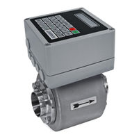
ANDERSON-NEGELE IZMSA Operating Manual (109 pages)
Electro-Inductive Flow Meter
Brand:
ANDERSON-NEGELE
| Category:
Measuring Instruments
| Size: 4 MB
Table of Contents
Table of Contents
3
General Description
9
Preface
9
Construction
9
Function
9
Safety Instructions
9
General Remarks
9
Intended Application
10
Possible Misuse
10
General Safety Instructions
11
Special Safety Instructions and Contrivances
12
Transport
13
General Remarks
13
Special Remarks
13
Separate Design
14
Compact Design
14
Arrangement
15
Conditions for the Transmitter
15
Fitting Position
15
Suggestions for Mounting
17
Inlet and Outlet Pipe Sections
18
Conductivity Conditions
18
Interference Fields
18
Earthing/Grounding Conditions
18
Meter Tube Lining
19
Flow Direction
19
Operating Conditions of the Converter
19
Prevention of Condensation
19
Cable Lengths for the Separated Transmitter Version
20
Installation
20
Installation Instructions for the Transmitter
20
Installation of the Converter
20
Installation of the Electric Supply Voltage
21
Use as Directed
21
Staff Qualification
21
Connection of the Transmitter
22
Brief Instructions
23
Electrical Connection of Peripherals
24
Connection of a Quantity Counter
25
Connection of a Digital Indicator
26
Analog Output
26
Commissioning
27
General Remarks
27
Safety Measures for the Commissioning Work
27
Check List before the Initial Start-Up
28
Basic Settings Upon the Commissioning
29
Structure and Operating Elements
29
LED Array
31
Transmitter Connection in the Separated Version
32
Calibration Switch
32
ABORT Key
33
Calibration Data Storage „Membox
33
Display Unit
33
ZERO Key
34
Converter Without Display Unit
34
Flow Direction
34
Change of the Flow Direction
35
Zero Adjustment ("ZERO Adjust")
35
Metering Operation with Digital and Analog Outputs
37
Digital Outputs IMP1 - IMP3
37
Output "OUT
37
Analog Output
38
Allocation of the Digital Inputs
38
Measurement with Empty Meter Tube
38
Internal "EMPTY Pipe Detection
38
External "EMPTY Pipe Detection
38
Measurement at Low Conductivities
39
Measurement at Pulsating Flow
39
Operation
40
Display Operation in the Metering Mode
40
Main Counter
42
Daily Quantity Counter
42
Totalizing Counter
42
Reset of Error Messages
43
Reset of the Running Counter
43
Parameterization
43
Protection of the Parameters against Unauthorized Modification
44
Function 98
44
CAL" Position
44
How to Modify the Parameters
45
Overview of the Parameters
47
Device Parameters (Menu 02)
49
Output Mode
51
Input/Output Parameters (Menu 03)
53
Display Parameters (Menu 04)
54
Structure of the Data Memory
55
Determination of Parameters and Calibration Data
55
Calibration Factor "M Spe
55
Positive Flow Factor "P Spe
56
Negative Flow Factor "N Spe
56
Dimensioning Factor "M DIM
56
Fine Adaptation by "B Spe
57
Help in Case of Malfunction
57
Error Messages
57
Typical Effects or Possible Malfunctions
59
The Display Shows "Warning 901
59
If Existing Flow Is Not Displayed
59
The Pulse Transmission Is Disturbed Although Flow Is Displayed
60
No Analog Signal Available
60
Strong Fluctuations of Measured Values
61
Reset of Error Messages
61
Displayed Messages
62
List of Possible Key Functions
63
Output Simulation
63
Hardware Test
64
Transmitter Test
65
Insulation Test
65
Symmetry Test
65
Visual Check
66
Maintenance
66
Upkeep
66
Safety Precautions for Maintenance
67
Preventive Maintenance Steps
67
Repairs
68
Sending in the Flow Meter to the Manufacturer
68
Repair Work
69
Replacement of the Fuse for Feeble Currents
69
Replacement of the Main Board
69
Status Upon the Delivery of a Spare Main Board
69
Replacement of the Power Supply Unit
70
Replacement of the Storage Battery
70
Replacement of the Housing Cover
70
Replacement of the Transmitter
70
Spare Parts to be Kept Available on Stock
71
Decommissioning
71
Temporary Decommissioning
71
Final Decommissioning / Disposal
71
Spare Parts
72
Description T0 Version
73
Electrical Connection
73
Intended Use
73
Connecting the Transmitter
73
Connection of a Temperature Sensor Pt 100
74
General Remarks - T0 Version
75
Operating Elements
75
ZERO"-Taste
75
Switching on the Supply Voltage
76
Measuring Mode
76
Operation
76
Zero Position of the Volume Counters
76
Serial Interface
77
RS232 Connection
77
RS232 Parameter
78
Scope of Data Via the Serial Interface
78
Implementation of the Protocol of the Serial Interface
78
Types of Data Blocks
79
Flow Direction
80
Flow in "+" Direction
80
Calibration Parameters (Menu 05)
81
Date/Time (Menu 08)
82
If the Existing Flow Is Not Displayed
82
Considerable Fluctuations of the Measured Value
82
Hardware-Test
83
How to Correct the Temperature Display
83
Structure and Denomination of the Device - Transmitter
86
Transmitter in Separated Design
86
Measuring Ranges and Error Limits
86
Intended Use
86
Dimensions and Weight
87
Transmitter in Separated Design
87
Dimensions of the Process Connections
87
Conditions Required for the Transmitter
90
Parts of Air and Gas
90
Solid Parts
90
Conductivity Conditions
90
Meter Tube Lining
90
Flow Direction
90
Cable Lengths for the Separated Transmitter Version
90
Welding Work
91
Wire End Ferrule
91
Installation
92
Installation Instructions for the Transmitter
92
Connection of the Transmitter in Separated Design
93
Function
93
Connection Scheme for the Separated Design
93
Connection Transmitter
94
Advice for Starting-Up the Flow Tube
95
Membox
96
Measuring Accuracy
96
Visual Check
96
Maintenance
96
Safety Instructions for Maintenance Work
96
Quantity Preselection Functions
96
General Description
96
Electrical Connection
97
Operation
98
Keg Mode of Operation (External Control) ("Preset Mode 1")
100
Manual Drum Selection ("Preset Mode 2")
102
Quantity Preselection Via the Profibus ("Preset Mode 4")
103
Keg Mode of Operation Via the Profibus ("Preset Mode 5")
103
Drum Statistics
105
Quantity Preselection Parameters
106
Functions of the Quantity Preselection Parameters
107
Setting and Optimization of the Preselection Parameter
107
Error Messages
108
Additional Information
109
Advertisement
Advertisement
Related Products
ANDERSON-NEGELE IZMAG
ANDERSON-NEGELE IZMS 025
ANDERSON-NEGELE IZMS 032
ANDERSON-NEGELE IZMS 050
ANDERSON-NEGELE IZMS 065
ANDERSON-NEGELE IZMS 080
ANDERSON-NEGELE IZMS 100
ANDERSON-NEGELE ITM-51R
ANDERSON-NEGELE ILM-4
ANDERSON-NEGELE ILM-4R
ANDERSON-NEGELE Categories
Measuring Instruments
Accessories
Controller
Voice Recorder
Adapter
More ANDERSON-NEGELE Manuals
Login
Sign In
OR
Sign in with Facebook
Sign in with Google
Upload manual
Upload from disk
Upload from URL