Sign In
Upload
Manuals
Brands
ANATEL Manuals
Measuring Instruments
A643
ANATEL A643 Manuals
Manuals and User Guides for ANATEL A643. We have
1
ANATEL A643 manual available for free PDF download: Operator's Manual
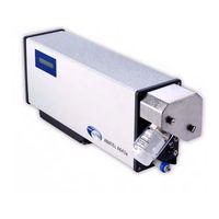
ANATEL A643 Operator's Manual (222 pages)
TOC ANALYZER
Brand:
ANATEL
| Category:
Measuring Instruments
| Size: 15 MB
Table of Contents
Table of Contents
3
1 Introduction
13
Fig 1-1 : the Anatel A643A-P Portable TOC Analyzer
13
The Anatel A643A TOC Analysis System
14
Anatel A643A Analyzer Features
15
Fig 1-2 : A-Net RS-485 Local Area Network
15
Operational Overview
16
Fig 1-3 : Anatel A643A-P TOC Analyzer Components
17
2 Instrument Installation
19
General Information
19
Pre-Installation Procedures
20
Unpacking & Inspection
20
Operational Verification
20
Fig 2-1 : Passive Terminator
21
Fig 2-2 : C80 Logon Screen
21
Software Setup
22
Fig 2-3 : System Time
22
Fig 2-4 : Sensor Setup Selections
22
Fig 2-5 : System Time Submenu
22
Fig 2-6 : System Time Screen
23
Fig 2-7 : Controller Edit Selections
23
Fig 2-8 : Current Day Display
23
Fig 2-9 : Current Time Display
24
Fig 2-10 : Sensor Setup Selections
24
Fig 2-11 : Analyzer Name
24
Fig 2-12 : Analysis Setup Selections
25
Fig 2-13 : Sensor Name Screen
25
Fig 2-14 : Controller Edit Mode
25
Hardware Installation
26
Mounting
26
Fig 2-15 : Change Character
26
Fig 2-16 : Sensor Name Change
26
Fig 2-17 : Controller Mounting Dimensions
27
Fig 2-18 : Anatel A643A-S Mounting Template
28
Plumbing Connections
29
Fig 2-19 : Anatel A643A-P Orientation
29
Fig 2-20 : High-Purity Water System
30
Fig 2-21 : Anatel A643A Analyzer
31
Fig 2-22 : Anatel A643A Water I/O Connections
32
Communications Connections
33
Fig 2-23 : Anatel A643A Analyzer (Bottom View)
34
Power Connections
36
Analyzer Initialization
36
Fig 2-24 : A-Net (Maximum 8 Anatel Analyzers)
36
Fig 2-25 : Manual Menu
37
Fig 2-26 : Modes Menu
37
Fig 2-27 : Special Modes Menu
37
Fig 2-28 : Print Menu
38
Fig 2-29 : Printouts Menu
38
3 Network Installation
39
General Information
39
Software Setup
39
ID to S/N Cross Reference
39
Fig 3-1 : ID to Serial Number Cross-Reference Screen
39
Controller Address
40
Fig 3-2 : Sensor Setup Selections
40
Fig 3-3 : Controller Edit Mode
40
Network Setup
41
Fig 3-4 : Controller Address Screen
41
Fig 3-5 : A-Net Communications Connections
42
Network Connections
43
Fig 3-6 : Sensor NET Port Connections
43
4 C80 Controller Setup
45
General Information
45
C80 Controller
45
Fig 4-1 : C80 Controller Display
45
Operational
46
Contrast Adjustment
46
Fig 4-2 : Contrast Adjustment
47
Fig 4-3 : C80 Setup Selections
47
Fig 4-4 : C80 Setup Submenu
47
Fig 4-5 : C80 Contrast Adjustment Screen
47
View Options
48
The Single Channel
48
Fig 4-6 : View Submenu
48
The Multichannel View
49
Fig 4-7 : Single Channel View
49
Fig 4-8 : the Multichannel View
49
The Channel Display
50
Fig 4-9 : the Channel Display
50
Fig 4-10 : the Checksum Display
50
5 Anatel A643A Setup
51
General Information
51
Factory Defaults
51
Fig 5-1 : Factory Defaults Menu
53
Fig 5-2 : Factory Default Selection
53
Fig 5-3 : Factory Defaults Screen
53
Password Security
54
Fig 5-4 : Set Password Menu
54
Fig 5-5 : Setting Supervisor Password Screen
55
Fig 5-6 : Enter Supervisor ID
55
Fig 5-7 : Enter Supervisor Password
55
Display Units
56
Fig 5-8 : Setting Operator Password Screen
56
Fig 5-9 : Display Units Menu
56
Fig 5-10 : Display Units Menu
57
Fig 5-11 : Display Units Screen
57
Fig 5-12 : Uncompensated Conductivity Display
58
The Auto TOC Mode
59
Fig 5-13 : Purge Printout
59
Fig 5-14 : Auto TOC Mode Selection
59
Fig 5-15 : Analysis Time Line
60
Fig 5-16 : Oxidation State
60
Fig 5-17 : P1-Type Oxidation Curve
61
Fig 5-18 : P2-Type Oxidation Curve
61
Fig 5-19 : P3-Type Oxidation Curve
61
Auto TOC Software Setup
62
Fig 5-20 : Auto TOC Software Setup
62
Fig 5-21 : Sample Time
63
Fig 5-22 : Sample Time Screen
64
Fig 5-23 : Sample Time Displayed
64
Fig 5-24 : Change Sample Time
64
Fig 5-25 : the Cycle Time Screen
65
Fig 5-26 : Cycle Time Displayed
65
Fig 5-27 : Change Cycle Time
66
Fig 5-28 : Sampling Mode
66
Fig 5-29 : Sampling Mode Screen
67
Fig 5-30 : Cycle Modes
68
Fig 5-31 : Cycle Modes Screen
68
Auto TOC Printout
69
Fig 5-32 : Sample TOC Printout
69
Fig 5-33 : Auto TOC Printout
70
Fig 5-34 : TOC Print
70
The Purge Mode
71
Fig 5-35 : TOC Print Format
71
Fig 5-36 : Paper Saver Print Screen
71
Purge Printouts
72
Fig 5-37 : Selecting the Purge Mode
72
Fig 5-38 : Purge Printout
73
Fig 5-39 : Purge Print Outputs
73
Fig 5-40 : Timed Purge Print Screen
74
Fig 5-41 : Timed Purge Print
74
The Manual Mode
75
Fig 5-42 : Paper Saver Print Screen
75
Fig 5-43 : Paper Saver Print
75
Grab Samples
76
Fig 5-44 : Grab Samples
76
Fig 5-45 : Grab Sample Menu
76
Fig 5-46 : Analysis Cycle Results
77
Fig 5-47 : Grab Sample Analysis
77
On-Line Samples
78
Fig 5-48 : Grab Sample Printout
78
Fig 5-49 : On-Line Samples
78
Fig 5-50 : Manual Sample State
78
Fig 5-51 : Sample Time Interval
79
Fig 5-52 : Manual Oxidize State
79
6 Calibration and Validation
81
General Information
81
TOC Calibration
82
Fig 6-1 : TOC Calibration
82
Fig 6-2 : Calibration Standard Criteria
83
Fig 6-3 : Calibration Purge Mode
84
Fig 6-4 : Calibration Mode
84
Fig 6-5 : Remove Instrument Vessel
85
Fig 6-6 : Calibration Data
85
Fig 6-7 : TOC Calibration Results
86
Fig 6-8 : Sample TOC Calibration Printout
86
TOC Validation
87
Fig 6-9 : TOC Validation
87
Fig 6-10 : Validation Standard Criteria
88
Fig 6-11 : Analysis Replicates
89
Fig 6-12 : Blank Average
89
Fig 6-13 : Analysis Results
89
Fig 6-14 : TOC Validation Results
89
Fig 6-15 : Sample Single-Point TOC Validation Printout
90
Fig 6-16 : Sample Three-Point TOC Validation Printout
90
Conductivity Calibration
91
Fig 6-17 : Conductivity Calibration
91
Fig 6-18 : Calibrate Menu
91
Fig 6-19 : Remove Shroud
92
Fig 6-20 : Conductivity Meter Results
92
Fig 6-21 : Remove Resistor
93
Fig 6-22 : Conductivity Calibration Results
94
Fig 6-23 : Sample Conductivity Calibration Printout
94
System Suitability
95
Fig 6-24 : System Suitability
95
Fig 6-25 : Certificate of Analysis Values
96
Fig 6-26 : Certificate of Analysis Displayed
96
Fig 6-27 : Analysis Replicates
97
Fig 6-28 : System Suitability Results
97
Fig 6-29 : Adjust Alarm Limit
98
Fig 6-30 : Sample System Suitability Printout
98
Data History
99
Fig 6-31 : Data History
99
Fig 6-32 : Show TOC Cal
99
Fig 6-33 : Last Accepted
99
Fig 6-34 : Data History Screen
100
Fig 6-35 : Data History Print
100
7 Anatel A643A Alarms
101
General Information
101
Software Setup
101
Alarm Setup
101
Fig 7-1 : Alarm Setup
101
Fig 7-2 : Alarm Setup Menu
102
Fig 7-3 : Sensor Setup Menu
102
Fig 7-4 : Analysis Setup Menu
102
Fig 7-5 : more Setup Menu
102
Fig 7-6 : Alarm Setup Menu
103
Fig 7-7 : Change Alarm Limit
103
Fig 7-8 : TOC Alarm Limit Screen
103
Beeper Setup
104
Fig 7-9 : Alarm Limit Changed
104
Fig 7-10 : Beeper Setup
104
Fig 7-11 : Beeper Setup Menu
104
Alarm Reporting
105
Fig 7-12 : C80 Alarm Beeper Screen
105
Fig 7-13 : Reported Sensor Alarm
105
Uncompensated Conductivity Alarms
106
Fig 7-14 : Alarm Setup
107
Fig 7-15 : Alarm Setup Menu
107
Alarm Acknowledgement
108
Fig 7-16 : Uncompensated Conductivity Alarm
108
Fig 7-17 : Acknowledged Sensor Alarm
109
Fig 7-18 : Alarm Reporting
109
8 Printer Output
111
General Information
111
Hardware Setup
111
Fig 8-1 : External Printer Wiring
112
Software Setup
114
Internal Log
114
Fig 8-2 : Log Setup
115
Fig 8-3 : Log Screen
115
Fig 8-4 : Print Range
116
Fig 8-5 : Sample Log Printout
116
Printouts
117
Fig 8-6 : Log Setup Screen
117
Fig 8-7 : Sensor Print
117
Fig 8-8 : Printouts Screen
118
Fig 8-9 : Setup Printout
119
Fig 8-10 : Factory Printout
119
9 Analog Outputs
121
General Information
121
TOC Output
121
Hardware Setup
121
Fig 9-1 : Current and Voltage Output Wiring
122
Software Setup
123
Fig 9-2 : Analog Setup
123
Fig 9-3 : Setup Menu
123
Fig 9-4 : Sensor Setup Menu
124
Fig 9-5 : Analog Setup
124
Fig 9-6 : DAC Range Menu
124
Fig 9-7 : DAC Range Menu
125
Fig 9-8 : Ma Range Screen
125
Fig 9-9 : DAC Range Menu
126
Fig 9-10 : Zero-Scale TOC Screen
126
Fig 9-11 : Zero-Scale TOC Menu
126
Fig 9-12 : Zero-Scale TOC Data
127
Fig 9-13 : Full-Scale TOC Screen
127
Fig 9-14 : Full-Scale TOC Data
127
Fig 9-15 : DAC Error Output Menu
128
Fig 9-16 : DAC Error Output Screen
128
Optional Conductivity/Resistivity & Temperature Outputs
129
Hardware Setup
129
Fig 9-17 : DAC Calibration Output Screen
129
Fig 9-18 : External DAC Wiring
130
Software Setup
131
Fig 9-19 : External DAC Module Setup
131
Fig 9-20 : Setup Menu
132
Fig 9-21 : DAC Error Output Menu
132
Fig 9-22 : External DAC Module Screen
132
Fig 9-23 : DAC Ma Range Screen
133
Fig 9-24 : DAC Ma Range Menu
133
Fig 9-25 : Conductivity/Resistivity Output Setup
134
Fig 9-26 : DAC Zero-Scale Menu
134
Fig 9-27 : Zero-Scale Uncompensated Conductivity Display
135
Fig 9-28 : Zero-Scale TOC Data
135
Fig 9-29 : Full-Scale Uncompensated Conductivity Display
135
Fig 9-30 : Full-Scale TOC Data
136
Fig 9-31 : DAC Zero-Scale Menu
136
Fig 9-32 : Zero-Scale Temperature Screen
136
Fig 9-33 : Zero-Scale Temp Data
137
Fig 9-34 : Full-Scale Temperature Screen
137
Fig 9-35 : Full-Scale Temp Data
137
10 Digital Inputs & Outputs
139
General Information
139
Digital Inputs
140
10.2.1 Hardware Setup
140
10.2.2 Software Setup
141
Fig 10-1 : Typical Digital Input Wiring
141
Fig 10-2 : Software Setup
141
Digital Outputs
142
Fig 10-3 : Manual Submenu
142
Fig 10-4 : Modes Menu
142
Fig 10-5 : Special Modes Screen
142
10.3.1 Hardware Setup
143
Fig 10-6 : Typical Digital Output Wiring
143
11 12 VDC Bias Output
145
General Information
145
Hardware Setup
145
Fig 11-1 : Bias Connections
146
12 Serial Communications
147
General Information
147
Hardware Setup
147
Fig 12-1 : Serial Wiring
148
Anatel A643A Command Set
149
Mode Set Commands
149
12.3.2 Parameter Set Commands
150
12.3.3 Data Read Commands
151
12.3.4 Log Commands
152
12.3.5 Data History Commands
153
13 Anatel A643A Maintenance
155
General Information
155
Self-Cleaning Mode
155
Fig 13-1 : Manual Menu
156
Fig 13-2 : Special Modes Menu
156
Fig 13-3 : Selecting the Self-Clean Mode
156
Preparatory Maintenance Procedures
157
UV Lamp Maintenance
158
Fig 13-4 : Location of Hex Bolts
158
Fig 13-5 : Anatel A643A UV Lamp Assembly
158
13.4.1 UV Detect Technology
160
13.4.2 Replacing the UV Lamp
161
Fig 13-6 : Anatel A643A UV Lamp Replacement Diagram
161
Fig 13-7 : Loosening the UV Lamp Bracket
162
Fig 13-8 : Pulling the UV Lamp Connector Plug
162
Fig 13-9 : Prior UV Lamp Assembly Design with Adapter Plugs
163
Fig 13-10 : Inserting the New UV Lamp Assembly
163
Fig 13-11 : Aligning the Arrow with the Bracket Screw
163
Fig 13-12 : Inserting the UV Lamp Connector
164
Fig 13-13 : Lamp Setup
165
Fig 13-14 : Resetting the Lamp Counter
165
Air Filter Cleaning
166
Lithium Battery Replacement
166
Fig 13-15 : Anatel A643A Air Filters
166
Fig 13-16 : 26-Pin Connectors
167
Fig 13-17 : Lithium Battery
167
Fig 13-18 : Replace Battery
168
Fig 13-19 : Pin #1
169
Inlet Filter Replacement
170
Fig 13-20 : Inline Filter Assembly
171
Fig 13-21 : Collar Position
171
Printer Paper Replacement
172
Fig 13-22 : Printer Paper Roll
173
14 Troubleshooting
175
General Information
175
Alarm Codes
175
Troubleshooting
178
Fig 14-1 : Failure Identified
179
14.3.1 Draining the Instrument
181
Sensor Diagnostics
182
Fig 14-2 : Sensor Diagnostics
182
Fig 14-3 : Diagnostics Menu
182
14.4.1 Electronics Tests
183
Fig 14-4 : Electronics Diagnostic Screen
183
Cell Tests184
184
Fig 14-5 : Cell Diagnostics Screen
184
Fig 14-6 : Diagnostics Menu
184
14.4.3 I/O Tests
185
Fig 14-7 : I/O Diagnostics Screen
186
Fig 14-8 : RS-232 Loopback Wiring
186
Fig 14-9 : Digital I/O Loopback Wiring
186
Fig 14-10 : DAC Output Test Screen
187
Appendix A:service Procedures
189
Return Procedures
189
Technical Support Information
189
Appendix B:specifications and Accessories
191
Performance Specifications
191
Anatel A643A-S Analyzer
193
Fig B-1 : Anatel A643A-S TOC Analyzer
193
B.1.1 Anatel A643A–S Analyzer
193
Anatel A643A-P Analyzer
194
Fig B-2 : Anatel A643A-P TOC Analyzer
194
B.1.2 Anatel A643A–P Analyzer
194
B.1.3 C80 Controller
195
C80 Controller
195
Fig B-3 : C80 Controller
196
Accessories
197
Thermal Printer
197
Fig B-4 : Thermal Printer
197
B.2.1 Thermal Printer
197
Appendix C:certifications
199
Overview
199
Declaration of Conformity
200
Appendix D:anatel A643A Menu Flowcharts
201
Appendix E:material Data Safety Sheets
205
Appendix F:glossary
211
Annex
213
User Notes
219
Advertisement
Advertisement
Related Products
ANATEL A643a
ANATEL AM111GMGN
ANATEL Novus RHT-Air
ANATEL Categories
Measuring Instruments
Remote Control
Wireless Access Point
PCI Card
Cash Counter
More ANATEL Manuals
Login
Sign In
OR
Sign in with Facebook
Sign in with Google
Upload manual
Upload from disk
Upload from URL