Sign In
Upload
Manuals
Brands
ANALOX Manuals
Measuring Instruments
ACG+
User Manuals: ANALOX ACG+ Gas Analyzer
Manuals and User Guides for ANALOX ACG+ Gas Analyzer. We have
3
ANALOX ACG+ Gas Analyzer manuals available for free PDF download: User Manual, Service & Troubleshooting Manual
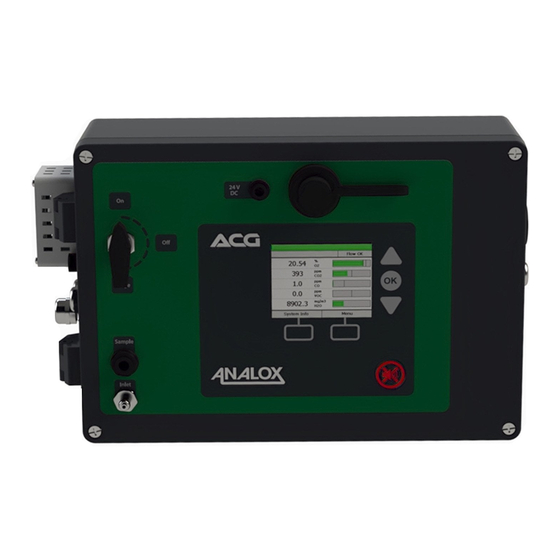
ANALOX ACG+ User Manual (102 pages)
Brand:
ANALOX
| Category:
Measuring Instruments
| Size: 4 MB
Table of Contents
Table of Contents
3
Contents Checklist
8
Standard Contents
8
Optional Accessories
8
Safety Information
9
Capabilities to Test Gases against the en 12021:2014 Standard
9
Electrochemical Sensors (Oxygen and Carbon Monoxide)
9
Table 1 Electrochemical Sensor First Aid Procedures
9
PID Lamp Cleaning Kit
10
Inlet Pressure & Flow
10
Introduction
11
ACG+ Overview
11
Figure 1 ACG+ Overview
11
Installation Details
13
Mechanical Overview
13
Figure 2 ACG+ Mechanical Overview
13
Gas Sample Connection (both Fixed and Portable Versions)
14
Installation (Portable)
15
Figure 3 Typical ACG+ Portable Installation
15
Installation (Fixed)
17
Figure 4 Typical ACG+ Fixed Installation
17
Figure 5 Connector Locations
18
Table 2 Connector J17 Pin Assignments
18
Figure 6 ACG+ Power
19
Table 3 Connector J3 Pin Assignments
19
Safety Interlock Relay (ACG+ Fixed)
20
Figure 7 Typical Interlock Relay Wiring
20
Safety Interlock Override Key-Switch (ACG+ Fixed)
21
Table 4 Relay and 24V Output Operation under Fault and Alarm Conditions
21
Switched 24V DC Outputs (ACG+ Fixed)
22
Figure 8 Typical Use of Switched 24V Outputs
22
Operating Instructions
23
Start-Up
23
Figure 9 Start-Up Splash Screen
23
Controls
24
Figure 10 ACG+ Front Panel
24
Inlet/Purge Valve
25
Display
26
Figure 11 Main Display Overview
26
Menu
27
Figure 12 System Status Indicator
27
Figure 13 the Main Menu
27
Adjusting the Backlight
28
Figure 14 the Backlight Sub-Menu
28
Power Sub-Menu
29
System Flow
29
Figure 15 Power Sub-Menu
29
Sensor Readings
30
Table 5 Sensor Status Icons
30
Figure 16 Example of a Sensor that Is in a Warm-Up State
31
Figure 17 Sensor Bar Graph Indicator
31
Figure 18 Degraded State Sensor Bar Graph Indicator
31
Figure 19 out of Display Range Bar Graph Indicators
31
Alarms
32
Figure 20 Sensor in Fault Bar Graph Indicator
32
Figure 21 a Low-Going Alarm that Has Been Triggered
32
Figure 22 Mute Button
32
Clearing Alarms and Hysteresis
33
Figure 23 Hysteresis Band on a High Going Oxygen Alarm
33
Table 6 Scaled Hysteresis Values
33
Figure 24 Selecting a CO
35
Figure 25 Example of Alarm Set-Point Adjustment
36
Calibration Adjustment
37
Table 7 Recommended Calibration Gas Concentrations
37
Figure 26 Flow Regulator Fitted to Calibration Bottle
39
Figure 27 Connecting Calibration Fitting to ACG+ Calibration Port
39
Figure 28 Calibration Adjustment Screen Showing High Calibration Bottle
40
Figure 29 Calibration Adjustment Results - CO Sensor Failed to Adjust
41
Figure 30 Excluding the VOC Sensor from the Calibration Adjustment
42
Figure 31 Adjusting the CO
43
Figure 32 Calibration Adjustment Reminder
43
Viewing Device Information
44
Viewing Sensor Information
44
Figure 33 Device Information Screen
44
Figure 34 Sensor Information Screen for O
44
Data-Logging
45
Table 8 Data-Log Formatting Example
45
Figure 35 Data-Log Download Screen
46
Figure 36 Data-Log Download in Progress
46
Sensor Replacement Reminder
48
Figure 37 Sensor Change Reminder
48
Timed Sample Draw
49
Figure 38 Sensor Replacement Reset Confirmation Screen
49
Figure 39 a Dräger Impactor Attached to the Outlet Port for Oil Mist Testing
51
Figure 40 Timed Sample Setup
52
Figure 41 Timed Sample Progress
52
Setting the Date and Time
53
Figure 42 Date and Time Adjustment Screen
53
Configuration
54
Software Installation
54
Making a Connection
57
Figure 43 ACG+ Software Without Device Connected
57
Figure 44 Connecting a USB Cable to an ACG
57
Changing Options
59
Figure 45 ACG Software with Device Connected Showing General Options
59
Downloading Data-Logs
60
Figure 46 the Data Logs Available on a Connected ACG
60
Setting the Time
61
Figure 47 Downloading Data Logs from an ACG
61
Figure 48 Setting the Date and Time on an ACG
61
Networking
62
Overview
62
Connection
62
Transmission Method
62
Setting the ACG Static IP Address
63
Retrieving Data Using TCP/IP Requests
63
Retrieving Data Using UDP
64
Datagram Structure
64
Troubleshooting
70
System Faults
70
Figure 49 System Showing a Fault Condition
70
Table 9 List of System Faults and Possible Solutions
71
Table 10 List of Sensor Faults and Possible Solutions
72
Recommended Spares and Accessories
75
Table 11 List of Spares
75
Table 12 List of Accessories
76
Service Requirements
77
Table 13 6 Monthly Service for ACG
77
Table 14 12 Monthly Service for ACG
77
Table 15 24 Monthly Service for ACG
77
Maintenance Requirements
78
Sensor & Filter Replacement
78
Table 16 Maintenance Schedule of ACG+ Components
78
Filter Replacement
91
Service Requirements
92
Table 17 Service Schedule of ACG+ Components
92
Specifications
99
Instrument Specification
99
Sensor Specification
100
Declaration of Conformity
101
Document Ref: P0149-801-22 July 2022
102
Declaration of Conformity
102
Advertisement
ANALOX ACG+ User Manual (96 pages)
Brand:
ANALOX
| Category:
Measuring Instruments
| Size: 2 MB
Table of Contents
Table of Contents
3
1 Contents Checklist
5
Standard Contents
5
Optional Accessories
5
2 Safety Information
6
Capabilities to Test Gases against the en 12021:2014 Standard
6
Electrochemical Sensors (Oxygen and Carbon Monoxide)
6
Table 1 Electrochemical Sensor First Aid Procedures
6
PID Lamp Cleaning Kit
7
Inlet Pressure & Flow
7
3 Introduction
8
ACG+ Overview
8
4 Installation Details
9
Mechanical Overview
9
Gas Sample Connection (both Fixed and Portable Versions)
9
Installation (Portable)
11
Installation (Fixed)
13
Table 2 Connector J17 Pin Assignments
14
Table 3 Connector J3 Pin Assignments
14
Safety Interlock Relay (ACG+ Fixed)
15
Safety Interlock Override Key-Switch (ACG+ Fixed)
16
Table 4 Relay and 24V Output Operation under Fault and Alarm Conditions
16
Switched 24V DC Outputs (ACG+ Fixed)
17
5 Operating Instructions
18
Start-Up
18
Controls
19
Inlet/Purge Valve
20
Display
20
Menu
21
Adjusting the Backlight
22
Power Sub-Menu
22
System Flow
23
Sensor Readings
24
Table 5 Sensor Status Icons
24
Alarms
26
Table 6 Scaled Hysteresis Values
27
Calibration Adjustment
29
Table 7 Recommended Calibration Gas Concentrations
29
Viewing Device Information
34
Viewing Sensor Information
34
Data-Logging
35
Table 8 Data-Log Formatting Example
35
Sensor Replacement Reminder
37
Timed Sample Draw
39
Setting the Date and Time
41
6 Configuration
42
Software Installation
42
Making a Connection
57
Changing Options
58
Downloading Data-Logs
59
Setting the Time
59
7 Networking
61
Overview
61
Connection
61
Transmission Method
61
Setting the ACG Static IP Address
62
Retrieving Data Using TCP/IP Requests
63
Retrieving Data Using UDP
63
Datagram Structure
64
8 Troubleshooting
70
System Faults
70
Table 9 List of System Faults and Possible Solutions
71
Table 10 List of Sensor Faults and Possible Solutions
72
9 Recommended Spares and Accessories
74
Table 11 List of Spares
74
Table 12 List of Accessories
75
10 Maintenance Requirements
76
Sensor & Filter Replacement
76
Table 13 Maintenance Schedule of ACG+ Components
76
Filter Replacement
84
Service Requirements
85
Table 14 Service Schedule of ACG+ Components
85
11 Specifications
93
Instrument Specification
93
Sensor Specification
93
12 Declaration of Conformity
95
Document Ref: P0149-801-09 January 2018
95
ANALOX ACG+ Service & Troubleshooting Manual (37 pages)
Brand:
ANALOX
| Category:
Measuring Instruments
| Size: 2 MB
Table of Contents
Table of Contents
3
Safety Information
6
Electrochemical Sensors (Oxygen and Carbon Monoxide)
6
Table 1 Electromechanical Sensor First Aid Procedure
6
PID Lamp Cleaning Kit
7
Introduction
8
Recommended Spares and Accessories
9
Table 2 List of Spares
9
Table 3 List of Accessories
10
Service Requirements
11
Table 4 6 Monthly Service for ACG
11
Table 5 12 Monthly Service for ACG
11
Table 6 24 Monthly Service for ACG
11
Maintenance
12
Sensor & Filter Replacement
12
Table 7 Maintenance Schedule of ACG+ Components
12
Oxygen Cell Replacement
13
Carbon Monoxide Cell Replacement
16
Replacing the CO Cell PCB (MEC-233B)
18
VOC Maintenance
22
Water Vapour Sensor Replacement
25
Filter Replacement
26
Activated Charcoal Filter Replacement
26
Particulate Filter Replacement
27
Service Requirements
27
Table 8 Service Schedule of ACG+ Components
27
Replacing the Flow Adaptor Orings
28
Replacing the PID Cell
28
Replacing the PID Cell PCB (MEC-233C)
30
Faq's (most Common Solutions)
35
Recommended Calibration Gas Concentrations
35
Maintenance Schedule of ACG+ Components
35
Sensor Range Fault
35
VOC Sensor Cannot Calibrate
36
Comms
36
COSHH Regulations
37
Heliox/Trimix Mixes
37
Nitrox Gas Mixes
37
Advertisement
Advertisement
Related Products
ANALOX ADM
ANALOX ATA Pro
ANALOX ATAPROAYYA
ANALOX aspida
ANALOX Ax60
ANALOX Ax 50
ANALOX Ax60+ Multi-Gas
ANALOX ADM Aspida
ANALOX A50
ANALOX APM
ANALOX Categories
Measuring Instruments
Security Sensors
Analytical Instruments
Accessories
Gas Detectors
More ANALOX Manuals
Login
Sign In
OR
Sign in with Facebook
Sign in with Google
Upload manual
Upload from disk
Upload from URL