Sign In
Upload
Manuals
Brands
Ametek Manuals
Measuring Instruments
Thermox WDG-1200 Insitu
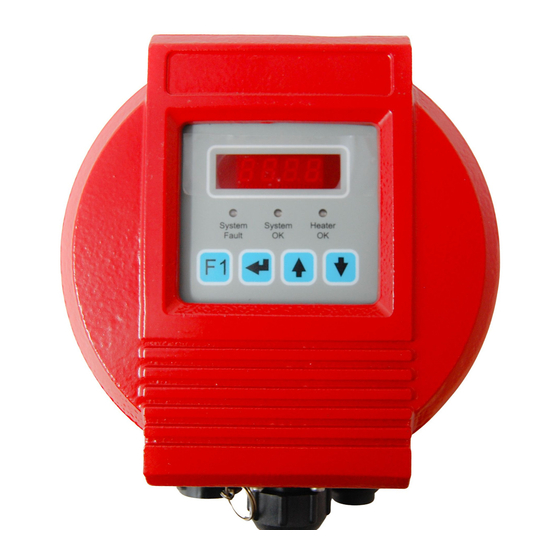
Ametek Thermox WDG-1200 Insitu Analyzer Manuals
Manuals and User Guides for Ametek Thermox WDG-1200 Insitu Analyzer. We have
1
Ametek Thermox WDG-1200 Insitu Analyzer manual available for free PDF download: User Manual
Ametek Thermox WDG-1200 Insitu User Manual (100 pages)
Brand:
Ametek
| Category:
Measuring Instruments
| Size: 3.73 MB
Table of Contents
Offices
2
Table of Contents
3
Electrical Safety
6
Grounding
6
Safety Notes
6
CHAPTER 1 Overview
10
System Features
10
Sensor
11
Problems to Avoid
13
Technical Support
14
CHAPTER 2 Specifications
16
WDG 1200/1210/Insitu Probe
16
CHAPTER 3 Installation and Start-Up
20
Unpacking
20
Mechanical Installation
21
Location
21
Unpacking the Shipping Protection
22
Fitting a Filter or Shield to the Probe
23
Mounting the Sensor
24
Mounting the Controller (WDG-1210 Insitu Only)
25
Mounting Guidelines
26
Installing the Controller
27
Mounting the Control Unit
27
Calibration Setup
28
Required Calibration Gases and Tubing
28
Calibration Inlet
28
Electrical Connections
29
Mains Power Supply
29
Remote Calibration Unit (Optional)
29
Optional Signal Connections
30
Plug Plate Connector Designation - WDG-1200 Insitu
30
Plug Plate Connector Designation - WDG-1210 Insitu
31
System Cables
32
Recommendations for Laying Cable
32
Cable Preparation
32
Cable Recommendations - WDG-1200 Insitu
33
Cable Recommendations - WDG-1210 Insitu
33
Pin Designations - 1200/1210 Insitu
34
Probe Connections - WDG-1210 Insitu Only
37
Grounding
38
Assembly of Connector Plugs
39
Crimped Connector Assembly Procedure
39
Mains Power Supply Plug
41
Mains Connector Assembly Procedure
41
Fitting of Plug Connectors
41
Pre-Operational Checks - Final Checks
42
CHAPTER 4 User Interface and Calibration
43
Control Panel
43
Abbreviations Used on the Control Panel
44
Using the Probe for the First Time
45
Warm up Procedure
45
Operational Structure
46
Probe Display Settings
47
Operational Structure Diagram
47
Calibration Screens
48
Calibration Menu
48
Alarm Screen
52
Analog Outputs Screens
53
Analog Outputs Menu
53
Diagnostics Screens
55
Diagnostics Menu
55
System Configuration Screens
57
System Configuration Menu
57
Output Setup
59
System Outputs
59
Analog Outputs Menu
60
Analog Output Settings
61
Modbus Interface
63
Serial Data Bus Configuration
63
Slave Address and Floating Point Forms
63
Function Codes Supported
63
Exception Codes
63
Register Numbers
64
Data Types
64
Registers Numbers for Instrument Readings
64
Command Register
64
Maintenance Status Register
64
Modbus RS485 Interface
65
Full Register
66
Zero and Span Calibration
68
Access to Calibration Menu from Menu Spine
68
Configuration
70
Automatic Calibration
71
Manual Calibration
72
CHAPTER 5 Maintenance and Troubleshooting
74
Fault Identification Numbers
76
Fault Description
77
Bench Testing
80
In-Situ Probe Testing and Checking
81
Maintenance
85
Routine Maintenance Schedule
85
CHAPTER 6 Service and Parts
87
Inner Probe Assembly Removal
88
Process under Pressure
89
Cell Replacement
90
Removing the Cell
90
Fitting the New Cell
92
Heater/Thermocouple Replacement
96
Removing Heater (See Figure 6-3)
96
Replacing Heater
96
Spare Parts
97
APPENDIX A Drawings and Custom Instructions
99
Advertisement
Advertisement
Related Products
Ametek Thermox WDG-V
Ametek Thermox WDG-VC
Ametek Thermox WDG-VCM
Ametek Thermox WDG-VRM
Ametek Thermox WDG-V UOP
Ametek Thermox WDG-1210 Insitu
Ametek Thermox Series 2000 WDG-IV
Ametek Thermox Series 2000 WDG-IVC
Ametek Thermox Series 2000 WDG-IVCM
Ametek TRACE ANALYTICAL ta7000F-He
Ametek Categories
Measuring Instruments
Test Equipment
Power Supply
Controller
Laboratory Equipment
More Ametek Manuals
Login
Sign In
OR
Sign in with Facebook
Sign in with Google
Upload manual
Upload from disk
Upload from URL