Sign In
Upload
Manuals
Brands
Ametek Manuals
Controller
dunkenmotoren BGE 6060 A
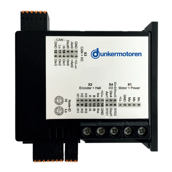
Ametek dunkenmotoren BGE 6060 A Manuals
Manuals and User Guides for Ametek dunkenmotoren BGE 6060 A. We have
1
Ametek dunkenmotoren BGE 6060 A manual available for free PDF download: Translation Of The Original Function And Connection Manual
Ametek dunkenmotoren BGE 6060 A Translation Of The Original Function And Connection Manual (68 pages)
Brand:
Ametek
| Category:
Controller
| Size: 5.6 MB
Table of Contents
Table of Contents
2
About this Document
6
Über dieses Dokument
6
General Description
7
Series
7
Allgemeine Beschreibung
7
Baureihe
7
Explanation of Terms Used
8
Begriffserklärung
8
Proper Use
9
Standards and Guidelines
9
Bestimmungsgemäße Verwendung
9
Zertifikate/ Konformitäten
9
Safety Instructions
10
Sicherheitshinweise
10
Technical Data, Accessories
11
General Performance Data
11
Technische Daten, Zubehör
11
Allgemeine Leistungsdaten
11
General Features
12
Allgemeine Eigenschaften
12
Current Characteristics
13
Stromkennlinien
13
Dimensions
14
Starter Kit (Accessory)
14
Maßzeichnung
14
Starter Kit (Zubehör)
14
Protective Functions
15
Solid State Short Circuit Protection
15
Motor Overload Protection
15
Branch Circuit Protection
15
Field Wiring Terminals
15
Schutzfunktionen
15
Halbleiterkurzschlussschutz
15
Motorüberlastungsschutz
15
Schutz des Abzweigstromkreises
15
Feldverdrahtungsklemmen
15
Types of Operation
16
Slave in Canopen Networks
16
Betriebsarten
16
Slave in Canopen Netzwerken
16
Stand-Alone Operation at Stored Running
17
Profile
17
Stand-Alone Betrieb mit Gespeichertem
17
Fahrprofil
17
Installation
18
Terminal Assignment
19
Anschlussbelegung
19
Power Supply and Motor Connections
20
Versorgungsspannung und Motoranschluss
20
Inputs and Outputs
21
Hallsensoren/Encoder & Analoge und Digi- Tale Ein- und Ausgänge
21
EMC-Compliant Installation
22
EMV-Gerechte Installation
22
Connection Brushless Motor
23
Connection Brushed Motor
23
Anschluss Bürstenloser Motor
23
Anschluss Bürstenbehafteter Motor
23
Connection Hall Sensors
24
Anschluss Hallsensoren
24
Connection Encoder
24
Anschluss Encoder
24
Connection Power Supply
25
Grounding
25
Connection Electronics
25
Controller Enabling (STO)
25
Anschluss Spannungsversorgung
25
Erdung
25
Anschluss Elektronik
25
Reglerfreigabe (STO)
25
Connection CAN Interface
26
Heat Sink Mounting
26
Anschluss CAN Schnittstelle
26
Kühlkörperanbindung
26
Block Diagram
27
Blockschaltbild
27
Digital Inputs
28
Digital Outputs
28
Digitale Eingänge
28
Digitale Ausgänge
28
Analog Inputs
29
Inputs for Hall Sensors
29
Inputs for Encoders
29
Analoge Eingänge
29
Eingänge für Hallsensoren
29
Eingänge für Encoder
29
Auxiliary Power Supply
30
Input/Putput Ratings
30
Hilfsspannungen
30
Eingangs- und Ausgangswerte
30
Status Leds
31
Maintenance & Service & Support
32
Maintenance, Taking out of Service and Dis- Posal
32
Service & Support
32
Declaration of Conformity
32
Wartung & Service & Support
32
Wartung, Außerbetriebsetzung und Entsor- Gung
32
Konformitätserklärung
32
Commissioning
33
Stand Alone Operation
33
System Requirements
33
Installation of Software Drive Assistant
33
Inbetriebnahme
33
Stand Alone Betrieb
33
Systemvoraussetzungen
33
Installation Software Drive Assistant
33
Description of Main Window
34
Project Window
34
Beschreibung des Hauptfensters
34
Projektfenster
34
Short Description of PI Modules
35
PI 100 Positioning Module „Standard
35
Kurzbeschreibung PI Module
35
PI 110 Positioning Module „Stepper
36
PI 120 Positioning Module „Left-Right
37
PI 130 Positioning Module „Modulo
38
PI 140 Positioning Module
39
Complete Positioning Command
39
PI 150 Positioning Module
40
Positioning by Event
40
PI 200 Velocity Module
41
Velocity Mode Standard
41
PI 201 Velocity Module
42
Velocity Mode Multi
42
PI 200 Velocity Module
42
PI 300 Current Module
43
Current Mode Standard
43
PI 301 Current Module
44
Current Mode Multi
44
Slave in Canopen
45
Hardware Controller
45
Hardware Regler
45
Mplc Introduction
46
Documentation
46
Mplc Einführung
46
Dokumentation
46
Mplc System Requirements
47
Installation of the Software Mplc
47
Installation CAN-USB Adapter
47
Mplc Systemvoraussetzungen
47
Installation der Software Mplc
47
Mplc Control Center
48
Python Script
49
CAN Monitor
52
Configuration
54
Konfiguration
54
Objects
56
Objects / SDO-Variable
56
Objekte
56
Objekt- / SDO-Variable
56
Set up CAN Objects
58
Anlegen von CAN-Objekten
58
Set up CAN Variables
59
Anlegen von CAN-Variablen
59
Transmit / Receive
61
Recording
61
Senden / Empfangen
61
Aufzeichnen
61
CAN Master of Other Manufacturers
63
CAN-Master anderer Hersteller
63
Communication Settings
64
Kommunikationseinstellungen
64
Standard Variant - LMT Services
64
Standardvariante -LMT Dienste
64
Manufacturer Specific Variant
65
Herstellerspezifische Variante
65
Test Programs and Other Assistance
66
Testprogramme und Weitere Hilfsmittel
66
Advertisement
Advertisement
Related Products
Ametek DCPA1 Series
Ametek DCPA1-2415
Ametek DCPA1-2425
Ametek DPA1-4830
Ametek DPA1-6030
Ametek DPA1-1230
Ametek DPA1-1250
Ametek DPA1-1215
Ametek DPA1-4850
Ametek DPA1-2450
Ametek Categories
Measuring Instruments
Test Equipment
Power Supply
Controller
Laboratory Equipment
More Ametek Manuals
Login
Sign In
OR
Sign in with Facebook
Sign in with Google
Upload manual
Upload from disk
Upload from URL