Sign In
Upload
Manuals
Brands
American Augers Manuals
Drill
DD-440
American Augers DD-440 Manuals
Manuals and User Guides for American Augers DD-440. We have
1
American Augers DD-440 manual available for free PDF download: Operation & Safety Manual
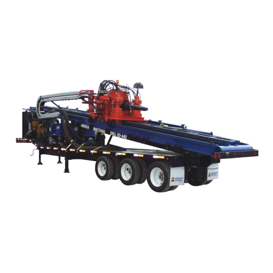
American Augers DD-440 Operation & Safety Manual (94 pages)
Trailer Mounted Directional Drill
Brand:
American Augers
| Category:
Drill
| Size: 13 MB
Table of Contents
Table of Contents
3
1 General Information
10
Use and Maintenance Manual
10
Data of Manual
10
Contents of Manual
10
Who Should Use this Manual
10
Ownership of Information
10
Manufacturer Identification Data
10
Machine Identification Data
11
Declaration of Ec Conformity
11
General Information on Safety
11
Safety Standard
11
Qualification of Personnel
12
Use of Personal Protective Equipment
12
Dangerous Zones-Safe Distances
12
Jobsite Safety
13
Safety Plan and Checklist
13
Responsible Personnel
14
Hazards
14
Verify Utility Locates
15
Traffic Control (Pedestrian and Vehicle)
16
Safe Practices, Safety Equipment
16
Response to Events
17
Conclusion
17
References
18
Uses Allowed
18
Features of the Soil to be Drilled
18
Features of Transport
18
Machine Handling Procedures
18
Uses Not Allowed
19
Warranty
19
General Conditions
19
Limitations of Warranty
19
Limited Warranty Certificate
19
Request for Service Support
20
Warranty and Service for Caterpillar Engine
20
Service Agreement
20
Conventions
20
Conventions of Terminology
20
Typographic Conventions
20
2 Description
20
Parts of the Machine
20
Description of the Directional Drill
20
Truck Trailer
20
Mud
21
Mud Plant
21
Tie down System
21
Drill Pipe
21
Es!Lok
21
Zap Alert
21
Driller's Console
21
Purpose of the Machine
21
Structure
21
Technical Specifications
22
General Features (DD-440)
22
Diesel Engine
22
Electric System
22
Performance as Supplied
22
Vibration
22
Noise
22
Responsibility
22
3 Storage and Transport
22
Storage
22
Storage Site Environment
23
Procedures of Storage
23
Transport
23
Preliminary Operations for Transportation of the Machine
23
Procedures of Positioning
23
Transportation
24
Preparing the Machine for Transportation
24
Lifting the Machine
24
Lifting
24
4 Use
25
Working Site Physical Features
25
Site Preparation
25
Minimum Space Required
25
Ground Leveling
25
Type of Ground
25
Lighting
26
Operating Temperature
26
Relative Humidity Allowed
26
Maximum Altitude
26
Atmospheric Conditions
26
Special Requirements for Using this Machine
26
Increased Need for Support Equipment
26
Increased Crew Size - Drill Side
27
Increased Crew Size - Exit Side
27
Function of the Machine
27
Normal Operation
28
Dangerous Zones-Safe Distances
28
Qualification of the Operator
29
Position of the Operator
29
Controls and Instruments
29
Controls
29
Instruments and Controls (List)
30
Es!Lok® Lockout System
31
Zap Alert
31
Operation
31
Starting the Engine
31
Operating with One Engine
32
Movement of the Machine
32
Set-Up
32
Position the Drill
32
Lower Trailer Landing Gear
32
Position the Driller's Console
32
Install Handrails on the Walkway
32
Lower Support Jacks
32
Install Wrenches on Drill Frame
32
Install Front Foot
32
Anchor the Machine
33
Excavate the Entry Pit
33
Connect the Control Console
33
Drilling Process
33
Deep Crossings - the Setup
34
Deep Crossings - Steering System
34
Deep Crossings - Drilling Method
34
Shallow Crossings - the Process
35
Application of Drilling Fluid to Horizontal Boring
35
Drilling Fluid - the Process
36
Calculation of Volume of Fluid to Volume of Soil
36
Fluid Disposal
36
Water Quality
37
Mud Mixing
37
Adding and Removing Pipe
37
Adding Pipe (First Section with Walkover Location)
37
Adding Pipe (First Section with Wireline Location)
38
Using a Mud Motor
38
The Rotary Brake
39
The Carriage Brake
39
Other Controls
39
Installing a Wireline Guidance Instrument
40
Adding Pipe (Additional Sections)
41
Setting Carriage Rotary Speed
42
Removing Pipe
42
Calculating Rotary Torque Force
43
Calculating Thrust and Pull Back Force
43
Start of the Drilling Operation
44
End of Drilling Operations
44
Start of the Pullback Operations
44
End of Pullback Operations
45
Removing the Tie down Stakes
45
Removal of Anchors
45
Clean up
45
Switching off the Engine
45
Emergency Stop
46
Rotary Carriage Disable
46
Start after an Emergency Stop
46
Checks During Operation
46
Normal Operating Ranges of Instruments
46
Es!Lok® Lockout
46
Start after Use of Es!Lok
47
Use of Zap Alert
47
Start after Use of Zap Alert
47
Operation under Ambient Temperatures between -40°C & -15°C [-40°F to +5°F]
47
Pre-Heating Devices
47
STARTING the ENGINE (with the Machine Kept Warm through Pre-Heaters)
48
STARTING the ENGINE (in Case the Pre-Heaters Are Not Connected While Stopped)
48
Protecting the Fluid Course from Freezing
48
Inspection of Trailer before Moving
48
5 Maintenance
49
Dangerous Zones-Safe Distances
49
Ordinary, Periodical, and Preventive Maintenance
49
Qualification of the Technician
49
Frequency of Inspections
49
Scheduled Inspection and Maintenance
50
Maintenance Schedules of DD-440 Directional Drills
50
Emergency Stop
51
Greasing
51
Engine Oil
51
Engine Coolant
51
Air Filters
51
Fuel
51
Hydraulic Oil Circuit
51
Gearboxes and Pump Drive
52
Welding
53
Radiator
53
Hydraulic Piston Rods
53
Cleaning
53
Other Checks and Maintenance (50 Hours)
53
Bolts and Nuts
53
Pipes and Hoses
53
Leaks
54
Cooling System
55
Clogged Oil Filter
56
Figure 1 Declaration of EC Conformity
58
Figure 2 Limited Warranty Certification
59
Figure 3 Exit Pit Warning
60
Figure 4 Pipe Wrench Warning
60
Figure 5 Electrical Hazard Warning
61
Figure 6 Machine Labels
62
Figure 7 Placement of Labels
64
Figure 8 Placement of Labels
66
Figure 9 Placement of Labels
68
Figure 10 Lifting the Drill
72
Figure 11 Drill Unit Dimensions
72
Figure 12 Site Layout
73
Figure 13 Entry Pit
73
Figure 14 Main Junction Box
74
Figure 15 Hose Caps
75
Figure 16 Setup Valves
75
Figure 17 Installing the Wrench
76
Figure 18 Handrails
76
Figure 19 Wireline Conductor
77
Figure 20 Cord Grip and Side Entry Sub
77
Figure 21 Wireline Conductor Splice
78
Figure 22 Crimping Tool
78
Figure 23 Electric Heat Gun
79
Figure 24 Wireline Guidance System
79
Figure 25 Wireline System Layout
80
Figure 26 Tooling
80
Figure 27 down Hole (Mud) Motor
81
Figure 28 Steering
81
Figure 29 Control Console General Arrangement (Inside Optional Cabin)
82
Figure 30 Ends of Control Console
82
Figure 31 Rotary Carriage Disable
83
Figure 32 Battery Box
83
Figure 33 Table to Convert PSI Reading to Rotary Torque
84
Figure 34 Table to Convert PSI Reading to Thrust/Pullback Force
85
Figure 35 Table to Convert PSI Reading to Wrench Force
86
Figure 36 Maintenance Schedule
87
Figure 37 Approved Replacement Fluids
87
Figure 38 Volume of Soil Formula
88
Figure 39 Steering Radius
88
Figure 40 Wigglesteer™ Codes
89
Figure 41 Drill Rig Nomenclature
90
Figure 42 Upper and Main Control Console
91
Figure 43 Air Cleaner
92
Figure 44 Manual Crank
92
Figure 45 Tie down Chain
93
Advertisement
Advertisement
Related Products
American Augers Categories
Drill
More American Augers Manuals
Login
Sign In
OR
Sign in with Facebook
Sign in with Google
Upload manual
Upload from disk
Upload from URL