Table of Contents
Advertisement
Quick Links
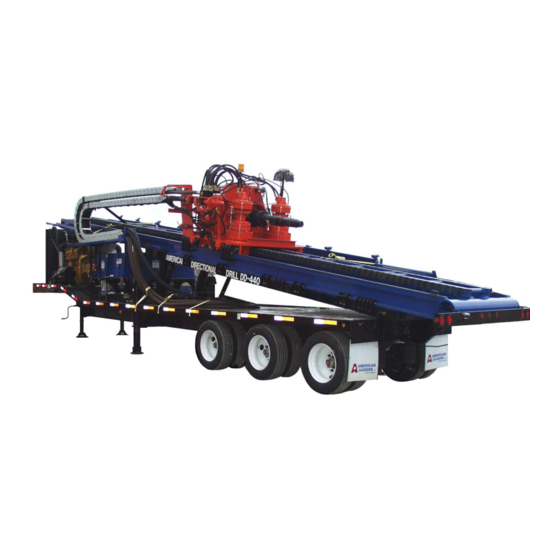
DD-440
Trailer Mounted Directional Drill
™
Operation & Safety
Instruction Manual
WARNING
Unsafe use of this equipment could result in serious injury or death. This manual contains
important instructions for the safe operation and recommended maintenance of your directional
drill. All who operate the directional drill must carefully read and understand this manual
before starting the machine. Keep this manual available both as a reminder for your experienced
operator and as a training aid for your new staff. Replacement manuals are available by
calling American Augers.
Advertisement
Table of Contents

Summary of Contents for American Augers DD-440
- Page 1 All who operate the directional drill must carefully read and understand this manual before starting the machine. Keep this manual available both as a reminder for your experienced operator and as a training aid for your new staff. Replacement manuals are available by calling American Augers.
- Page 2 We encourage you to call us for any and all of Innovative Leader in the Trenchless Industry. your drilling needs. Every effort has been made to cover adequately the operation of the DD-440™ Machine Serial Number ___________________ Engine Serial Number __________________...
-
Page 3: Table Of Contents
Table of Contents GENERAL INFORMATION ..............10 USE AND MAINTENANCE MANUAL ................. 10 1.1.1 DATA OF MANUAL ............................10 1.1.2 CONTENTS OF MANUAL ..........................10 1.1.3 WHO SHOULD USE THIS MANUAL ......................10 1.1.4 OWNERSHIP OF INFORMATION ......................... 10 MANUFACTURER IDENTIFICATION DATA ............... 10 MACHINE IDENTIFICATION DATA ................ - Page 4 2.2.12 DRILLER’S CONSOLE ........................... 21 PURPOSE OF THE MACHINE ..................21 STRUCTURE ........................21 TECHNICAL SPECIFICATIONS ................... 22 2.5.1 GENERAL FEATURES (DD-440) ........................22 2.5.2 DIESEL ENGINE ............................. 22 2.5.3 ELECTRIC SYSTEM ............................22 2.5.4 PERFORMANCE AS SUPPLIED ........................22 2.5.5...
- Page 5 FUNCTION OF THE MACHINE ................... 27 4.3.1 NORMAL OPERATION ..........................28 DANGEROUS ZONES—SAFE DISTANCES ..............28 QUALIFICATION OF THE OPERATOR ................ 29 POSITION OF THE OPERATOR ................... 29 CONTROLS AND INSTRUMENTS ................29 4.7.1 CONTROLS ..............................29 4.7.2 INSTRUMENTS AND CONTROLS (LIST) ..................... 30 4.7.3 ES!LOK®...
- Page 6 5.2.1 QUALIFICATION OF THE TECHNICIAN ..................... 49 5.2.2 FREQUENCY OF INSPECTIONS ........................49 SCHEDULED INSPECTION AND MAINTENANCE ........... 50 5.3.1 MAINTENANCE SCHEDULES OF DD-440 DIRECTIONAL DRILLS ............50 5.3.2 EMERGENCY STOP ............................51 5.3.3 GREASING ..............................51 5.3.4 ENGINE OIL ..............................51 5.3.5...
- Page 7 5.4.4 GAUGES AND INSTRUMENTS ........................54 5.4.5 BATTERIES ..............................54 OTHER INSPECTIONS AND MAINTENANCE (EVERY 250 HOURS) ...... 54 5.5.1 MOTOR MOUNTS AND RADIATORS ......................54 5.5.2 BREATHER PIPES ............................54 OTHER INSPECTION AND MAINTENANCE (EVERY 500 HOURS) ......54 5.6.1 ENGINE BELTS ...............................
- Page 8 Table of Figures Figure 1 Declaration of EC Conformity ..........................58 Figure 2 Limited Warranty Certification ........................... 59 Figure 3 Exit Pit Warning ..............................60 Figure 4 Pipe Wrench Warning ............................60 Figure 5 Electrical Hazard Warning ..........................61 Figure 6 Machine Labels ..............................62 Figure 7 Placement of Labels ............................
- Page 9 THIS PAGE LEFT BLANK INTENTIONALLY Page 9 Refer to the Safety Awareness Program in this manual before attempting to operate this machine...
-
Page 10: General Information
Section 2 Description 1.1.4 OWNERSHIP OF INFORMATION Section 3 Storage and Transport Section 4 Use American Augers, Inc. reserves all rights to the Section 5 Maintenance information in this manual. The manual cannot be Section 6 Diagnostic reproduced or photocopied in part or in whole... -
Page 11: Machine Identification Data
MACHINE IDENTIFICATION DATA current models of the DD-440 directional drill. Please call American Augers if you encounter Type: Directional Drill problems not addressed in this manual. Model: DD-440 Serial number: ..BE AWARE OF SAFETY INFORMATION. Year of manufacture: ... -
Page 12: Qualification Of Personnel
DD-440. These hazard alert signs insulating boots in case of striking a buried electric are placed on the machine to inform your cable. -
Page 13: Jobsite Safety
JOBSITE SAFETY • State the Personal Protective Equipment policy Horizontal Directional Drilling (HDD) safety • Every employee has the right and obliga- requires essentially the same philosophy as tion to refuse dangerous work construction. Safety must start at the management •... -
Page 14: Responsible Personnel
need to be addressed. Crews should be aware of • Vehicle operation specific safety and emergency procedures. • Mobile equipment operation • Noise 1.6.2 RESPONSIBLE PERSONNEL • Traffic control 1.6.2.1 COMPETENT PERSON • Verification of utilities • Security of jobsite and isolation of hazards The Competent Person is responsible for •... -
Page 15: Verify Utility Locates
1.6.3.2 SURFACE 1.6.3.3 OVERHEAD The job site surface should be thoroughly Overhead lines must be avoided. Overhead evaluated for indications of possible underground lines are of particular concern during mobilization/ hazards. demobilization, while handling drill pipe, or loading and unloading heavy equipment. If the voltage is •... -
Page 16: Traffic Control (Pedestrian And Vehicle)
concrete or other possible passive interference that • Any other safety equipment mandated by may hinder the operation, and discuss the identified other rules or required by the Owner or hazards. regulatory agency During the actual boring process, if abnormal •... -
Page 17: Response To Events
1.6.6.2 REAMING AND INSTALLATION immediately. The drill operator should shut down all PRECAUTIONS engines and under no circumstance should the operator attempt to reverse the bore to break The following precautions should be observed contact as further movement may cause a spark. during reaming and product installation: Emergency services and the gas utility company should be contacted immediately. -
Page 18: References
1.6.9 REFERENCES AMBIENT TEMPERATURES BETWEEN -40°C AND -15°C [-40°F AND +5°F]. For temperatures Directional Crossing Contractor’s Association not included in this range, contact American Augers. (DCCA), 2000. “Horizontal Drilling Safe Opera- Relative humidity allowed during work: 100% tions Guidelines.” Maximum altitude: 2000 m [6500 feet] above Equipment Manufacturers’... -
Page 19: Uses Not Allowed
4) Movement of the machine pulled or pushed whichever occurs first. Extensions can be granted by other machines. only by the President of American Augers and must 5) Use of the machine in explosive and/or be signed and enclosed with the certificate con- inflammable areas. -
Page 20: Request For Service Support
1.9.4 REQUEST FOR SERVICE SUPPORT NOTICE Notices, cautions, and warnings including For any request of service support in or out of important information are set apart from the the warranty period, contact your authorized dealer. text. Have available model number, serial number of the machine, and working hours indicated on the REFER TO: Section 1.5.1.1, SAFETY instrument located on both the main junction box... -
Page 21: Mud
(available separately). Operation of the mud pump forces a jet of drilling fluid out orifices in the The control console on the DD-440 is com- cutting head. At the same time, the pipe is advanced posed of a metal cabinet (See Figure 29). The by operation of the carriage. -
Page 22: Technical Specifications
Modify operational TECHNICAL SPECIFICATIONS procedure. 2.5.1 GENERAL FEATURES (DD-440) 2.5.1.1 WEIGHTS AND DIMENSIONS (IN 2.5.6 NOISE TRANSPORT POSITION) People working near and always inside the... -
Page 23: Storage Site Environment
3.1.2 STORAGE SITE ENVIRONMENT NOTICE Before putting the machine back in service, Temperature allowed: reconnect the es!lok® battery charger to either Between 0 and +50°C [32°F and 120°F]. a 12 v DC or 24 v DC supply and recharge the For temperatures between 0°... -
Page 24: Transportation
Tie the thrust subframe to the trailer with a chain in: Section 1, GENERAL INFORMATION and (Figure 45). Section 2.5.1, GENERAL FEATURES (DD-440). Unpin the locking bars from the anchor on the subframe and reconnect them to the carriage. Using 3.2.4 PREPARING THE MACHINE FOR... -
Page 25: Use
4.1.1.2 PROTECTION OF WIRES AND CABLES WORKING SITE PHYSICAL FEATURES Whether operating from the control console or 4.1.1 SITE PREPARATION from the driller’s cabin, the controls are connected to the drill by a series of hoses and cables. It is Maxi drills may be in place for much longer than important that these be protected from damage, and smaller, self-contained drills. -
Page 26: Lighting
tent soil, which cannot guarantee traction or support for support equipment. during work. REFER TO: Section 1.7, USES ALLOWED 4.2.1.1 TRANSPORT EQUIPMENT and Section 1.8, USES NOT ALLOWED. Make provisions to move the drill and 4.1.5 LIGHTING associated equipment subject to local highway laws. The drill requires the use of one truck tractor. -
Page 27: Increased Crew Size - Drill Side
General Labor loading on the mats. Excavator Operator The DD-440 should have support under the axles (tires), the landing gear, and the jacks midway 4.2.3 INCREASED CREW SIZE - EXIT SIDE down the trailer. -
Page 28: Normal Operation
fluid, also called mud), which is forced into the drill 4.4.1.2 CARRIAGE pipe by the mud pump. The mud circulates through the annulus of the bore and returns to the surface at Has movement forward and backward as well the entry point. as rotating parts, that present pinch points and a The actual bore dimension cannot be guaranteed danger of becoming entangled. -
Page 29: Qualification Of The Operator
Operation of the engines can be controlled on After delivery of the machine, a technician from the main junction box (Figure 14) or on the main the authorized dealer or from American Augers is control console (Figure 42). available for training one or more operators. After... -
Page 30: Instruments And Controls (List)
4.7.2 INSTRUMENTS AND CONTROLS Wrench Clamps Pressure, FIXED (LIST) Makeup Pressure 4.7.2.1 Figure 14 — Main Junction Box Rotary Pressure, MAKEUP Rotary Pressure, BREAKOUT Engine Management System (Engine A) Carriage Speed Select, LOW/HIGH Engine Management System (Engine B) Carriage, THRUST/PULLBACK Start (Engine A) Carriage Brake, FREE/LOCK Start (Engine B) -
Page 31: Es!Lok® Lockout System
4.7.3 ES!LOK® LOCKOUT SYSTEM CAUTION The exit side crew has to work in contact with Do not use starting fluid (ether). Immediate drill pipe and down hole tooling. Unexpected engine damage and personal injury may result. movement or rotation of the drill pipe or tooling can cause death or serious injury. -
Page 32: Operating With One Engine
4.9.3 POSITION THE DRILLER’S CONSOLE (Figure 42, Carriage, THRUST/PULLBACK) to slide the thrust frame to its drilling position. The control console on the DD-440 is com- posed of a metal cabinet (Figure 29). The console 4.9.10 FINISH SETUP may be used alongside the drill or installed in a driller’s cabin. -
Page 33: Anchor The Machine
4.9.11.2 OTHER METHODS OF ANCHORING THE DRILL Use the supplied hoses and cables to connect the drill console to the drill rig. Drillers using the DD-440 may choose to use additional methods of anchoring in addition to use 4.10 DRILLING PROCESS of the H-beam stakes. -
Page 34: Deep Crossings - The Setup
of guidance and locating the drill string head. Consult set to the required angle. This is from 10 to 18 the manufacturer of the locating system for exact degrees, depending on the characteristics of the operating instructions. crossing. The directional drill provides the means for The initial pipe section and cutting head are set rotating, advancing, and retracting the drill string. -
Page 35: Shallow Crossings - The Process
Directly behind the backreamer (away from the The DD-440 is not normally used in shallow drill pipe) a bearing swivel is installed. The bearing drilling (4.5 m [15 feet] or less). -
Page 36: Drilling Fluid - The Process
Simply mixing fluid in these quantities presents a 4.10.7 CALCULATION OF VOLUME OF challenge. A recycling system enables the driller to FLUID TO VOLUME OF SOIL reclaim most of the drilling fluid for re-use, and minimizes the amount of fresh water required for The three pieces of information needed to mixing. -
Page 37: Water Quality
ADDING AND REMOVING PIPE Support, RAISE/LOWER and Lower Pipe Support, RAISE/LOWER). Drill pipe sections used on the DD-440 are long, Following manufacturer’s instructions, resupply heavy objects. They must be handled carefully to the locating sonde with fresh batteries and calibrate prevent personal injury and to prevent damage to the locating receiver. -
Page 38: Adding Pipe (First Section With Wireline Location)
NOTICE Because Range 2 pipe sections can vary in 4.11.2 ADDING PIPE (FIRST SECTION WITH length, the wrenches on the DD-440 are WIRELINE LOCATION) adjustable to align the wrenches with the tool joints. Position the wrenches forward and... -
Page 39: The Rotary Brake
4.11.6.5 WIGGLE STEER™ Brake, FREE/LOCK down. To release the brake, lift Carriage Brake, FREE/LOCK. American Augers Wiggle Steer™ System is a means to rotate and thrust the drill pipe in a back 4.11.6 OTHER CONTROLS and forth motion to better open the bore path during 4.11.6.1 MUD SHUTOFF VALVES... -
Page 40: Installing A Wireline Guidance Instrument
(Figure 24) can keep the bore on line. again. Wireline guidance is a specialty that many drillers American Augers recommends the use of prefer to contract out. In that case, the subcontrac- AWG10 stranded copper wire, type MTW. The tor will specify the installation of the system and will... -
Page 41: Adding Pipe (Additional Sections)
Suitable splicing supplies and adhesive heat- console (Figure 42, Carriage, THRUST/PULL- shrink tubing are available from American Augers. BACK). Although cord grips are commercial items, they Cut the guidance wire at the box end of the first... -
Page 42: Setting Carriage Rotary Speed
Because Range 2 pipe sections can vary in the carriage spindle. length, the wrenches on the DD-440 are Use the carriage control on the main control adjustable to align the wrenches with the tool console (Figure 42, Carriage, THRUST/PULL- joints. -
Page 43: Calculating Rotary Torque Force
(Figure 34). Because there are two ranges, values are supplied by the pipe manufacturer. first determine the range selected. Example: In second gear, 2,550 psi indicated on the DD-440 4.11.11 CALCULATING ROTARY TORQUE gauge provides a torque of 44,170 pounds of force. -
Page 44: Start Of The Drilling Operation
DD-440. It is normal for drilling fluid to DANGER escape from the cutting head even if the mud pump is not operating. -
Page 45: End Of Pullback Operations
operator must decide whether to enlarge the bore by swivel. A suitable pulling eye is connected both to reaming. Factors include the soil conditions, length the swivel and to the pipe or cable to be installed. of the bore, and the flexibility of the pipe or cable being installed. -
Page 46: Emergency Stop
engine to cool. Switch off the engine by pushing the 4.19 CHECKS DURING OPERATION Emergency Stop button on the main junction box (Figure 14, Engine A and Engine B, STOP) or on During drilling, it is absolutely necessary to the main control console (Figure 42, Engine A and monitor instruments and functions regularly. -
Page 47: Start After Use Of Es!Lok
to the right of the control console (Figure 29). The 4.23 OPERATION UNDER AMBIENT Competent Person enables operation by pressing TEMPERATURES BETWEEN -40°C & -15°C the start button on the es!lok® unit worn on the belt. [-40°F TO +5°F] The normal indication is a green light on the receiver box and a flashing green light on the unit worn on the Only the machines especially arranged at the belt. -
Page 48: Starting The Engine (With The Machine Kept Warm Through Pre-Heaters)
4.23.4.1 DRAIN THE FLUID COURSE The fluid course on the DD-440 can be drained WARNING by breaking the pipe tool joint nearest the wrenches and by opening the small valve behind the hammer Pre-heating device operates on high voltage union where the mud supply hose is connected. -
Page 49: Maintenance
DISTANCES For any operation which is not described in this manual or for extra information, please contact WARNING AMERICAN AUGERS or the nearest dealer directly. Carry out maintenance when the machine is off. Before operating, clean the machine and lock 5.2.2 FREQUENCY OF INSPECTIONS... -
Page 50: Scheduled Inspection And Maintenance
inspections must be carried out. For example, at Fill to lower edge of opening. 250 working hours, also perform the items listed in Pump drive gearbox; daily and weekly schedules. See Figure 36. Remove dipstick. Add oil to mark shown on dipstick. SCHEDULED INSPECTION AND MAINTENANCE 5.3.1.3 Monthly (or 250 hours) -
Page 51: Emergency Stop
NOTICE 5.3.6 AIR FILTERS At every inspection all the inspections with previous schedules must be carried out. Do not clean the air cleaner unless the instrument (Figure 43) shows a need for service. At each 5.3.2 EMERGENCY STOP inspection of the air cleaner, also inspect the rubber evacuator valve. -
Page 52: Gearboxes And Pump Drive
Check the level in the tank using the transparent tank. Clean suction filter, breather pipe, and mag- gauge mounted on it. If the level is too low, add oil netic cap with a lint free cloth and clean oil. as far as the mark indicates the level. The level must be checked when the oil is cold, with all cylinders WARNING retracted. -
Page 53: Welding
suitable oil until it comes out the level hole. For 5.3.11 RADIATOR draining the oil, remove the plug in the bottom of the gearbox. Catch the oil in a suitable container. This category includes the engine radiator and Dispose of used oil in a lawful manner. hydraulic oil radiator. -
Page 54: Leaks
5.4.3 LEAKS is normally enough to clean terminals and battery box. After cleaning, rinse thoroughly with clean Inspect the machine for leaks of gear oil, hy- water. Coat the terminals with grease in order to draulic oil, engine coolant, and fuel. Big leaks should prevent future corrosion. -
Page 55: Cooling System
In case of low engine oil pressure, an automatic OTHER CHECKS (EVERY 1000 HOURS device stops the engine. Check for low oil level or OR EVERY YEAR) other fault. If necessary, contact American Augers 5.7.1 ENGINE FUEL FILTERS technical assistance service. REFER TO Attachment 1, Caterpillar C-11 Tier 6.1.3 ENGINE COOLANT TEMPERATURE... -
Page 56: Clogged Oil Filter
Competent Person or loss of signal will lock out the NOTICE rotary and carriage function. American Augers declines any responsibility REFER TO: Attachment 2, ES!LOK® Opera- in case of recycling or reusing of parts of the tion and Maintenance Instruction Manual. - Page 57 THIS PAGE LEFT BLANK INTENTIONALLY Page 57 Refer to the Safety Awareness Program in this manual before attempting to operate this machine...
-
Page 58: Figure 1 Declaration Of Ec Conformity
Figure 1 Declaration of EC Conformity Not required in North America Page 58 Refer to the Safety Awareness Program in this manual before attempting to operate this machine. -
Page 59: Figure 2 Limited Warranty Certification
Figure 2 Limited Warranty Certification Page 59 Refer to the Safety Awareness Program in this manual before attempting to operate this machine... -
Page 60: Figure 3 Exit Pit Warning
Drilling operations may require contraction of a pit to receive the cutter or mud motor on the exit side of of ladders used in the pit and personal safety equipment. American Augers recommends that the owner become the crossing. familiar with the requirements of 29CFR1910. Information... -
Page 61: Figure 5 Electrical Hazard Warning
Figure 5 Electrical Hazard Warning WARNING Electrical Hazard Erect safety barrier 8m (25 ft) beyond machine. Make sure grounding stake is properly installed. Keep spectators away. Electrical Bonding Cable (not supplied) electronically bonds mud mixer/cleaner to drill (to maintain equal electrical potential in event of an electric strike.) Page 61 Refer to the Safety Awareness Program in this manual before attempting to operate this machine... -
Page 62: Figure 6 Machine Labels
Figure 6 Machine Labels 15GB7155 8NP41101 8NP41102 8NP41107 15GB7116 8NP41108 15GB7118 8NP41209 15GB7119 15GB7113 Page 62 Refer to the Safety Awareness Program in this manual before attempting to operate this machine. - Page 63 Figure 6 Machine Labels, continued 8ED02120 8NP41161 8ED02240 8NP41389 8NP41205 8NP41391 8NP41206 8NP41404 8NP41103 8NP41483 8NP41117 Page 63 Refer to the Safety Awareness Program in this manual before attempting to operate this machine...
-
Page 64: Figure 7 Placement Of Labels
Figure 7 Placement of Labels 8NP41389 15GB7118 15GB7155 Page 64 Refer to the Safety Awareness Program in this manual before attempting to operate this machine. - Page 65 Figure 7 Placement of Labels, continued 8NP41107 8NP41108 15GB7119 15GB7113 8NP41101 8NP41161 8NP41404 Page 65 Refer to the Safety Awareness Program in this manual before attempting to operate this machine...
-
Page 66: Figure 8 Placement Of Labels
Figure 8 Placement of Labels 15GB7113 15GB7119 8NP41101 Page 66 Refer to the Safety Awareness Program in this manual before attempting to operate this machine. - Page 67 Figure 8 Placement of Labels, continued 8NP41483 Page 67 Refer to the Safety Awareness Program in this manual before attempting to operate this machine...
-
Page 68: Figure 9 Placement Of Labels
Figure 9 Placement of Labels 8NP41102 Page 68 Refer to the Safety Awareness Program in this manual before attempting to operate this machine. - Page 69 Figure 9 Placement of Labels, continued 15GB7119 8NP41102 Page 69 Refer to the Safety Awareness Program in this manual before attempting to operate this machine...
- Page 70 Figure 9 Placement of Labels, continued 8NP41391 Page 70 Refer to the Safety Awareness Program in this manual before attempting to operate this machine.
- Page 71 Figure 9 Placement of Labels, continued 8NP41117 8NP41103 15GB7116 15GB7119 8NP41101 8NP41102 Page 71 Refer to the Safety Awareness Program in this manual before attempting to operate this machine...
-
Page 72: Figure 10 Lifting The Drill
Figure 10 Lifting the Drill Figure 11 Drill Unit Dimensions Page 72 Refer to the Safety Awareness Program in this manual before attempting to operate this machine. -
Page 73: Figure 12 Site Layout
Figure 12 Site Layout Figure 13 Entry Pit Page 73 Refer to the Safety Awareness Program in this manual before attempting to operate this machine... -
Page 74: Figure 14 Main Junction Box
Figure 14 Main Junction Box Page 74 Refer to the Safety Awareness Program in this manual before attempting to operate this machine. -
Page 75: Figure 15 Hose Caps
Figure 15 Hose Caps Figure 16 Setup Valves Page 75 Refer to the Safety Awareness Program in this manual before attempting to operate this machine... -
Page 76: Figure 17 Installing The Wrench
Figure 17 Installing the Wrench Figure 18 Handrails Page 76 Refer to the Safety Awareness Program in this manual before attempting to operate this machine. -
Page 77: Figure 19 Wireline Conductor
Figure 19 Wireline Conductor Figure 20 Cord Grip and Side Entry Sub Page 77 Refer to the Safety Awareness Program in this manual before attempting to operate this machine... -
Page 78: Figure 21 Wireline Conductor Splice
Figure 21 Wireline Conductor Splice Figure 22 Crimping Tool Page 78 Refer to the Safety Awareness Program in this manual before attempting to operate this machine. -
Page 79: Figure 23 Electric Heat Gun
Figure 23 Electric Heat Gun Figure 24 Wireline Guidance System Page 79 Refer to the Safety Awareness Program in this manual before attempting to operate this machine... -
Page 80: Figure 25 Wireline System Layout
Figure 25 Wireline System Layout Figure 26 Tooling Page 80 Refer to the Safety Awareness Program in this manual before attempting to operate this machine. -
Page 81: Figure 27 Down Hole (Mud) Motor
Figure 27 Down Hole (Mud) Motor Figure 28 Steering With cutter head positioned as shown, and thrust without rotation, bore moves in direction of arrow. Clock face will be represented on locating receiver. Page 81 Refer to the Safety Awareness Program in this manual before attempting to operate this machine... -
Page 82: Figure 29 Control Console General Arrangement (Inside Optional Cabin)
Figure 29 Control Console General Arrangement (Inside Optional Cabin) Control Console Es!lok® Receiver Driller’s Chair Figure 30 Ends of Control Console Wireline Signal (+) Wireline Signal (-) Es!lok® System Connection Auxiliary 12 Volt D.C. Page 82 Refer to the Safety Awareness Program in this manual before attempting to operate this machine. -
Page 83: Figure 31 Rotary Carriage Disable
Figure 31 Rotary Carriage Disable Figure 32 Battery Box Page 83 Refer to the Safety Awareness Program in this manual before attempting to operate this machine... -
Page 84: Figure 33 Table To Convert Psi Reading To Rotary Torque
Figure 33 Table to Convert PSI Reading to Rotary Torque Page 84 Refer to the Safety Awareness Program in this manual before attempting to operate this machine. -
Page 85: Figure 34 Table To Convert Psi Reading To Thrust/Pullback Force
Figure 34 Table to Convert PSI Reading to Thrust/Pullback Force Page 85 Refer to the Safety Awareness Program in this manual before attempting to operate this machine... -
Page 86: Figure 35 Table To Convert Psi Reading To Wrench Force
Figure 35 Table to Convert PSI Reading to Wrench Force Page 86 Refer to the Safety Awareness Program in this manual before attempting to operate this machine. -
Page 87: Figure 36 Maintenance Schedule
Figure 36 Maintenance Schedule Figure 37 Approved Replacement Fluids Page 87 Refer to the Safety Awareness Program in this manual before attempting to operate this machine... -
Page 88: Figure 38 Volume Of Soil Formula
Figure 38 Volume of Soil Formula Figure 39 Steering Radius Page 88 Refer to the Safety Awareness Program in this manual before attempting to operate this machine. -
Page 89: Figure 40 Wigglesteer™ Codes
Figure 40 WiggleSteer™ Codes Page 89 Refer to the Safety Awareness Program in this manual before attempting to operate this machine... -
Page 90: Figure 41 Drill Rig Nomenclature
Figure 41 Drill Rig Nomenclature Page 90 Refer to the Safety Awareness Program in this manual before attempting to operate this machine. -
Page 91: Figure 42 Upper And Main Control Console
Figure 42 Upper and Main Control Console Page 91 Refer to the Safety Awareness Program in this manual before attempting to operate this machine... -
Page 92: Figure 43 Air Cleaner
Figure 43 Air Cleaner Figure 44 Manual Crank Page 92 Refer to the Safety Awareness Program in this manual before attempting to operate this machine. -
Page 93: Figure 45 Tie Down Chain
Figure 45 Tie Down Chain Page 93 Refer to the Safety Awareness Program in this manual before attempting to operate this machine... - Page 94 American Augers, Inc. 135 US Route 42 P.O. Box 814 West Salem, Ohio 44287 www.americanaugers.com Always include machine serial number when ordering parts. Due to our continuing product improvement, machine specifications are subject to change without notice. Part Number: 44DD10000TR...
Need help?
Do you have a question about the DD-440 and is the answer not in the manual?
Questions and answers