Sign In
Upload
Manuals
Brands
Amazone Manuals
Farm Equipment
BBG UX 5200
Amazone BBG UX 5200 Manuals
Manuals and User Guides for Amazone BBG UX 5200. We have
1
Amazone BBG UX 5200 manual available for free PDF download: Operator's Manual
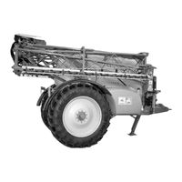
Amazone BBG UX 5200 Operator's Manual (168 pages)
Trailed Field Sprayer
Brand:
Amazone
| Category:
Farm Equipment
| Size: 11 MB
Table of Contents
Table of Contents
5
1 User Advice
9
Purpose of the Document
9
Information about Directions in this Instruction Manual
9
Illustrations Used
9
2 General Safety Advice
10
Obligations and Liability
10
Illustration of Safety Advice
11
Designed Use of the Machine
12
Designed Equipment of the Field Sprayer
12
Attention When Using Specific Crop Protection Agents
13
Organising Measures
13
Safety Devices and Guards
14
Informal Safety Measures
14
Training of the Staff
14
Safety Measures and Normal Operation
15
Danger from Residual Power
15
Danger Points in Particular
15
Maintenance and Repair, Remedy of Faults
15
Constructional Changes
15
Alterations or Changes
16
Spare Parts and Wearing Parts and Auxiliary Parts
16
Cleaning and Disposal
16
Workplace of the Operator
16
Safety Symbols and Other Identifications on the Machine
17
Danger When Not Adhering to the Safety Advice
21
Safety Conscious Operation
21
Safety Advice for the Operator
21
General Safety and Accident Prevention Advice
21
Operating Devices
22
Mounted Implements/Trailed Implements
23
Operation with PTO Shafts
24
Hydraulic System
25
Electric Outfit
25
Brake System
26
Bolted Joints, Tyres
26
Maintenance-, Repair- and Care
26
2.19.10 Plant Protection Implements for Surface Cropping
27
3 Description of Product
28
Function
33
Explanation for the Valve Chest Actuation
34
Danger Zones
37
Positioning of Safety Symbols and Other Identifications
37
Conformity Declaration
40
Technical Data
41
Overall Dimensions UX with Super-S Sprayer Boom
41
Overall Dimensions UX with L Sprayer Boom
41
Data Sheet
42
Weights Basic Implement, Axles and Tyres
43
Weights Sprayer Booms
43
Details about Noise Level
43
Liquid Circuit
44
4 Assembly and Function
45
Hydraulic System
45
Setting the System Setting Screw on the Hydraulic Block
46
Oil Filter
47
Hydraulic Pump Drive
47
Running Gear and Tyres
47
Running Gear with Unbraked Axle
47
Running Gear with Braked Track Following Steering Axle
48
Track Following Steering Axle
48
Dual Circuit Air Brake System
49
Parking Brake
52
Hydraulic Brake System
54
Tyres
55
Draw Bars
56
Straight Draw Bar and Hitch Draw Bar
56
Hydraulic Jack
56
Mechanic Jack
57
Working Platform
57
Agitators
58
Pump Equipment
59
Filter Equipment
60
Filling Sieve
60
Suction Filter
60
Self Cleaning Pressure Filter
61
Nozzle Filters
62
Bottom Sieve in the Induction Bowl
62
Fresh Water Rinse Tank
63
Induction Bowl with Filling Port ECOFILL and Canister Flushing
64
Hand Wash Tank
65
Sprayer Boom
66
Sprayer Boom with Profi Folding (I, II and III)
67
Super-S-Boom
67
L-Boom
69
4.13.3.1 Setting the Hydraulic Throttle Valves
70
Hydraulic Joints - Tilt Adjustment
71
Fig. 65
72
Throttle Valve - Locking Swing Compensa- 11 9 6 4
72
Valves Are Located on the Hydraulic Ram of
72
Throttle Valve - Angling down Left Hand 10 8 5 3
72
Spray Lines
73
Technical Data
73
Fig. 66
73
Single Nozzles
76
Multiple Nozzles
76
5 Special Optional Equipment
78
Special Options for Liquid Fertilising
78
3-Ray Nozzles
78
5- and 8-Hole Nozzles
79
Drag Hose Equipment for Super-S-Boom
80
Spray Pistol, with 0.9 M Long Spray Tube, Without Pressure Hose
81
Pressure Hose up to 10 Bar, E.g. for Spray Pistol
81
Traffic Lights
81
Foam Marker
82
Permanent Working Width Reduction on the Super S Boom
83
Pressure Circulation System (DUS)
84
Hose Filters for Spray Lines
86
Urea Filter
86
6 Operator Terminal
87
7 Overview Valve Chest Operation
88
Spraying Operation
88
Sucking off Induction Bowl
89
Diluting Urea in the Induction Bowl and Sucking off
90
Pre-Cleaning the Canister Using the Spray Mixture
91
Diluting the Residual Amount in the Spray Mixture Tank
92
Cleaning the Field Sprayer with a Filled Spray Mixture Tank
93
Filling Via Suction Hose on the Filling Port
95
Tank Interior Cleaning
96
Exterior Cleaning
97
8 Putting into Operation
98
Initial Operation
99
Calculation of the Payload
99
PTO Shaft
100
First Fitting and Matching the PTO Shaft
101
Hitching up
103
Unhitching
105
Manoeuvring with the Unhitched Trailed Sprayer
106
Initial Operation with the Service Brake System
107
Checks Prior to any Travelling
107
Checks after any Travel
107
Preparing Spraying Operation
108
Preparing the Spray Mixture
109
Calculating the Filling or Refilling Quantities
110
Filling Table for Finishing off Remaining Field Areas
111
Filling with Water
112
Inducting Spray Agents
113
Inducting Liquid Agents
114
Inducting Powdered Agents and Urea
115
Inducting with ECOFILL
116
Pre-Cleaning the Canister with the Spray Mixture
117
Clean Canister with Rinse Water
118
Spraying Operation
119
Inputting Job Related Data into the
121
Spraying Crop Protection Liquid
121
Spraying Operation
123
8.10.3.1 Fault Messages and Audible Alarm Signals
124
Measures for Drift Reduction
124
Residual Amounts
125
Removal of Residual Amounts
125
Cleaning
128
Cleaning the Sprayer with a Filled Tank
129
Storing over Winter or Prolonged Standstill
130
Cleaning the Suction Filter
131
9 Maintenance, Repair and Care Work
132
Cleaning
133
Lubricants
134
Overview - Greasing Points
134
Draw Bars
135
Axle and Brake System
136
Lubrication
137
Maintenance Work
139
Parking Brake
143
Tyres / Wheels
144
Tyre Air Pressure
144
Fitting Wheels
144
Hydraulic System
145
Electric Traffic Lights
146
Pump - Maintenance and Remedy in Case of Malfunction
147
Checking the Oil Level
147
Oil Change
147
Pump Drive
147
Checking the Belt Tensioning / Adjustment
147
Exchanging Drive Belts
148
Cleaning
148
Remedy in Case of Malfunction
148
Check and Exchange Suction- and Pressure-Side Valves
149
Checking and Exchanging the Piston Diaphragms
150
Calibrating the Flow Meter
152
Nozzles
152
Fitting the Nozzles
153
Dismantling the Diaphragm Valve in Case of Dripping Nozzles
153
Hose Filters
153
Hints for Checking the Field Sprayer
154
Check List for Maintenance Work
155
Daily
155
Bolt Torques
156
10 Spray Rate Chart
157
Spray Rate Chart for Flat Fan-, Anti Drift-, Injector- and Airmix Nozzles, Spraying Height 50 CM
157
Spray Rate Table for 3-Ray Nozzles, Spraying Height 120 CM
161
Spray Rate Table for 5- and 8-Hole Nozzles (Permissible Pressure Range 1-2 Bar)
162
Spray Rate Table for Drag Hose Equipment (Permissible Pressure Range 1-4 Bar)
164
Conversion Table for Spraying Liquid Fertiliser Ammonium Nitrate - Urea Suspension (AUS)
166
Advertisement
Advertisement
Related Products
Amazone BBG UX 4200
Amazone BBG Taurus 3000
Amazone 00 1420 502 0
Amazone 102877
Amazone AD - 253 Special
Amazone AD - 303 Special
Amazone AD - 303 Super
Amazone AD - 353 Super
Amazone AD - 403 Super
Amazone AD 2500 Special
Amazone Categories
Farm Equipment
Tiller
Spreader
Desktop
Paint Sprayer
More Amazone Manuals
Login
Sign In
OR
Sign in with Facebook
Sign in with Google
Upload manual
Upload from disk
Upload from URL