Sign In
Upload
Manuals
Brands
Alstom Manuals
Voice Recorder
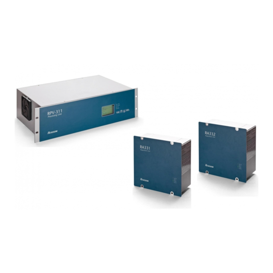
Reason RPV311
Alstom Reason RPV311 Manuals
Manuals and User Guides for Alstom Reason RPV311. We have
1
Alstom Reason RPV311 manual available for free PDF download: Technical Manual
Alstom Reason RPV311 Technical Manual (350 pages)
Distributed Multifunction Fault Recorder
Brand:
Alstom
| Category:
Voice Recorder
| Size: 8 MB
Table of Contents
Table of Contents
3
Chapter 1 Introduction
15
Chapter Overview
16
Foreword
17
Target Audience
17
Nomenclature
17
Acronyms and Abbreviations
17
Product Scope
20
Unpacking
21
External Indication
22
RPV311 Nameplate
22
RA331, RA332, and RA333 Nameplate
22
Key Features
24
Features and Functions
24
Compliance
26
Functional Overview
27
Figure 1: Functional Design Overview
27
Programs under the GPL 2 License
28
Ordering Options
29
Rpv311
29
Ra331
30
Ra332
31
Ra333
33
Chapter 2 Safety Information
34
Chapter Overview
35
Health and Safety
36
Symbols
37
Installation, Commissioning and Servicing
38
Lifting Hazards
38
Electrical Hazards
38
Fusing Requirements
39
Equipment Connections
40
Pre-Energisation Checklist
41
Peripheral Circuitry
41
Upgrading/Servicing
42
Decommissioning and Disposal
43
Standards Compliance
44
EMC Compliance
44
Product Safety: 2006/95/EC
44
R&TTE Compliance
44
Chapter 3 Hardware Design
45
Chapter Overview
46
Hardware Architecture
47
Processing Capability
47
Figure 2: RA333, RA332, RA333 and RPV311
47
Mechanical Implementation
49
Rpv311
49
Figure 3: Front View of the RPV311
50
Figure 4: Back View of the RPV311
50
Ra331
51
Ra332
52
Figure 5: Front and Back Views of the RA331
52
Figure 6: Front and Back Views of the RA332
53
Ra333
54
Figure 7: Front and Back Views of the RA333
54
Chapter 4 Configuration
57
Chapter Overview
58
Accessing the Equipment Configuration
59
Figure 8: Initial Configuration Screen
59
Configuration History
60
Equipment
61
Identification
61
Figure 9: Equipment Identification Configuration Section
61
Synchronization
62
Communications
63
Figure 10: Equipment Ethernet Configuration Section
63
Figure 11: Equipment Serial Port Configuration Section
64
Acquisition with Remote Acquisition Modules
65
Figure 12: Links between RPV and Acquisition Modules Configuration Section
66
Acquisition with Sampled Values
67
Figure 13: Analog Inputs Configuration Section
67
Figure 14: Sampled Values Subscriptions Links Configuration Section
68
Access Control
69
Figure 15: Analog Inputs Configuration Section for Sampled Values Channels
69
User
70
Figure 16: Equipment Access Control Configuration Section
70
Figure 17: Adding New User Section
71
Record Management
72
Figure 18: Changing the Administrator Password Section: Changing the Administrator Password Section
72
Auto Upload
73
Figure 19: Record Management Configuration Section
73
Figure 20: Auto Upload Configuration Section
74
Figure 21: Email/Fax Configuration
75
Voltage Circuit
76
Figure 22: Adding and Editing Voltage Circuits
77
Current Circuits
78
Figure 23: Adding and Editing Current Circuits
79
Power Circuit
80
Figure 24: Adding and Editing Power Circuits
80
Digital Channels
81
Figure 25: Adding and Editing Digital Channels
82
DC Channels
83
Figure 26: Adding and Editing DC Channels
84
Thresholds
85
Threshold
85
Adding New Voltage Thresholds
86
Adding New Current Thresholds
87
Figure 27: Adding and Editing a Voltage Threshold
87
Adding New Power Thresholds
89
Figure 28: Adding and Editing a Current Threshold
89
Figure 29: Adding and Editing a Power Threshold
90
Adding New Digital Thresholds
92
Adding New DC Thresholds
92
Figure 30: Adding and Editing a DC Threshold
93
Fault Recorder
94
Trigger'D Recording
94
Figure 31: Fault Recorder - Triggered Recording Configuration Section
94
Fault Records
94
Continuous Recording
95
Figure 32: Fault Recorder - Continuous Recording Configuration Section
95
Disturbance Recorder
97
Trigger'D Recording
97
Figure 33: Disturbance Recorder - Trigger'D Recording Configuration
97
Continuous Recording
98
Figure 34: Disturbance Recorder - Continuous Recording Configuration Section
98
Traveling Waves Recorder
100
Figure 35: Traveling Waves Recorder - Trigger'D Recording Configuration Section
100
Recommended Sources of Trigger
101
Steady-State
102
Average Series
102
Harmonics
102
Figure 36: Steady-State Recorder - Average Series Configuration Section
102
Flicker
103
Figure 37: Steady-State Recorder - Harmonics Configuration Section
103
Figure 38: Steady-State Recorder - Flicker Configuration Section
104
Groups
105
Figure 39: Adding and Editing a Group
105
Relays
106
On Time
106
Relays 2, 3, and
106
Figure 40: Relays on Time Configuration Section
106
Figure 41: Relay Signaling Events Configuration Section
107
Pmu
108
Data
108
Communication
108
Modbus
110
Figure 42: MODBUS Configuration Section
110
Dnp3
112
Configuring the DNP3 Function
112
DNP3 Configuration Example
112
Figure 43: Digital Channels Configured
112
Figure 44: Analog Channels Selected
114
Chapter 5 Operation
117
Chapter Overview
118
Local Interface
119
Status Indicators
119
Menu Navigation
119
Local Interface Menus
119
Figure 45: Local Interface of the RPV311
119
Figure 46: Status Monitoring Sequence
121
Figure 47: Monitoring Sequence
123
Figure 48: Records Monitoring Sequence: Fault Disturbance, TW and Average Series
125
Figure 49: Records Monitoring Sequence: Harmonics, Flicker and SOE
126
Figure 50: Equipment Settings Monitoring Sequence
128
Figure 51: Circuit and Channel Settings Monitoring Sequence
129
Figure 52: Relays, PMU and MODBUS Settings Monitoring Sequence
130
Figure 53: General Information Monitoring Sequence
132
Monitoring Web Interface
133
Accessing the Monitoring Web Interface
133
Navigating
135
Figure 54: Default Screen for Browsing on the Web Interface
135
Status
136
Figure 55: Equipment Status Screen
136
Figure 56: Link Status Screen
137
Log
138
Manual Trigger
138
Figure 57: Log Screen
138
Records
139
Figure 58: Manual Trigger Screen
139
Figure 59: Fault Recorder Screen
140
Figure 60: Fault Recorder Screen
141
Figure 61: Traveling Wave Recorder Screen
142
Figure 62: Steady-State Recorder Screen
143
Figure 63: SOE Recorder Screen
144
Monitoring
145
Figure 64: Monitoring with Plots
147
Figure 65: Monitoring Circuit Quantities Via Web Interface
148
Figure 66: Monitoring the Status of Digital Channels
149
Configuration History
150
General Information
150
Figure 67: Configuration History Screen
150
Figure 68: General Information Screen
151
Figure 69: Setup Screen
152
COMTRADE Files Download
154
Chapter 6 Records
155
Chapter Overview
156
Continuous and Triggered Fault Records
157
Recorded Values
157
Recording Times by Trigger
158
Sampling Rate
158
Re-Trigger and Record Concatenation
158
Trigger Burst Limiter
159
Figure 70: Concatenation Event Example
159
Figure 71: Example of an Event Without Concatenation
159
Continuous and Trigger'D Disturbance Records
161
Recorded Values
161
Recording Times by Trigger
161
Sampling Rate
162
Re-Trigger and Record Concatenation
162
Trigger Burst Limiter
162
Traveling Wave Fault Records
163
Pre-Conditions
163
Sampling Rate and Acquisition
163
Recording Times
163
Steady-State Records
165
Average Series Harmonics Flicker
165
SOE - Sequence of Events Records
167
Record Format and Naming, and Mass Storage Capacity
168
Record Format
168
Record Naming
168
Mass Storage Capacity
169
Record Management and Access
171
Chapter 7 TW Fault Locator
173
Chapter Overview
174
TWFL Overview
175
Figure 72 - TW Fault Locator Architecture Overview
175
TW Fault Location Information
177
Maximum Number of Lines Monitored by the TW Fault Locator
177
Accuracy and TWFL with Cvts
177
Underground and Overhead Cables
177
Automatic Fault Location
178
How to Test the TW Fault Location in Lab
179
Three Terminal Line Application
180
Figure 73 - Typical Circuit Three-Terminal Application
180
Examples
181
Figure 74 - Three Terminal Line Application
181
Figure 75 - TW Fault Location Example 1
182
Figure 76 - TW Fault Location Example 2
182
Chapter 8 PMU
183
Chapter Overview
184
Synchrophasor Measurement and Broadcast
185
Reported Values
185
Accuracy Limits
186
Communication Ports, Transmission Rates
186
Timestamp
187
Configuration
187
Standards Compliance
187
WMU - Waveform Measurement Unit
188
Chapter 9 MODBUS
189
Chapter Overview
190
Description
191
Register Types
191
Status
191
Analog Data
192
Digital Channels
192
Configuration
192
Chapter 10 DNP3
193
Chapter Overview
194
Description
195
Chapter 11 GOOSE Message Detection
197
Chapter Overview
198
Description
199
Chapter 12 Software - RPV Tools
201
Chapter Overview
202
RPV Tools Description
203
RPV Tools Installation
203
Scanner
204
Figure 77: Directory of the Records Received of the Equipment
209
Configuration Tool
210
Figure 78: Configuration Tool Main Screen
210
TW Fault Locator
214
Figure 79: Fault Locator Interface
218
Figure 80: Graphical Tool of Fault Locator Interface
220
GOOSE Configurator
221
Figure 81: Initial Screen of the GOOSE Configurator
222
Figure 82: Screen to Configuration on the SCL File
224
Figure 83: Association of a GOOSE Control Block with a Digital Input
225
Figure 84: Filter Parameters
226
Chapter 13 Software - RPV Manager
229
Chapter Overview
230
Requirements
231
Software Description
232
RPV Manager Main Window
232
Figure 85 - RPV Manager Main Window
232
Figure 86: Records Download
232
Figure 87: Alarms Tab
233
Figure 88: Configuration Tab
234
RPV Manager Settings
235
Figure 89: Device Window
237
Figure 90: Current Circuit Name
238
Figure 91: Terminal Name Configuration
239
Figure 92: Percentage of Records Chart
242
Figure 93: Polling Configuration
243
Automatic TW Faul Location
244
Figure 94: about Window
244
Polling and Refresh
246
Figure 95: RPV Manager TWFL Methods
246
Chapter 14 Communications
249
Chapter Overview
250
Communication Interfaces
251
Electrical and Optical Ethernet
251
Figure 96: Electrical and Optical Ethernet Inputs
251
Serial Port
252
Figure 97: Serial Communication Port
252
Communication Ports and Protocols
254
Direct Communication Using the Electrical Ethernet Port
255
Figure 98: Local Communication with Equipment Using the Electrical Ethernet Port Architecture
255
Checking the Connection
256
Communication through Network Using the Electrical Ethernet Port
257
Figure 99: Communication through Network Using the Electrical Ethernet Port Architecture
257
Communication through Network Using the Serial Port
258
Accessing the Equipment
259
Computer Support Applications
259
Minimum Computer Requirements
259
Communication Configuration
260
Auto Upload
260
Chapter 15 Installation
261
Chapter Overview
262
Handling the Goods
263
Receipt of the Goods
263
Unpacking the Goods
263
Storing the Goods
263
Dismantling the Goods
263
Normal Use of the Equipment
264
Mounting the Device
265
RPV311 Mechanical Installation
265
RA331, RA332 and RA333 Mechanical Installation
265
Figure 100: Minimum Distances for the Equipment Mounting
265
Figure 101: Single Mounting Panel to Install One Remote Acquisition Module (RA331/332) in a 19-Inch Rack
266
Figure 102: Mounting Panel to Install Two Remote Acquisition Modules (RA331/332) in a 19-Inch Rack
267
Cables and Connectors
268
Power Supply Connections
268
Figure 103: Pre-Insulated Tubular Pin Terminals
268
Figure 104: Header Connector Assembly
268
RPV311 AC and DC Power Connection
269
RA331, RA332 and RA333 AC and DC Power Connection
269
Figure 105: AC/DC Power Connection
269
Figure 106: AC/DC Power Connection
269
Powering up
270
Earth Connnection
270
Connection between RPV311 and RA331, RA332 or RA333
271
Figure 107: RPV311 Grounding
271
Figure 108: RA33X Grounding
271
Figure 109: RPV311 Fiber Optic Connectors
272
Figure 110: RA331, RA332 and RA333 Fiber Optic Connectors
272
Figure 111: Connection between RPV311 and the RA331, RA332 or RA333
273
Analog Voltage Inputs (50/60 Hz)
274
Figure 112: Screws of the Back Panel
274
Figure 113: Analog Input Terminals
275
Figure 114: Screws of the Back Panel
275
Figure 115: Internal Jumper
276
High-Speed Analog Voltage Inputs (TW)
279
Figure 116: Analog Input Terminals to TW Measurement
279
Analog Current Inputs
280
Figure 117: Analog Input Terminals
280
Figure 118: Screws of the Back Panel
281
Figure 119: Internal Jumper
281
Analog DC Transducer Inputs ± 10 V
284
Figure 120: Analog Input Terminals
284
Figure 121: Screws of the Back Panel
285
Figure 122: Internal Jumper
285
Analog DC Transducer Inputs ± 20 Ma
286
Figure 123: Connection Diagram of DC Transducer Inputs ± 10 V
286
Figure 124: Analog Input Terminals
286
Figure 125: Screws of the Back Panel
287
Figure 126: Internal Jumper
287
Current Clamps
288
Figure 127: Connection Diagram of DC Transducer Inputs ± 20 Ma
288
Figure 128: Polarity of the Current Clamp Connection
288
Digital Inputs
289
Time Synchronization Inputs
289
Figure 129: Digital Input Terminals
289
Figure 130: Connection Diagram of Digital Inputs
289
Figure 131: Electrical and Optical Inputs for Sync Using IRIG-B
290
Figure 132: Connection Diagram of Electrical Synchronism Inputs
290
Dry Contact Relays
291
Figure 133: Connections Diagram of Optical Synchronism Inputs
291
Figure 134: Dry Contact Relays of the RPV311
291
Figure 135: Dry Contact Relay Connection Diagram
292
Case Dimensions
293
Rpv311
293
RPV311 Accessories
293
Figure 136: Fiber-Optic Pair
293
Ra33X
294
Figure 138: RA331, RA332 and RA333 Dimensions
295
Figure 139: RA331, RA332 and RA333 Panel Cutout
296
Ra33X Accessories
297
Panel for Installation of Two Remote Acquisition Modules (Q61)
298
Figure 140: Mounting Panel to Install Two Remote Acquisition Modules (RA331/332) in a 19-Inch Rack
298
Chapter 16 Maintenance and Troubleshooting
299
Chapter Overview
300
Maintenance
301
Maintenance Checks
301
Replacing the Unit
301
Cleaning
302
Watchdog
302
RPV311 Troubleshooting
303
Ready in Processing Module Does Not Light up
303
Alarm in Processing Module Lights up
303
SYNC Does Not Lights up
303
Date or Time Incorrect
303
Time Drift Throughout Operation Week
303
RPV311 Firmware Update
305
Product Support Tools - PST
306
RA331, RA332, and RA333 Troubleshooting
307
RA331, RA332 and RA333 Troubleshooting
307
MAINS Indicator Does Not Light up
307
READY Indicator Does Not Light up
307
PPS Indicator Does Not Light up (Only RA333)
307
Link with the Processing Module Is Not Active
307
Equipment Return
308
Instructions for Equipment Repair/Service for Service Personnel
309
Instruction for Repair/Service for Service Personnel
309
Chapter 17 Technical Specifications
310
Chapter Overview
311
RPV311 Specifications
312
Electrical Ethernet Port
312
Optical Ethernet Port (Optional)
312
Modem Serial Port
313
TTL IRIG Input
313
Optical IRIG-Input (Optional)
314
Dry-Contact Relay Outputs
314
Fiber-Optic Links
315
Power Supply
315
Environmental Conditions
316
Type Tests RPV311
316
Safety Tests
318
Environmental Tests
319
Enclosure Protection IEC 60529
319
Dimensions
319
Figure 137: RPV311 Dimensions
319
RA331, RA332, and RA333 Specifications
321
Analog Acquisition (50/60 Hz)
321
Analog Acquisition (High-Speed - Only RA333 Module)
321
Voltage Inputs
321
Current Inputs
322
Current Clamps Inputs Specifications
322
DC Transducer Inputs
323
Digital Inputs
323
Fiber-Optic Links
324
Ra33X Power Supply
324
Environmental Conditions
324
Type Tests Ra33X
325
Safety Tests
327
Environmental Tests
327
Enclosure Protection IEC 60529
327
Dimensions
328
Current Clamps
330
Chapter 18 Wiring Diagrams
331
Chapter Overview
332
Connection Diagrams of the Voltage Inputs
333
Connection Diagrams of the TW Inputs
336
Connection Diagrams of the Current Inputs
337
Appendix A
340
Equipment Log
341
Advertisement
Advertisement
Related Products
Alstom Reason RT431
Alstom Reason RT434
Alstom Categories
Relays
Measuring Instruments
Circuit breakers
Protection Device
Controller
More Alstom Manuals
Login
Sign In
OR
Sign in with Facebook
Sign in with Google
Upload manual
Upload from disk
Upload from URL