Table of Contents
Advertisement
Quick Links
© ALSTOM 2014. All rights reserved. Information contained in this document is indicative only. No representation or warranty is given or should be relied on that it is
complete or correct or will apply to any particular project. This will depend on the technical and commercial circumstances. It is provided without liability and is subject
to change without notice. Reproduction, use or disclosure to third parties, without express written authority, is strictly prohibited.
Reason RPV311
Technical Manual
Distributed Multifunction Fault Recorder
Platform Hardware Version: C
Platform Software Version: 13
Publication Reference: RPV311-TM-EN-6
Advertisement
Table of Contents
Troubleshooting

Summary of Contents for Alstom Reason RPV311
- Page 1 Publication Reference: RPV311-TM-EN-6 © ALSTOM 2014. All rights reserved. Information contained in this document is indicative only. No representation or warranty is given or should be relied on that it is complete or correct or will apply to any particular project. This will depend on the technical and commercial circumstances. It is provided without liability and is subject...
-
Page 3: Table Of Contents
Contents Chapter 1 Introduction Chapter Overview Foreword Target Audience Nomenclature Acronyms and Abbreviations Product Scope Unpacking External Indication RPV311 Nameplate RA331, RA332, and RA333 Nameplate Key Features Compliance Functional Overview Programs Under the GPL 2 License Ordering Options 10.1 RPV311 10.2 RA331 10.3... - Page 4 Mechanical Implementation RPV311 RA331 RA332 RA333 Chapter 4 Configuration Chapter Overview Accessing the Equipment Configuration Configuration History Equipment Identification Synchronization Communications Acquisition with remote acquisition modules Acquisition with Sampled Values Access Control User Record Management Auto Upload Voltage Circuit Current Circuits Power Circuit Digital Channels DC Channels...
- Page 5 15.2 Relays 2, 3, and 4 16.1 Data 16.2 Communication MODBUS DNP3 18.1 Configuring the DNP3 function 18.2 DNP3 configuration example Chapter 5 Operation Chapter Overview Local Interface Status Indicators Menu Navigation Local Interface Menus Monitoring Web Interface Accessing the Monitoring Web Interface Navigating Status Manual Trigger...
- Page 6 Average Series Harmonics Flicker SOE - Sequence of Events Records Record Format and Naming, and Mass Storage Capacity Record Format Record Naming Mass Storage Capacity Record Management and Access Chapter 7 TW Fault Locator Chapter Overview TWFL Overview TW Fault Location Information Maximum Number of Lines Monitored by the TW Fault Locator Accuracy and TWFL with CVTs Underground and Overhead Cables...
- Page 7 Chapter Overview Description Software – RPV Tools Chapter 12 Chapter Overview RPV Tools Description RPV Tools Installation Scanner Configuration Tool TW Fault Locator GOOSE Configurator Software – RPV Manager Chapter 13 Chapter Overview Requirements Software Description RPV Manager Main Window RPV Manager Settings Automatic TW Faul Location Polling and Refresh...
- Page 8 RPV311 Mechanical Installation RA331, RA332 and RA333 Mechanical Installation Cables and Connectors Power Supply Connections RPV311 AC and DC Power Connection RA331, RA332 and RA333 AC and DC Power Connection Powering Up Earth Connnection Connection Between RPV311 and RA331, RA332 or RA333 Analog Voltage Inputs (50/60 Hz) High-speed Analog Voltage Inputs (TW) Analog Current Inputs...
- Page 9 Chapter 17 Technical Specifications Chapter Overview RPV311 Specifications Electrical Ethernet Port Optical Ethernet Port (optional) Modem Serial Port TTL IRIG Input Optical IRIG-Input (optional) Dry-contact Relay Outputs Fiber-optic Links Power Supply Environmental Conditions 2.10 Type Tests RPV311 2.11 Safety Tests 2.12 Environmental tests 2.13...
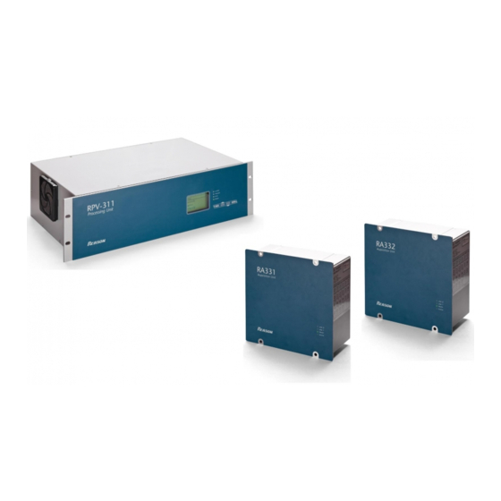
- Page 10 TABLE OF FIGURES Figure 1: Functional design overview Figure 2: RA333, RA332, RA333 and RPV311 Figure 3: Front View of the RPV311 Figure 4: Back view of the RPV311 Figure 5: Front and back views of the RA331 Figure 6: Front and back views of the RA332 Figure 7: Front and back views of the RA333 Figure 8: Initial configuration screen Figure 9: Equipment identification configuration section...
- Page 11 Figure 33: Disturbance recorder – trigger’d recording configuration Figure 34: Disturbance recorder – continuous recording configuration section Figure 35: Traveling waves recorder – trigger’d recording configuration section Figure 36: Steady-state recorder – average series configuration section Figure 37: Steady-state recorder – harmonics configuration section Figure 38: Steady-state recorder –...
- Page 12 Figure 70: Concatenation event example Figure 71: Example of an event without concatenation Figure 72 – TW Fault Locator architecture overview Figure 73 - Typical Circuit Three-Terminal Application Figure 74 – Three terminal line application Figure 75 – TW Fault Location example 1 Figure 76 - TW Fault Location example 2 Figure 77: Directory of the records received of the equipment Figure 78: Configuration Tool main screen...
- Page 13 Figure 105: AC/DC power connection Figure 106: AC/DC power connection Figure 107: RPV311 Grounding Figure 108: RA33X Grounding Figure 109: RPV311 Fiber Optic Connectors Figure 110: RA331, RA332 and RA333 fiber optic connectors Figure 111: Connection between RPV311 and the RA331, RA332 or RA333 Figure 112: Screws of the Back Panel Figure 113: Analog input terminals Figure 114: Screws of the Back Panel...
- Page 14 Figure 141: RPV311 Dimensions Figure 142: RA331, RA332 and RA333 dimensions Figure 143: AEMC / MN312 (PN 2468) current clamps...
-
Page 15: Chapter 1 Introduction
INTRODUCTION CHAPTER 1... -
Page 16: Chapter Overview
Chapter 1 – Introduction RPV311 CHAPTER OVERVIEW This chapter provides some general information about the technical manual and an introduction to the device(s) described in this technical manual. THIS CHAPTER CONTAINS THE FOLLOWING SECTIONS: Foreword Product Scope Features and Functions Unpacking External Indication Key Features... -
Page 17: Foreword
Some of these terms are well-known industry-specific terms while others may be special product-specific terms used by Alstom Grid. The first instance of any acronym or term used in a particular chapter is explained. In addition, a separate glossary is available on the Alstom website, or from the Alstom contact centre. - Page 18 Chapter 1 – Introduction RPV311 DFR - DataFlex file extension; EMC - Electromagnetic Compatibility; FRQ - Frequency; FUT - Firmware Upgrade Tool; GOOSE - Generic Object Oriented Substation Events; GPS - Global Positioning System; HDD - Hard disk drive; HTML - HyperText Markup Language; IMB - Imbalance;...
- Page 19 Chapter 1 – Introduction RPV311 SQL - Structured Query Language; SSD - Solid-state Drive; TCP - Transmission Control Protocol; THD - Total harmonic distortion; TTL - Time to Live; TW - Travelling Wave; UDP - User Datagram Protocol; UTC - Coordinated Universal Time; VLAN - Virtual Local Area Network;...
-
Page 20: Product Scope
Chapter 1 – Introduction RPV311 PRODUCT SCOPE The processing unit RPV311 and the acquisition modules RA331, RA332, and RA333 offer a distributed solution for Multifunction Digital Recording. The solution is designed for the acquisition, monitoring and recording of electrical quantities normally associated with electrical power generation, transmission or distribution equipment. -
Page 21: Unpacking
Unpack the equipment carefully and make sure that all accessories and cables are put away so they will not be lost. Check the contents against the packing list. If any of the contents listed is missing, please contact Alstom immediately (see contact information at the beginning of this manual). -
Page 22: External Indication
Chapter 1 – Introduction RPV311 EXTERNAL INDICATION RPV311 NAMEPLATE Information about the company, power supply and the serial number and part number is shown on a small nameplate affixed to the rear of the equipment, as shown in Figure Figure 1: Location of Serial Number, Part Number and specifications RA331, RA332, AND RA333 NAMEPLATE Information about the company, power supply, the serial number and part number and specifications about the equipment are shown on a small nameplate affixed to the side of the equipment, as shown in... - Page 23 Chapter 1 – Introduction RPV311 Figure 2: Location of Serial Number, Part Number and specifications RPV311-TM-EN-6...
-
Page 24: Key Features
Chapter 1 – Introduction RPV311 KEY FEATURES The RPV311 plus RA33x acquisition modules solution presents the following key features: Acquisition system: 16-bit opto-isolated analog-to-digital converters, independent for each channel (50/60 Hz channels); 256 points-per-cycle sampling rate (50/60 Hz channels); Frequency response of DC to 3.0 kHz;... - Page 25 Chapter 1 – Introduction RPV311 RS232 serial port for modem connection; Support for IEC 61850: Up to 320 binary inputs related to IEC 61850-8-1 GOOSE messages (optional); Two Ethernet ports for redundant connection (optional); One Ethernet port for Process Bus (IEC 61850-9-2LE Sampled Values) connection (optional).
-
Page 26: Compliance
Chapter 1 – Introduction RPV311 COMPLIANCE The device has undergone a range of extensive testing and certification processes to ensure and prove compatibility with all target markets. A detailed description of these criteria can be found in the Technical Specifications chapter. RPV311-TM-EN-6... -
Page 27: Functional Overview
Chapter 1 – Introduction RPV311 FUNCTIONAL OVERVIEW The processing unit RPV311 and the acquisition modules RA331, RA332, and RA333 offer a distributed solution for Multifunction Digital Recording. The solution is designed for the acquisition, monitoring and recording of electrical quantities normally associated with electrical power generation, transmission or distribution equipment. -
Page 28: Programs Under The Gpl 2 License
Chapter 1 – Introduction RPV311 PROGRAMS UNDER THE GPL 2 LICENSE The RPV311 uses GPL 2 licenses in its implementation. In case the user wants get ahold of the source code, please contact out contact centre. RPV311-TM-EN-6... -
Page 29: Ordering Options
Chapter 1 – Introduction RPV311 ORDERING OPTIONS 10.1 RPV311 Variants Order Number 7 8 9-11 12 13-14 15 Model Type RPV311 Multifunction Recorder IED RPV311 Power Supply 24-48 Vdc 100-250 Vdc / 110-240 Vac Network Interface Two RJ45 copper 100BASE-TX Ethernet interfaces Two RJ45 copper or duplex ST-type connector 100BASE-X Ethernet interfaces Functions and Protocols Fault Recorder... -
Page 30: Ra331
Chapter 1 – Introduction RPV311 10.2 RA331 Variants Order Number 6 7 8 9 10 11 12 Model Type RA331 Acquisition Module for RPV311 RA331 Power Supply 24-48 Vdc 100-250 Vdc / 110-240 Vac Analogue Inputs 1 to 4 Voltage inputs 115 V / Current inputs 1 A; full-scale 20 A (Ith = 32 A) Voltage inputs 115 V / Current inputs 5 A;... -
Page 31: Ra332
Chapter 1 – Introduction RPV311 10.3 RA332 Variants Order Number 6 7 8 9 Model Type RA33 RA332 Acquisition Module for RPV311 Power Supply 24-48 Vdc 100-250 Vdc / 110-240 Vac Analogue Inputs 1 to 4 Voltage inputs 115 V / Current inputs 1 A; full-scale 20 A (Ith = 32 A) Voltage inputs 115 V / Current inputs 5 A;... - Page 32 Chapter 1 – Introduction RPV311 250 V Not installed Digital Inputs 17 to 32 24 V / 48 V 125 V 250 V Not installed Customization / Regionalisation Default Reason branding Hardware Design Suffix Third version Issue B RPV311-TM-EN-6...
-
Page 33: Ra333
Chapter 1 – Introduction RPV311 10.4 RA333 Variants Order Number 6 7 8 9 10 11 12 13 Model Type RA333 Travelling Wave and DFR Acquisition Module for RPV311 RA333 Power Supply 24-48 Vdc 100-250 Vdc / 110-240 Vac Analogue Inputs 1 to 4 Voltage inputs 115 V / Current inputs 1 A;... -
Page 34: Chapter 2 Safety Information
SAFETY INFORMATION CHAPTER 2... -
Page 35: Chapter Overview
Chapter 2 – Safety Information RPV311 CHAPTER OVERVIEW This chapter provides information about the safe handling of the equipment. The equipment must be properly installed and handled in order to maintain it in a safe condition and to keep personnel safe at all times. You must be familiar with information contained in this chapter before unpacking, installing, commissioning, or servicing the equipment. -
Page 36: Health And Safety
Chapter 2 – Safety Information RPV311 HEALTH AND SAFETY Personnel associated with the equipment must be familiar with the contents of this Safety Information. When electrical equipment is in operation, dangerous voltages are present in certain parts of the equipment. Improper use of the equipment and failure to observe warning notices will endanger personnel. -
Page 37: Symbols
Chapter 2 – Safety Information RPV311 SYMBOLS Throughout this manual you will come across the following symbols. You will also see these symbols on parts of the equipment. Caution: Refer to equipment documentation. Failure to do so could result in damage to the equipment Risk of electric shock Ground terminal. -
Page 38: Installation, Commissioning And Servicing
Chapter 2 – Safety Information RPV311 INSTALLATION, COMMISSIONING AND SERVICING LIFTING HAZARDS Many injuries are caused by: Lifting heavy objects Lifting things incorrectly Pushing or pulling heavy objects Using the same muscles repetitively Plan carefully, identify any possible hazards and determine how best to move the product. Look at other ways of moving the load to avoid manual handling. -
Page 39: Fusing Requirements
Chapter 2 – Safety Information RPV311 Testing may leave capacitors charged to dangerous voltage levels. Discharge capacitors by reducing test voltages to zero before disconnecting test leads. If the equipment is used in a manner not specified by the manufacturer, the protection provided by the equipment may be impaired. -
Page 40: Equipment Connections
Chapter 2 – Safety Information RPV311 Reason devices contain an internal fuse for the power supply which is only accessed by opening the product. This does not remove the requirement for external fusing or use of an MCB as previously mentioned. The ratings of the internal fuses are: RPV unit: 5 Amp, type T, 250V rating RA units: 2 Amp, type T, 250V rating CTs must NOT be fused since open circuiting them may produce lethal hazardous voltages. -
Page 41: Pre-Energisation Checklist
Chapter 2 – Safety Information RPV311 The PCT connection must have low-inductance and be as short as possible. For best EMC performance, ground the unit using a 10 mm (0.4 inch) wide braided grounding strap. All connections to the equipment must have a defined potential. Connections that are pre- wired, but not used, should be earthed, or connected to a common grouped potential. -
Page 42: Upgrading/Servicing
Chapter 2 – Safety Information RPV311 Operation of computers and equipment connected to RPV311 and RA33x under environmental conditions such as temperature and humidity that exceed the conditions specified in their respective manuals can cause malfunctioning or even irreversible damage to them or the nearby installation. -
Page 43: Decommissioning And Disposal
Chapter 2 – Safety Information RPV311 DECOMMISSIONING AND DISPOSAL Before decommissioning, completely isolate the equipment power supplies (both poles of any dc supply). The auxiliary supply input may have capacitors in parallel, which may still be charged. To avoid electric shock, discharge the capacitors using the external terminals before decommissioning. -
Page 44: Standards Compliance
Chapter 2 – Safety Information RPV311 STANDARDS COMPLIANCE Compliance with the European Commission Directive on EMC and LVD is demonstrated using a Technical File. EMC COMPLIANCE: Compliance with IEC 60255-26:2013 was used to establish conformity. PRODUCT SAFETY: 2006/95/EC Compliance with IEC 61010-1:2010 was used to establish conformity. PROTECTIVE CLASS Protective Class 1. -
Page 45: Chapter 3 Hardware Design
HARDWARE DESIGN CHAPTER 3... -
Page 46: Chapter Overview
Chapter 3 – Hardware Design RPV311 CHAPTER OVERVIEW This chapter provides information about the product's hardware design. THIS CHAPTER CONTAINS THE FOLLOWING SECTIONS: Hardware Architecture Mechanical Implementation RPV311-TM-EN-6... -
Page 47: Hardware Architecture
Chapter 3 – Hardware Design RPV311 HARDWARE ARCHITECTURE The RPV311 is a multifunction processing unit and has an acquisition system with 16-bit A/D D converters that provide an acquisition rate of 256 points-per-cycle synchronized by the IRIG-B signal. It has a high processing capability, which allows the acquisition of up to 64 analog channels and 256 digital channels divided in up to 8 acquisition modules connected by fiber-optic links. - Page 48 Chapter 3 – Hardware Design RPV311 Device Logic Demand (slots) RA331 RA332 RA333 DFR RA333 TW The user can combine the RA units as long as the logical sum of the slots value of each RA do not exceed the maximum number of 12. Note: Differently from the RA331/332 the RA333 has two link: One for the DFR functionality and another for the TW functionality.
-
Page 49: Mechanical Implementation
Chapter 3 – Hardware Design RPV311 MECHANICAL IMPLEMENTATION RPV311 3.1.1 MAIN FEATURES Fan-less and no rotating part design Trigger waveform recorder at 256, 128, or 64 points-per-cycle; Continuous waveform recorder at 16 points-per-cycle; Continuous disturbance recorder and trigger recorder (optional); ... -
Page 50: Figure 3: Front View Of The Rpv311
Chapter 3 – Hardware Design RPV311 3.1.2 COMPONENTES Front view of the RPV311, showing all the main components on the front panel. Figure 3: Front View of the RPV311 Indicators of the state of the equipment: Alarm: Lights up when the equipment requires attention of the operator. Trigger: Flashes when a threshold has been triggered;... -
Page 51: Ra331
2 electrical Ethernet interfaces for the communication between the equipment. 1 electrical Ethernet interface for the Process Bus communication. Double internal converter for optical Ethernet interface. Serial port RS323 for modem connection. Maintenance ports for exclusive use by Alstom's technical support personnel. RA331 3.2.1 MAIN FEATURES ... -
Page 52: Ra332
Chapter 3 – Hardware Design RPV311 Figure 5: Front and back views of the RA331 AC or DC power input. Mains and Ready back panel indicators: The Mains is lit when the module is powered. Ready indicator lights up after the module self-test is completed. Up to 8 analog inputs for voltage, current, or DC transducers, identified as 101 to 108. -
Page 53: Figure 6: Front And Back Views Of The Ra332
Chapter 3 – Hardware Design RPV311 Figure 6: Front and back views of the RA332 AC or DC power input. Mains and Ready back panel indicators: Mains is lit when the module is powered-up. Ready indicator lights up after the module self-test is completed. Up to 16 analog inputs for voltage, current, or DC transducers, identified as 101 to 116. -
Page 54: Ra333
Chapter 3 – Hardware Design RPV311 RA333 3.4.1 KEY FEATURES 3 high-speed analog inputs with 5 MHz; Up to 8 analog inputs with 50/60 Hz (voltage, current, DC transducers); Up to 32 digital inputs; 16-bit analog-to-digital converters, 256 points-per-cycle sampling rate for 50/60 Hz acquisition; ... - Page 55 Chapter 3 – Hardware Design RPV311 The Ready indicator lights up after the module's self-test is completed; The Mains indicator lights up when the module is powered; The PPS indicator flashes signaling that the timing signal of the processing module is detected; The Busy indicator lights up when a traveling wave signal is detected and the RA333 is transmitting the data for processing module.
-
Page 57: Chapter 4 Configuration
CONFIGURATION CHAPTER 4... -
Page 58: Chapter Overview
Chapter 4 – Configuration RPV311 CHAPTER OVERVIEW This chapter includes concise instructions of how to configure all available features in the device. THIS CHAPTER CONTAINS THE FOLLOWING SECTIONS: Accessing the Equipment Configuration Equipment Voltage Circuit Power Circuit Digital Channels DC Channels Threshold Fault Records Disturbance Recorder... -
Page 59: Accessing The Equipment Configuration
Chapter 4 – Configuration RPV311 ACCESSING THE EQUIPMENT CONFIGURATION Access to the equipment's configuration is provided by the Web Interface. When the equipment is accessed, a copy of the current configuration is maintained on the equipment until a new configuration is sent. To enter the configuration interface, click on the <C >... -
Page 60: Configuration History
Chapter 4 – Configuration RPV311 D To send the changes to the equipment, click on the <T > button. Before sending the configuration RANSMIT to the equipment, the user must define the changes to be included in the configuration history. By clicking the <O >... -
Page 61: Equipment
Chapter 4 – Configuration RPV311 EQUIPMENT IDENTIFICATION On this screen, shown below, it is possible to configure the equipment identifier, location and owner. These three fields make up the equipment file name pursuant to the COMNAME rule. The equipment identification will appear in the name of the records; therefore, it is very important that it be properly identified. -
Page 62: Synchronization
Chapter 4 – Configuration RPV311 SYNCHRONIZATION If the IRIG-B signal has the CF extensions (IEEE1344), timing information as date, hour, year, time zone and daylight saving time can be provided by the signal. Time zone and daylight saving time information can also be manually set via the Web Interface, overriding the information of the IRIG-B signal. -
Page 63: Communications
Chapter 4 – Configuration RPV311 COMMUNICATIONS The RPV311 communication may be via Ethernet and serial ports. The equipment may also operate as a gateway over a local subnet. Optionally the user can choose between two types of Ethernet, optical and electrical. Gateway setup will enable the RPV311 to communicate with other equipment connected over a local subnetwork. -
Page 64: Figure 11: Equipment Serial Port Configuration Section
Chapter 4 – Configuration RPV311 The RPV311 allows point-to-point communication with a conventional modem, cellular phone, GPRS and radio links. The Serial Port can be configured by accessing the section shown in Figure Figure 11: Equipment serial port configuration section A The B scroll box allows user to select the data bits (7 or 8), parity (none, even or odd) and stop PARITY... -
Page 65: Acquisition With Remote Acquisition Modules
Chapter 4 – Configuration RPV311 ACQUISITION WITH REMOTE ACQUISITION MODULES The RPV311 data acquisition can be performed by the RA331, RA332 and RA333 remote acquisition modules. The RA333 module consists of two different acquisition systems. One, called DFR, is used for analog data acquisition of 50/60 Hz of voltage, current, or DC. -
Page 66: Figure 12: Links Between Rpv And Acquisition Modules Configuration Section
Chapter 4 – Configuration RPV311 Figure 12: Links between RPV and acquisition modules configuration section A The Position represents the position where the acquisition module is physically connected to the RPV311. Positions A to L. B The Module scroll box allows user to select the acquisition module used in the link and its characteristics based on the Part Number of the module. -
Page 67: Acquisition With Sampled Values
Chapter 4 – Configuration RPV311 To improve the accuracy of the measurement, a correction factor can be manually provided. Inputs without the correction factor have accuracy better than 1%. The digital channels do not have type selection. Figure 13: Analog inputs configuration section A The P indicates the position of each analog input on the back panel of the module. -
Page 68: Figure 14: Sampled Values Subscriptions Links Configuration Section
Chapter 4 – Configuration RPV311 The RPV311 processing module can be configured with up to 8 Subscription links. To configure the links, access the S section, shown in Figure AMPLED VALUES SUBSCRIPTIONS Figure 14: Sampled Values subscriptions links configuration section A The E check box allows user to enable the Subscription link feature. -
Page 69: Access Control
Chapter 4 – Configuration RPV311 Figure 15: Analog inputs configuration section for Sampled Values channels A The P indicates the position of each analog input according to the Sampled Value message. OSITION B The I scroll box allows user to select the type of the signal to be received as Sampled Values. NPUT C The A text field allows user to enter a correction factor to adjust the accuracy of the... -
Page 70: User
Chapter 4 – Configuration RPV311 Figure 16: Equipment access control configuration section A The U check box enables use of password to access equipment SE PASSWORD FOR ALL ACCESS LEVELS operation and configuration via Web Interface. B The F text field allows user to enter an independent password to update the IRMWARE UPDATE PASSWORD firmware for the equipment. -
Page 71: Figure 17: Adding New User Section
Chapter 4 – Configuration RPV311 Figure 17: Adding new user section A The U text field allows entering a user identification (maximum 8 characters). No editing is allowed. B The N text field allows user to enter a new password to access the Web Interface (maximum ASSWORD 8 characters). -
Page 72: Record Management
Chapter 4 – Configuration RPV311 Figure 18: Changing the administrator password section: Changing the administrator password section A The O text field allows user to enter an old password. ASSWORD B The N text field allows user to enter a new password to access the Web Interface (maximum ASSWORD 8 characters). -
Page 73: Auto Upload
Chapter 4 – Configuration RPV311 Figure 19: Record management configuration section A Selecting the A check box, erases older record automatically if memory capacity exceeds 90%. UTO ERASE B The E scroll box allows user to choose a type of record (fault, disturbance, steady-state and SOE) RASE ALL to be removed. -
Page 74: Figure 20: Auto Upload Configuration Section
Chapter 4 – Configuration RPV311 Figure 20: Auto upload configuration section A The D check box allows user to select a record destination IP address previously entered. ESTINATION B Selecting the F SOE check boxes, these records AULT ISTURBANCE TEADY TATE RAVELING AVE OR... -
Page 75: Figure 21: Email/Fax Configuration
Chapter 4 – Configuration RPV311 Figure 21: Email/Fax configuration RPV311-TM-EN-6... -
Page 76: Voltage Circuit
Chapter 4 – Configuration RPV311 VOLTAGE CIRCUIT Considering the input type configurations, it is possible to create voltage circuits with 1, 2, 3, or 4 elements. For details about each circuit type, see Chapter 14. The circuit sequences supported by the equipment are ABC, BCA, CAB, CBA, BAC, and CBA and may be customized by the user in the equipment setup. -
Page 77: Figure 22: Adding And Editing Voltage Circuits
Chapter 4 – Configuration RPV311 Figure 22: Adding and editing voltage circuits RPV311-TM-EN-6... -
Page 78: Current Circuits
Chapter 4 – Configuration RPV311 CURRENT CIRCUITS Considering the input type configurations, it is possible to create current circuits with 1, 2, 3, or 4 elements. For details about the each circuit type, see Chapter 14 Installation. The phase sequences of the circuits supported by the equipment are ABC, BCA, CAB, CBA, BAC, and CBA and may be customized by the user in the Equipment Setup, shown in Section 3.9. -
Page 79: Figure 23: Adding And Editing Current Circuits
Chapter 4 – Configuration RPV311 Figure 23: Adding and editing current circuits A The <R > button allows user to rename the circuit. ENAME B The <R > button allows user to delete the circuit. EMOVE RPV311-TM-EN-6... -
Page 80: Power Circuit
Chapter 4 – Configuration RPV311 POWER CIRCUIT Power circuits can be created of circuit voltage and current. To add a new power circuit select the P section and fill in the following: OWER IRCUITS The I text field allows user to enter a single code for the circuit being defined (maximum 12 DENTIFIER characters). -
Page 81: Digital Channels
Chapter 4 – Configuration RPV311 DIGITAL CHANNELS The acquisition is simultaneous and synchronized with a time resolution of 65.104 ��s at 60 Hz or 78.125 ��s at 50 Hz. The polarity is user-programmable (active high, active low). Digital channels can be associated with physical electrical digital inputs or associated with the detection of IEC61850 GOOSE messages. -
Page 82: Figure 25: Adding And Editing Digital Channels
Chapter 4 – Configuration RPV311 Figure 25: Adding and editing digital channels The <R > button allows user to rename the digital channel. ENAME The <R > button allows user to delete the digital channel. EMOVE RPV311-TM-EN-6... -
Page 83: Dc Channels
Chapter 4 – Configuration RPV311 DC CHANNELS The signal of the transducer (±10 V or 0-20 mA) is converted in to the desired physical measurement using a first order transfer function with the parameters of gain (��) and offset (��) defined by the user: ��... -
Page 84: Figure 26: Adding And Editing Dc Channels
Chapter 4 – Configuration RPV311 Figure 26: Adding and editing DC channels The <R > button allows user to rename the DC channel. ENAME The <R > button allows user to delete the DC channel. EMOVE RPV311-TM-EN-6... -
Page 85: Thresholds
Chapter 4 – Configuration RPV311 THRESHOLDS Measured values are continuously monitored and may be tested once every cycle of the nominal frequency of the system, against lower and upper thresholds and range rates involving: Magnitude; Frequency; Active, Reactive, and Apparent Powers; Positive and Negative Sequences;... -
Page 86: Adding New Voltage Thresholds
Chapter 4 – Configuration RPV311 DC Transducers: upper and lower limits; Digital channels: "L" to "H" transition, "H" to "L" transition, "H" and "L" level.; Following parameters can be set for every defined threshold: Parameters set for every defined threshold 0 …... -
Page 87: Adding New Current Thresholds
Chapter 4 – Configuration RPV311 The O scroll box allows user to select greater than or less than for analog magnitude; PERATOR The V text field allows user to enter the magnitude value associated with greater than or less than ALUE operator;... - Page 88 Chapter 4 – Configuration RPV311 The S scroll box allows user to define a code of a current circuit used. No editing allowed; OURCE The Q scroll box allows user to select the associated magnitude to be monitored. For current circuits: UANTITY ABC and N - magnitude or effective value;...
-
Page 89: Adding New Power Thresholds
Chapter 4 – Configuration RPV311 Figure 28: Adding and editing a current threshold A The <A > button allows user to apply the hold time or the hysteresis for all thresholds. PPLY ALL B The <R > button allows user to delete the threshold. EMOVE ADDING NEW POWER THRESHOLDS To add a power threshold, fill in the following:... -
Page 90: Figure 29: Adding And Editing A Power Threshold
Chapter 4 – Configuration RPV311 The O scroll box allows user to select greater than or less than for analog magnitude. PERATOR The V text field allows user to enter the magnitude value associated with greater than or less ALUE than operator. - Page 91 Chapter 4 – Configuration RPV311 Power Swing,Voltage Oscillation and Frequency Oscillation The parameters that are configurable in Power Swing,Voltage Oscillation and Frequency Oscillation threshold are: Oscillation magnitude (in MVA, PU and Hz), Oscillation time (in seconds) and Hysteresis (in percentage).
-
Page 92: Adding New Digital Thresholds
Chapter 4 – Configuration RPV311 ADDING NEW DIGITAL THRESHOLDS To add a digital threshold, fill in the following: The S scroll box allows user to define a code of a digital channel used. No editing allowed; OURCE The C scroll box allows user to select the threshold condition: ONDITION (blank) -
Page 93: Figure 30: Adding And Editing A Dc Threshold
Chapter 4 – Configuration RPV311 Figure 30: Adding and editing a DC threshold A The <A > button allows user to apply the hold time or the hysteresis for all threshold. PPLY ALL B The <R > button allows user to delete the threshold. EMOVE RPV311-TM-EN-6... -
Page 94: Fault Recorder
Chapter 4 – Configuration RPV311 FAULT RECORDER The RPV311 allows user to register triggered and continuous fault recorder. TRIGGER’D RECORDING 10.1 In this section, shown in Figure 31, it is possible to configure the equipment's fault triggered recorder. Figure 31: Fault recorder – triggered recording configuration section A The E check box allows user to enable the fault recorder feature. -
Page 95: Continuous Recording
Chapter 4 – Configuration RPV311 C The T field contains all the thresholds created. The logic equation uses AND and OR logic RIGGER LOGIC operators over previously defined thresholds. Initially, all preset thresholds are displayed as implicit OR operators, one per line. To enable thresholds individually, click on the threshold and select E NABLE To disable discarded thresholds individually, click on the threshold and select D... - Page 96 Chapter 4 – Configuration RPV311 A The E check box allows user to enable the continuous fault recording feature. NABLED B The Q scroll box allows user to select the derived quantity of continuous disturbance records. UANTITY C The <D >...
-
Page 97: Disturbance Recorder
Chapter 4 – Configuration RPV311 DISTURBANCE RECORDER The RPV311 allows user to configure triggered and continuous disturbance recording. 11.1 TRIGGER'D RECORDING In this section, shown in Figure it is possible to configure the equipment disturbance triggered recorder. Figure 33: Disturbance recorder – trigger’d recording configuration A The E check box allows user to enable the disturbance triggered recorder feature. -
Page 98: Continuous Recording
Chapter 4 – Configuration RPV311 To enable thresholds individually, click on the threshold and select E NABLE To disable discarded thresholds individually, click on the threshold and select D ISABLE To break or remove complex thresholds, click on the threshold and select C UT LAST ... - Page 99 Chapter 4 – Configuration RPV311 A The E check box allows user to enable the continuous disturbance reordering feature. NABLED B The D scroll box allows user to select the derived quantity of continuous disturbance ERIVED QUANTITY records. C The <D >...
-
Page 100: Traveling Waves Recorder
Chapter 4 – Configuration RPV311 TRAVELING WAVES RECORDER The RPV311 allows user to configure a traveling wave recorder for fault location, by trigger. To start the configuration, it is necessary add a new recorder in accordance with the position of selected links in equipment. -
Page 101: Recommended Sources Of Trigger
Chapter 4 – Configuration RPV311 Click on the threshold to which is desired to add the previously selected threshold and then select the threshold to be added. D Selecting the R or S check box enables ECEIVE THERNET CROSS TRIGGER THERNET CROSS TRIGGER these features. -
Page 102: Steady-State
Chapter 4 – Configuration RPV311 STEADY-STATE RPV311 allows user to register average series, harmonics, and flicker in the steady-state recorder. 13.1 AVERAGE SERIES In this section, shown in Figure 36, it is possible to configure the equipment's average series recorder. The average series the following voltage and current circuits quantities: magnitude or effective value, neutral magnitude or effective value, frequency, unbalance and total harmonic distortion. -
Page 103: Flicker
Chapter 4 – Configuration RPV311 Figure 37: Steady-state recorder – harmonics configuration section A The I field shows all the circuits previously configured. DENTIFIER B The T field shows the circuit type. C The check box allows the selection of preset circuits for the steady-state record formation. In the harmonics recorder, only 2 circuits can be selected at the same time. -
Page 104: Figure 38: Steady-State Recorder - Flicker Configuration Section
Chapter 4 – Configuration RPV311 Figure 38: Steady-state recorder – flicker configuration section A The I field shows all the voltage circuits previously configured. DENTIFIER B The T field shows the circuit type. C The check box allows the selection of circuits to be included in the steady-state record. In the flicker recorder, up to 6 circuits can be selected at the same time. -
Page 105: Groups
Chapter 4 – Configuration RPV311 GROUPS Group setup allows the user to monitor voltage and current circuit information via local interface or the Monitoring screen at the web interface operation. It is not possible to monitor circuits that are not included in either group. To add new groups fill in the following: ... -
Page 106: Relays
Chapter 4 – Configuration RPV311 RELAYS Relays indicate events or state transitions and set off the alarm on the equipment. RPV311 provides four relays: three relays set by the user and one factory default relay, which signals internal equipment failure. 15.1 ON TIME In this section, shown in... -
Page 107: Figure 41: Relay Signaling Events Configuration Section
Chapter 4 – Configuration RPV311 Figure 41: Relay signaling events configuration section A The L events text field allows user to enter a code used for signaling events. Refer to Chapter 5 for log references. Signaling is only during the time set in the previous section. B The W check box allows user to select the following events for signaling: ARNINGS... -
Page 108: Pmu
Chapter 4 – Configuration RPV311 Synchrophasors are measured and broadcast according to the specifications contained in IEEE C37.118, Standard for Synchrophasors for Power Systems. For further information about the PMU, see Chapter 8. The PMU functionality is able to send up to 4 streams of data and the configuration is divided in two sub menus.: Data;... - Page 109 Chapter 4 – Configuration RPV311 In Spontaneous mode the RPV sends the PMU data automatically up to 4 different socket addresses (IP + port number). The 4 streams of data can be sent using unicast or multicast transmission. The parameters of the Communication screen are listed below: <C >...
-
Page 110: Modbus
Chapter 4 – Configuration RPV311 MODBUS Status, analog and digital data are available in MODBUS registers. Access to SCADA integration is provided over the Ethernet interface. Up to 8 simultaneous connections are allowed a maximum rate of 60 accesses per second. For further information about MODBUS, see Chapter 9 Each register reports 16-bit data. - Page 111 Chapter 4 – Configuration RPV311 A The E check box allows user to enable recording. NABLE B The A field allows user to select a derived quantity and insert a decimal correction factor of an NALOG DATA analog input. C The D field allows user to select a block of a digital input.
-
Page 112: Dnp3
Chapter 4 – Configuration RPV311 DNP3 The DNP3 functionality is fully associated with the MODBUS functionality in the RPV311. To use the DNP3 protocol, it is necessary to insert a configuration key at the equipment to unlock the MODBUS and DNP3 functionalities. - Page 113 Chapter 4 – Configuration RPV311 Channel name RA33x input Channel type DNP3 Database associated number A201 Physical A217 Physical C201 Physical D_Linha2 B201 Physical D_Linha3 B202 Physical GOOSE GOOSE A210 Physical A211 Physical A212 Physical 18.2.2 ADDING ANALOG CHANNELS The analog data possibilites for the DNP3 communication procol are the same as for MODBUS. The MODBUS analog data are shown in section 2.3.
-
Page 114: Figure 44: Analog Channels Selected
Chapter 4 – Configuration RPV311 Figure 44: Analog channels selected A The field is only used for analog quantities with DNP3; B Used to configure the digital inputs that will be sent. RPV311-TM-EN-6... - Page 115 Chapter 4 – Configuration RPV311 Data name MODBUS DNP3 Database Data type register associated number number Alarms: bit 0: Equipment NOK bit 1: Primary power failure bit 2: Not used bit 3: Not used bit 4: Equipment not synchronized bit 5: Fault recorder low memory bit 6: Disturbance recorder low memory bit 7: Steady-state recorder low memory bit 8: SOE recorder lack of memory...
- Page 116 Chapter 4 – Configuration RPV311 Note: The phase angles are sent in degrees for the MODBUS and radian for DNP3 RPV311-TM-EN-6...
-
Page 117: Chapter 5 Operation
OPERATION CHAPTER 5... -
Page 118: Chapter Overview
Chapter 5 – Operation RPV311 CHAPTER OVERVIEW This chapter provides information on possible ways to access and operate the device. . THIS CHAPTER CONTAINS THE FOLLOWING SECTIONS: Local Interface Monitoring Web Interface RPV311-TM-EN-6... -
Page 119: Local Interface
Chapter 5 – Operation RPV311 LOCAL INTERFACE The RPV311 has a local interface for human-machine interaction, composed of a display, navigation buttons, and status indicators, as shown in the figure below. Figure 45: Local interface of the RPV311 STATUS INDICATORS The local interface has 4 status indicators: ... - Page 120 Chapter 5 – Operation RPV311 Date and time; If the equipment is in normal operation; If the equipment is using the IRIG-B timing and the signal quality; Internal temperature; Date and time since last power up; ...
-
Page 121: Figure 46: Status Monitoring Sequence
Chapter 5 – Operation RPV311 Figure 46: Status monitoring sequence RPV311-TM-EN-6... - Page 122 Chapter 5 – Operation RPV311 2.3.2 MONITORING It is possible to locally monitor the analog quantities measured by the RPV311. Quantities are separated by the name of the circuit and the data is updated once per second. To view the values related to quantities associated with a circuit, select the circuit group, choose the circuit type (voltage, current, or power) and then select the name of the circuit to be monitored.
-
Page 123: Figure 47: Monitoring Sequence
Chapter 5 – Operation RPV311 Figure 47: Monitoring sequence RPV311-TM-EN-6... - Page 124 Chapter 5 – Operation RPV311 2.3.3 RECORDS This menu shows the list of records provided by the equipment in decreasing chronological order (of the latest to the oldest). To view a record, select the type of the record (Waveform, Synchrophasors, Steady-state, TW or SOE), and then select the date and the time of the record to be viewed.
-
Page 125: Figure 48: Records Monitoring Sequence: Fault Disturbance, Tw And Average Series
Chapter 5 – Operation RPV311 Figure 48: Records monitoring sequence: Fault disturbance, TW and average series RPV311-TM-EN-6... -
Page 126: Figure 49: Records Monitoring Sequence: Harmonics, Flicker And Soe
Chapter 5 – Operation RPV311 Figure 49: Records monitoring sequence: harmonics, flicker and SOE RPV311-TM-EN-6... - Page 127 Chapter 5 – Operation RPV311 2.3.4 SETTINGS Shows the RPV311 configuration, related to: Equipment identification; Synchronization information; Communication settings (gateway, serial port and Ethernet); Information about voltage, current and power circuits and digital channels; Relay configuration. To access the Setting items, use the sequence shown in Figures 51 to 53.
-
Page 128: Figure 50: Equipment Settings Monitoring Sequence
Chapter 5 – Operation RPV311 Figure 50: Equipment settings monitoring sequence RPV311-TM-EN-6... -
Page 129: Figure 51: Circuit And Channel Settings Monitoring Sequence
Chapter 5 – Operation RPV311 Figure 51: Circuit and channel settings monitoring sequence RPV311-TM-EN-6... -
Page 130: Figure 52: Relays, Pmu And Modbus Settings Monitoring Sequence
Chapter 5 – Operation RPV311 Figure 52: Relays, PMU and MODBUS settings monitoring sequence RPV311-TM-EN-6... - Page 131 Chapter 5 – Operation RPV311 2.3.5 GENERAL INFORMATION Shows general information about the equipment, such as: Equipment model; Processor; Module identification; Frequency; Type of sequence; Key (to enable the equipment functions); Features (features enabled). To access the items of General Information, use the sequence shown in Figure 53.
-
Page 132: Figure 53: General Information Monitoring Sequence
Chapter 5 – Operation RPV311 Figure 53: General information monitoring sequence RPV311-TM-EN-6... -
Page 133: Monitoring Web Interface
Chapter 5 – Operation RPV311 MONITORING WEB INTERFACE ACCESSING THE MONITORING WEB INTERFACE The equipment’s monitoring interface allows access to the equipment and link status, event log, manual trigger, records, monitoring of magnitudes, configuration history, and general information about the equipment. - Page 134 Chapter 5 – Operation RPV311 in order to verify the support applications and the minimum requirements needed to access all the RPV311 Web Interface features. To access the monitoring interface, enter the equipment's Ethernet IP in a web browser. If the Flash Player 9.0 (or higher) plug-in is not already installed on the computer, it will be automatically installed by the operating system.
-
Page 135: Navigating
Chapter 5 – Operation RPV311 If the equipment is not fond with the default IP settings, refer to Chapter 5 in order to be able to verify the current IP address. NAVIGATING The default screen of the Web Interface is shown in Figure 54. -
Page 136: Status
Chapter 5 – Operation RPV311 To finish the session, click on the <L > button. A confirmation box will appear. Click Yes to confirm or OGOUT No to keep logged in. If the screen is closed before pressing the logout button, the user will remain connected until a time delay expires (1 minute). -
Page 137: Figure 56: Link Status Screen
Chapter 5 – Operation RPV311 Memory usage: indicates the memory usage related to the fault, disturbance, TW, steady-state and SOE records and log; Last power-up: indicates the date and time since the last power up. B The <R >... -
Page 138: Log
Chapter 5 – Operation RPV311 The Log screen, shown in Figure 57, displays a history of equipment event logs. Figure 57: Log screen A The Search box allows user to choose the period of time of the oldest to the latest to display. B The Codes box allows user to search for specific logs or time intervals. -
Page 139: Records
Chapter 5 – Operation RPV311 The Manual Trigger screen, shown in Figure 58, allows the user to trigger the equipment manually even if no threshold was exceeded. Figure 58: Manual Trigger screen A By selecting this box, a fault recording is triggered. B By selecting this box, a disturbance recording is triggered. -
Page 140: Figure 59: Fault Recorder Screen
Chapter 5 – Operation RPV311 Figure 59: Fault recorder screen A The Search box allows user to choose the period of time of the oldest to the latest to display. B The Manual Filter box allows user to filter the records manually, according to their selection. C The Trigger and the Continuous boxes allow user to select either or both types of record present on the list. -
Page 141: Figure 60: Fault Recorder Screen
Chapter 5 – Operation RPV311 3.6.1 DISTURBANCE RECORDER The Disturbance recorder screen, shown in Figure 60, displays a history of equipment disturbance records. Figure 60: Fault recorder screen A The Search box allows user to choose the period of time of the oldest to the latest, in order to display it in the interface. -
Page 142: Figure 61: Traveling Wave Recorder Screen
Chapter 5 – Operation RPV311 G The <C > button allows download of record, line per line, and saving it in the COMTRADE format, OMTRADE and compression as .zic file. H The <C > button allows user to close the section. LOSE 3.6.2 TRAVELING WAVE RECORDER... -
Page 143: Figure 62: Steady-State Recorder Screen
Chapter 5 – Operation RPV311 E The <D > button allows user to view information about the record. This information is also included in ETAILS the .HDR file. F The <C > button allows download of record, line per line, and saving it in the COMTRADE format, OMTRADE and compression as .zic file. -
Page 144: Figure 63: Soe Recorder Screen
Chapter 5 – Operation RPV311 Time stamp: indicates the date and time of event log (yyyymm-dd hh:mm:ss[.uuuuuu] ± 0000 (UTC time offset); Cause: indicates threshold exceeded; Duration: record length in seconds. F The <C > button allows download of record, line per line, and saving it in the Comtrade format, OMTRADE and compression as .zic file. -
Page 145: Monitoring
Chapter 5 – Operation RPV311 D SOE records listed, with the following information: Time stamp: indicates the date and time of event log (yyyymm-dd hh:mm:ss[.uuuuuu] ± 0000 (UTC time offset); Cause: indicates threshold exceeded; Duration: record length in seconds. E The <C >... - Page 146 Chapter 5 – Operation RPV311 ¹ Is not calculated for circuits of 1 element without 3-phase synthesis. ² Is not calculated for neutral circuits. The fundamental frequency of the input signal must be within a range of ± 6 Hz of the nominal frequency of the electrical system.
-
Page 147: Figure 64: Monitoring With Plots
Chapter 5 – Operation RPV311 Figure 64: Monitoring with plots A The Fault Recorder or Disturbance Recorder check boxes allows user to select which type of recording to trigger. B The <T > button allows user to trigger the selected record. RIGGER C Quantities selected to be monitored. -
Page 148: Figure 65: Monitoring Circuit Quantities Via Web Interface
Chapter 5 – Operation RPV311 Figure 65: Monitoring circuit quantities via Web interface A Phasor angle for each phase of the selected circuit. B Selected circuit to be monitored. C Quantities related to the circuits being monitored. Phasor angles measured and displayed are absolute angles referenced to the PPS signal provided by the synchronization. -
Page 149: Figure 66: Monitoring The Status Of Digital Channels
Chapter 5 – Operation RPV311 3.7.4 DIGITAL CHANNELS The status of each digital channel can be monitored via Web Interface, as shown inFigure 66. Access: > D ONITORING IGITAL HANNELS It is possible to monitor the status of up to 64 digital channels per page and up to six pages. The data is updated every 2 seconds. -
Page 150: Configuration History
Chapter 5 – Operation RPV311 CONFIGURATION HISTORY The Configuration History screen, shown in Figure 67, displays the history of changes made in the equipment configuration and its corresponding revision number. Figure 67: Configuration History screen A Configuration history, with the following information: ... -
Page 151: Figure 68: General Information Screen
Chapter 5 – Operation RPV311 The General Information screen, shown in Figure 68, displays general information about the equipment, such as: Figure 68: General Information screen A General information about the equipment, such as: Equipment model: model of RPV; ... -
Page 152: Figure 69: Setup Screen
When contacting our support personnel, it is necessary to inform the equipment serial number and part number. Alstom's support personnel will send an email with the new key. In order to enable the new key, please follow the instructions below:... - Page 153 Chapter 5 – Operation RPV311 1. Click on the <S > button to enter the new key. A new window will open, enter the username and ETUP password (username and password for Web Interface configuration). 2. Another window will open indicating that all open Web Interface windows should be closed (except the key window).
-
Page 154: Comtrade Files Download
Chapter 5 – Operation RPV311 COMTRADE FILES DOWNLOAD There are four different ways to get the COMTRADE files from the RPV311 to a computer, one manual way and three automatic way. The manual method uses the web interface and is described in the item 3.6 Records in Chapter 5 The three ways automatic ways listed below: Scanner software (RPVTools.Chapter 12): Simple platform that download specific types of files (fault, disturbance, SOE, TW...) from specific IP address with pre set time intervals. -
Page 155: Chapter 6 Records
RECORDS CHAPTER 6... -
Page 156: Chapter Overview
Chapter 6 – Records RPV311 CHAPTER OVERVIEW This chapter details all types of registers created by the RPV311. THIS CHAPTER CONTAINS THE FOLLOWING SECTIONS: Continuous and Triggered Fault Records Continuous and Triggered Disturbance Records Traveling wave Fault Records Steady-State Records SOE –... -
Page 157: Continuous And Triggered Fault Records
Chapter 6 – Records RPV311 CONTINUOUS AND TRIGGERED FAULT RECORDS Fault records can be created in the following ways: Continuously: Measurements are continuously recorded. A new record is available each 10 minutes. The record size depends on the number of derived measurements selected by the user (limited to 16). ... -
Page 158: Recording Times By Trigger
Chapter 6 – Records RPV311 RECORDING TIMES BY TRIGGER Once triggered, the following parameters are considered by the fault recorder: Parameter Allowed values Increment 0 … 5 s 0.1 s Pre-fault time (�� 0 … 60 s Post-fault time (�� 0.1 s 1 …... -
Page 159: Trigger Burst Limiter
Chapter 6 – Records RPV311 Figure 70: Concatenation event example If the pre-fault time of the second register does not overlap the post-fault time of the first records, then the RPV311 creates two separate COMTRADE files. In the figure below, if T ≥ pre-fault time + post-fault time, then the RPV311 creates two separate COMTRADE files. - Page 160 Chapter 6 – Records RPV311 There is an user-configurable trigger burst limiter for the fault recorder. The burst limiter is based on the number of triggers time interval (both parameters are user-configurable). When the limit is exceeded, recording will be disabled for a period of time defined by the user. Parameter Allowed values Increment...
-
Page 161: Continuous And Trigger'd Disturbance Records
Chapter 6 – Records RPV311 CONTINUOUS AND TRIGGER'D DISTURBANCE RECORDS Disturbance records can be created in the following ways: Continuously: Derived measurements are continuously recorded. A new record is created at each hour rollover. The record size depends on the number of derived measurements selected by the user (limited to 64). ... -
Page 162: Sampling Rate
Chapter 6 – Records RPV311 Parameter Allowed values Increment 0 … 5 min Pre-fault time (�� 0.1 min 0 … 20 min Post-fault time (�� 0.1 min 1 … 20 min Maximum Record time (�� 0.1 s The Maximum Record time configures the maximum duration that the register can reach. If consecutive retriggers or a sustained fault happens, the Maximum Record time establishes the limit of time that the COMTRADE file will register. -
Page 163: Traveling Wave Fault Records
Chapter 6 – Records RPV311 TRAVELING WAVE FAULT RECORDS Faults in a transmission line cause transients traveling along the line as waves composed of by a frequencies ranging of a few kilohertz to several megahertz. These traveling waves have a wave front with a very fast rise time and a down time which is relatively slow. The waves move at speeds near that of light, away of the fault point toward the end points of the line. - Page 164 Chapter 6 – Records RPV311 The recording parameters are fixed and the record has 100 ms before the violation of the limit and one cycle after, approximately 117 ms at 60Hz and 120 ms at 50 Hz. The duration of recording may vary slightly but this does not cause in implications for fault location.
-
Page 165: Steady-State Records
Chapter 6 – Records RPV311 STEADY-STATE RECORDS Steady-state records can be created by the following means: Average Series; Harmonics; Flicker. AVERAGE SERIES The equipment continuously records averaged values of Values of average series recorder RMS (voltage) Simple average RMS (current) Simple average Voltage imbalance... - Page 166 Chapter 6 – Records RPV311 ��ℎ A Fourier transform is used to obtain all frequency components of the input signal up to the 50 order. The values obtained at every measuring window are aggregated over �� = 3 s. Values resulting of the �� = 3 s aggregation are aggregated a second time over ��...
-
Page 167: Soe - Sequence Of Events Records
Chapter 6 – Records RPV311 SOE - SEQUENCE OF EVENTS RECORDS All variations of the equipment inputs occurred are recorded on this record. It generates one record per day. RPV311-TM-EN-6... -
Page 168: Record Format And Naming, And Mass Storage Capacity
The ".inf" files have the groups and the power lines parameters. The data are formatted according to the requirements of Alstom's Analise software. The ".tri" files have the sequence of digital events. The data was formatted according to the requirements of Alstom's Analise software. -
Page 169: Mass Storage Capacity
Chapter 6 – Records RPV311 Parameter Format Description Record’s start date STARTDATE yymmdd (year, mounth, day) Record’s start time STARTTIME hhmmssuuuuuu (hour, minutes, seconds, microsseconds) TIMECODE soohmm Indication of timezone offset (the last three characters are included only when fractional hours are in use) STATIONID Location of the equipment, configurable in: >... - Page 170 Chapter 6 – Records RPV311 Memory type HDD Capacity SSD Capacity Fault 27 GB 22 GB 1 GB 1 GB Disturbance 9 GB 9 GB Steady-state 1 GB 1 GB 500 MB 500 MB SSD or HDD mass storage devices are available. Check the order code to identify the mass storage device installed in the processing module.
-
Page 171: Record Management And Access
Chapter 6 – Records RPV311 RECORD MANAGEMENT AND ACCESS Records can be accessed in three ways: Through the Web Interface, see further information in Chapter 5; Through the Scanner which is part of the RPVTools package, see further information in Chapter 12; ... -
Page 173: Chapter 7 Tw Fault Locator
TW FAULT LOCATOR CHAPTER 7... -
Page 174: Chapter Overview
Chapter 9 – TW Fault Locator RPV311 CHAPTER OVERVIEW This chapter provides information regarding the architecture and the proper use of the Reason Traveling Wave Fault Location. THIS CHAPTER CONTAINS THE FOLLOWING SECTIONS: TWFL Overview Three-Terminal-Traveling Wave How to Test the TW Fault Location in Lab Three Terminal Line Application RPV311-TM-EN-6... -
Page 175: Twfl Overview
Chapter 9 – TW Fault Locator RPV311 TWFL OVERVIEW The figure below shows an overview of the Traveling Wave Fault Location architecture. Figure 72 – TW Fault Locator architecture overview Each terminal of the line has to have a set of RPV311 processing unit+RA333 acquisition unit ; and each RPV311 has to be synchronized with a GPS Clock as accurate as possible. - Page 176 Chapter 9 – TW Fault Locator RPV311 Where: fault distance from terminal A; length of the line; constant of the line attenuation of the speed of the wave; speed of light time which the traveling wave gets to terminal A time which the traveling wave gets to terminal B The means to get the COMTRADE files from the RPV311 to the computer where the fault location will be performed are described in Chapter 5, item 4 - COMTRADE files download.
-
Page 177: Tw Fault Location Information
Chapter 9 – TW Fault Locator RPV311 TW FAULT LOCATION INFORMATION MAXIMUM NUMBER OF LINES MONITORED BY THE TW FAULT LOCATOR If the voltage is sourced from a bus VT you only need one RA333 to capture TWs from all the lines connected to that bus, however simultaneous or consecutive faults (less than 2 minutes apart) on lines connected to that bus will not be captured.. -
Page 178: Automatic Fault Location
Chapter 9 – TW Fault Locator RPV311 AUTOMATIC FAULT LOCATION The RPV Manager software is a tool design for management of COMTRADE files, configuration and fault location. One of its features is the automatic TW fault location. The RPV Manager download the COMTRADE files from both terminals of the line, performs the fault location calculations, displays the fault location results in its interface and sends the location via MODBUS to the supervisory system. -
Page 179: How To Test The Tw Fault Location In Lab
Chapter 9 – TW Fault Locator RPV311 HOW TO TEST THE TW FAULT LOCATION IN LAB The most complete test would be using two sets of RPV311+RA333: 1. Make sure that both RPV311 are properly time synced. For conditions that are more realistic, the sync sources could be independent;... -
Page 180: Three Terminal Line Application
Chapter 9 – TW Fault Locator RPV311 THREE TERMINAL LINE APPLICATION The figure below shows a line of three-terminal. The Terminal A, B and C (sources X, Y and Z respectively). Figure 73 - Typical Circuit Three-Terminal Application To use TWFL in the case above 3 sets of equipment are necessary: 3(RPV311 + RA333). One set for each terminal (Figure 74). -
Page 181: Examples
Chapter 9 – TW Fault Locator RPV311 L1=(L1’ + L1’’) L1’ L1’’ Figure 74 – Three terminal line application EXAMPLES Consider the TAP point located at 50% of line A-B and 50% of line C-B. Consider the names and topology of Figure Example 1: If the result of the fault location of the line A-B returns more than 50% of the length of the line and the result... -
Page 182: Figure 75 - Tw Fault Location Example 1
Chapter 9 – TW Fault Locator RPV311 Figure 75 – TW Fault Location example 1 Figure 76 - TW Fault Location example 2 RPV311-TM-EN-6... -
Page 183: Chapter 8 Pmu
CHAPTER 8... -
Page 184: Chapter Overview
Chapter 8 – PMU RPV311 CHAPTER OVERVIEW This chapter provides detailed information about the PMU feature. THIS CHAPTER CONTAINS THE FOLLOWING SECTIONS: Synchrophasor Measurement and Broadcast RPV311-TM-EN-6... -
Page 185: Synchrophasor Measurement And Broadcast
Chapter 8 – PMU RPV311 SYNCHROPHASOR MEASUREMENT AND BROADCAST Synchrophasors are measured and broadcast according to the specifications contained in IEEE C37.118, Standard for Synchrophasors for Power Systems. REPORTED VALUES The reported values are user-selectable of the list below. Reported values user-selectable Phasors Voltage synchrophasors (any phase) Current synchrophasors (any phase) -
Page 186: Accuracy Limits
Chapter 8 – PMU RPV311 ACCURACY LIMITS The Total Vector Error defined through (�� (��) − �� + (�� (��) − �� �� �� �� �� TVE = √ �� + �� �� �� Represents the magnitude of the error vector, obtained by subtracting the measured synchrophasor of the theoretical value. -
Page 187: Timestamp
Chapter 8 – PMU RPV311 Stream of data Port number 4713 4714 4715 4716 The transmission rate options at 60Hz are: 10, 12, 15, 20, 30, or 60 frames per second At 50Hz the rates are: 10, 25, or 50 frames per second. TIMESTAMP The reported timestamp is synchronized to the UTC second rollover and refers to the middle of the sampling window. -
Page 188: Wmu - Waveform Measurement Unit
Chapter 8 – PMU RPV311 WMU – WAVEFORM MEASUREMENT UNIT The WMU transmits Ethernet messages that are analogue signals calculated and sent within a PMU frame with a transmission rate equal to 4 times the system nominal frequency. The analog signal sent is a representation of a three-phase signal that is used to evaluate wide-area subcyclic oscillations. -
Page 189: Chapter 9 Modbus
MODBUS CHAPTER 9... -
Page 190: Chapter Overview
Chapter 9 – MODBUS RPV311 CHAPTER OVERVIEW This chapter provides detailed information about the MODBUS feature. .THIS CHAPTER CONTAINS THE FOLLOWING SECTIONS: Description RPV311-TM-EN-6... -
Page 191: Description
Chapter 9 – MODBUS RPV311 DESCRIPTION Status, analog and digital data are available in MODBUS registers. Access to SCADA integration is provided over Ethernet interface. Up to 8 simultaneous connections are allowed at a maximum rate of 60 accesses per second. REGISTER TYPES Each register reports 16-bit data. -
Page 192: Analog Data
Chapter 9 – MODBUS RPV311 ANALOG DATA The user must manually associate analog data to a register number. The following analog data can be selected: RMS value of voltage and current circuits (any phase); Voltage and current synchrophasors (any phase, angles are sent in degrees units); ... -
Page 193: Chapter 10 Dnp3
DNP3 CHAPTER 10... -
Page 194: Chapter Overview
Chapter 10 – DNP3 RPV311 CHAPTER OVERVIEW This chapter provides detailed information about the DNP3 feature. THIS CHAPTER CONTAINS THE FOLLOWING SECTIONS: Description RPV311-TM-EN-6... -
Page 195: Description
Chapter 10 – DNP3 RPV311 DESCRIPTION Status, analog and digital data are available in DNP3 registers. Access to SCADA integration is provided via Ethernet interface. The DNP3 functionality is fully dependent on the MODBUS functionality. To use DNP3, it is necessary for a configuration key to unlock the MODBUS functionality. Each register reports 16-bit data. -
Page 197: Chapter 11 Goose Message Detection
GOOSE MESSAGE DETECTION CHAPTER 11... -
Page 198: Chapter Overview
Chapter 11 – GOOSE Message Detection RPV311 CHAPTER OVERVIEW This chapter provides detailed information about the GOOSE message detection functionality. THIS CHAPTER CONTAINS THE FOLLOWING SECTIONS: Description RPV311-TM-EN-6... -
Page 199: Description
Chapter 11 – GOOSE Message Detection RPV311 DESCRIPTION Digital channels can be associated with physical electrical digital inputs or associated to the detection of IEC61850, GOOSE messages. GOOSE messages are captured and filtered by one of the Ethernet interfaces installed at the communications module. -
Page 201: Chapter 12 Software - Rpv Tools
SOFTWARE – RPV TOOLS CHAPTER 12... -
Page 202: Chapter Overview
Chapter 12 – RPV Tools RPV311 CHAPTER OVERVIEW This chapter provides detailed information about the features, configuration and usage of the RPV Manager software. THIS CHAPTER CONTAINS THE FOLLOWING SECTIONS: RPV Tools Description RPV311-TM-EN-6... -
Page 203: Rpv Tools Description
Chapter 12 – RPV Tools RPV311 RPV TOOLS DESCRIPTION The RPV Tools are a suite of applications to be installed on the PC and allow the communication and the transfer of records between several pieces of equipment and a PC. It also allows user to receive, manage, edit, and transmit configurations of different pieces of equipment. -
Page 204: Scanner
Chapter 12 – RPV Tools RPV311 Only the administrator of the system can install the RPV Tools. To check if the user is the administrator click > S > C > U . The computer administrator information will show TART ETTINGS ONTROL ANEL... - Page 205 Chapter 12 – RPV Tools RPV311 Scanner is accessed through an xml configuration file, where it is possible to configure a list of pieces of equipment to be scanned in each cycle, the configuration file can be saved either in a standard file (C:\RPV\scanner\conf\conf.xml) or in an alternative file, which in turn can be indicated by command line.
- Page 206 Chapter 12 – RPV Tools RPV311 Example of a configuration file with RPV: Below is the configuration of the xml file with an interval of 300 seconds between the cycles. First RPV: activated scanning, RPV 192.168.0.195, waiting time for connection of 60 seconds, scanning fault, disturbance, steady state and SOE records, no baud rate limit, automatic deletion of records, activated modem, telephone number for connection to the modem 21080 300;...
- Page 207 Chapter 12 – RPV Tools RPV311 <bandwidth>0</bandwidth> <delete>yes</delete> <modem enabled="no"> </modem> </equipment> </list> </scanner> RPV311-TM-EN-6...
- Page 208 Chapter 12 – RPV Tools RPV311 2.2.4 STARTING SCANNER There are 2 possible ways to start the Scanner: 1. Double click on the Scanner icon on the Desktop; 2. Click on Start > Programs > RPV > Scanner. The Windows security alert window may appear during the first cycle of the Scanning. Click on the <U >...
-
Page 209: Figure 77: Directory Of The Records Received Of The Equipment
Chapter 12 – RPV Tools RPV311 Figure 77: Directory of the records received of the equipment 2.2.7 LOGGING The Scanner generates a log file with all the information about the ongoing process. The log messages are available in the directory C:\RPV\scanner\log\scanner.log 2.2.8 TROUBLESHOOTING Problem... -
Page 210: Configuration Tool
Chapter 12 – RPV Tools RPV311 CONFIGURATION TOOL 2.3.1 DESCRIPTION The Configuration Tool allows creation of offline equipment configuration and sending of it to several RPV's. With this tool it is possible to make a safety backup of all the equipment configurations and either export them to a file server or keep them locally on the user's PC. - Page 211 Chapter 12 – RPV Tools RPV311 A Shows the identification and the version of the RPV Tools. B List of equipment configurations stored locally: Equipment configurations Name Configuration name defined by the user Location Shows location of the equipment. The location of the equipment is defined in the RPV configuration.
- Page 212 Chapter 12 – RPV Tools RPV311 To remove a plug-in, go to Start > Control Panel > Add or remove programs. Select the plug-in file to be removed and click on the <Remove> button. The uninstall process takes about 1 minute. 2.3.3 HOW TO USE IT To open the Configuration Tool, double click on the Conftool icon and wait while default Web browser is...
- Page 213 Chapter 12 – RPV Tools RPV311 2.3.6 IMPORTING EQUIPMENT CONFIGURATION It is possible to import a configuration previous saved on the computer. To import a configuration, the exported configuration XML file has to be first stored in the folder C:\RPV\conftool\conf and then proceed as follows: Double click Conftool icon.
-
Page 214: Tw Fault Locator
Chapter 12 – RPV Tools RPV311 Select the name of the stored configuration to be deleted and click on the <R > button; EPORT An HTML Web page will open with a list of all configuration parameters. The report consists of a header with the following information: owner, identifier, and location of the equipment, revision number, date and time of the last configuration change. - Page 215 Chapter 12 – RPV Tools RPV311 2.4.2 THE POWER LINE CONFIGURATION Before running the fault locator algorithm, it is necessary to establish the power line configuration. The basic information related to the power line must be described in an XML file with the following fields: RPV311-TM-EN-6...
- Page 216 Chapter 12 – RPV Tools RPV311 Power line file configuration <length>nnn</length> Nominal length of the line as the owner of the line claims (in kilometers) <k1>nnn<k1> Is the coefficient related to the length of the line, represents the actual length of the cable of the line.
- Page 217 Chapter 12 – RPV Tools RPV311 <terminal _ b>LOCATION,IDENTIFIER,LINE</terminal _ b> </line> Make a copy of the file and edit it with the parameters related to the power line to be monitored. Below is an example of the power line configuration: <?xml version"1.0"...
-
Page 218: Figure 79: Fault Locator Interface
Chapter 12 – RPV Tools RPV311 2.4.3 THE TRAVELING WAVE FAULT LOCATION The graphical interface must be open, double click the Fault Locator icon on the desktop. The Fault Locator interface is shown in Figure 79. Figure 79: Fault Locator Interface A Selection of the power line to be checked. - Page 219 Chapter 12 – RPV Tools RPV311 The <L > button allows user to run the fault location algorithm; OCATE The <V > button allows user to open the manual graphical tool to locate the time of the wave fronts in IEWER each terminal;...
-
Page 220: Figure 80: Graphical Tool Of Fault Locator Interface
Chapter 12 – RPV Tools RPV311 Figure 80: Graphical tool of Fault Locator interface To move the cursor with the keyboard, first click on the corresponding graph with the left mouse button and navigate the graph, as follows: Right mouse button position the cursor on the local clicked; <... -
Page 221: Goose Configurator
Chapter 12 – RPV Tools RPV311 TW Fault Locator software’s buttons The <H > button displays the graphic in the format of the initial display The <B > and <F > allow the zoom graph to navigate the front and rear positions ORWARD The <P >... -
Page 222: Figure 81: Initial Screen Of The Goose Configurator
Chapter 12 – RPV Tools RPV311 > P > A > C 1. Click S TART ROGRAMS CCESSORIES OMMAND ROMPT 2. At Prompt, access C:\RPV\ GOOSEMON CONFIG RESOURCES 3. Run the G file and the application will open. OOSEMON ONFIG The initial screen of the GOOSE Configurator application is shown in Figure 81 and has the following... - Page 223 Chapter 12 – RPV Tools RPV311 Starting a Configuration To perform a configuration, it is possible to either edit a pre-existing configuration on the equipment, create a new configuration,or open a file containing a pre-existing configuration. Receiving an equipment configuration >...
-
Page 224: Figure 82: Screen To Configuration On The Scl File
Chapter 12 – RPV Tools RPV311 Figure 82: Screen to configuration on the SCL file The <O > button is to confirm the changes in the files list. The <C > button is to cancel the changes. ANCEL The <A >... -
Page 225: Figure 83: Association Of A Goose Control Block With A Digital Input
Chapter 12 – RPV Tools RPV311 Figure 83: Association of a GOOSE Control Block with a digital input Filter parameters > F To edit the filter parameters, access T . A screen will open and show the OOLS ILTER ARAMETERS parameters that can be changed, shown in Figure 84. -
Page 226: Figure 84: Filter Parameters
Chapter 12 – RPV Tools RPV311 Figure 84: Filter parameters Transmission of the Configuration Transmitting the configuration > T To transmit the configuration to the RPV access C . A window will open for user to OMMUNICATION RANSMIT enter the RPV IP address, and then click on the <O >... - Page 227 Chapter 12 – RPV Tools RPV311 Bit set to an unknown SCL file; Item that must be selected or not; Line that contains the original SCL filename View the Configuration Files > V To view the contents of the configuration file to be sent to the equipment, access T OOLS IEW THE .
-
Page 229: Chapter 13 Software - Rpv Manager
SOFTWARE – RPV MANAGER CHAPTER 13... -
Page 230: Chapter Overview
Chapter 13 – RPV Manager RPV311 CHAPTER OVERVIEW The RPV Manager is a tool that allows data management of the equipment. THIS CHAPTER CONTAINS THE FOLLOWING SECTIONS: Requirements Software Description RPV311-TM-EN-6... -
Page 231: Requirements
Chapter 13 – RPV Manager RPV311 REQUIREMENTS The RPV Manager Installer works on Microsoft Windows and needs .NET 4 (client profile) to run. It also depends on a database engine, Sql Compact Edition 3.5. The user must have administrative rights to install the software. -
Page 232: Software Description
Chapter 13 – RPV Manager RPV311 SOFTWARE DESCRIPTION RPV MANAGER MAIN WINDOW 3.1.1 SYSTEM MONITOR Figure 85 - RPV Manager main window The software main tab is called System Monitor. All the substation and RPV311 configured in the software are listed in a tree menu on the left corner of the window. The top level of the tree shows the user created facilities and the equipment installation on the second level. -
Page 233: Figure 87: Alarms Tab
Chapter 13 – RPV Manager RPV311 The records highlighted yellow are stored only in equipment memory which can be seen each time Refresh occurs. Green highlight represents the records that have already been downloaded and then saved in the database in the respective directory including data of the equipment within the COMTRADE directory. -
Page 234: Figure 88: Configuration Tab
Chapter 13 – RPV Manager RPV311 3.1.3 CONFIGURATION The Configuration tab shows all registered equipment with their local (downloaded to the PC) and remote (loaded in the RPV311) configuration versions. Figure 88: Configuration tab The user can perform a backup or upload a saved configuration by right clicking the mouse. The background colour of each row represents different situations of settings: Red: Communication error with the equipment. -
Page 235: Rpv Manager Settings
Chapter 13 – RPV Manager RPV311 Auto Polling The procedure to activate the can be seen in the Settings Menu 3.2.2. Manual Download: Selected records Select the records required, and click the button “Get Selected”; All records Click "Get All". - Page 236 Generally, User name and Password are not required to download DFR registers. If required for the application, then type Users name and password for administrator user of the equipment (Alstom's default, user name is admin and password is 1234). The figure below shows the Device configuration window.
-
Page 237: Figure 89: Device Window
Chapter 13 – RPV Manager RPV311 Figure 89: Device window There are two parameters to be configured by the user: Enable Auto COMTRADE Download: When enabled, the unit will be part of the Auto Polling process, where records not yet saved are automatically downloaded. Enable Auto Refreshing: When enabled, the unit will be part of the process of Auto Refresh, where the equipment state will be updated automatically during the process. -
Page 238: Figure 90: Current Circuit Name
Chapter 13 – RPV Manager RPV311 In order to add and edit a transmission line, the user must: 1. Select the installation A at one terminal of the line; 2. Select the device A that is monitoring the line in installation A; 3. -
Page 239: Figure 91: Terminal Name Configuration
Chapter 13 – RPV Manager RPV311 Figure 91: Terminal name configuration 8. Finally, enter the name of the transmission line. Contacts This menu configures the contacts to which the RPV can send emails notifications. On this window the user can view the list of registered contacts, add, edit, or remove any contact. During the removal of any contact, if any association with any warning, a confirmation message will be displayed to the user. - Page 240 Chapter 13 – RPV Manager RPV311 In the automatic mode, the software will download the registers and refresh the COMTRADE list automatically according the parameters set on the Configuration>Polling menu. Also, each device has to have those option enabled on the Settings>Device menu. 3.2.4 TOOLS MENU In the Tools menu, the user can:...
- Page 241 Chapter 13 – RPV Manager RPV311 In this option user can use filters to search for specific downloaded records of a selected DFR. The search can be made taking into account: Selection of one or more equipment; Period start and/or end of the occurrence of the registry; ...
-
Page 242: Figure 92: Percentage Of Records Chart
Chapter 13 – RPV Manager RPV311 Figure 92: Percentage of records chart It is possible for certain periods to have no downloaded files available so no graph will be loaded on the interface. 3.2.5 CONFIGURATION MENU In the Configuration menu, the user can: ... -
Page 243: Figure 93: Polling Configuration
Chapter 13 – RPV Manager RPV311 Figure 93: Polling configuration Polling Configuration fields description: COMTRADE Directory: directory path where the new records are downloaded and where the fault locator calculation searches. Display Downloaded COMTRADES Limit: maximum COMTRADE records already downloaded that will be displayed on the screen Display Available COMTRADE Age (day): limit, in days, of downloaded records that will be fetched and displayed on the screen. -
Page 244: Automatic Tw Faul Location
Chapter 13 – RPV Manager RPV311 Retrieve Disturbance: When selected, performs the automatic download of the slower disturbance records, both triggered and continuous. Retrieve Travelling Wave (TW): When selected, performs the automatic download of the travelling wave records. Retrieve Steady State (SS): When selected, performs the automatic download of the continuous measurement records. - Page 245 Chapter 13 – RPV Manager RPV311 3.3.1 DESCRIPTION After the fault location calculations are performed, the distance to fault is displayed on the software interface and it is made available via MODBUS communication according to the MODBUS IDs configured on the Transmission Line configuration menu and the IP address configured in the windows Ethernet properties of the RPV Manager computer.
-
Page 246: Polling And Refresh
Chapter 13 – RPV Manager RPV311 location of the correct time stamp for the fault. As the time window to track the fault waveform in narrow down using this method, various system noises are eliminated from the calculations increasing significantly the chances to automatically find the fault. - Page 247 Chapter 13 – RPV Manager RPV311 2. To set the update interval change the field "Auto Refresh Interval " on the Configuration>Polling menu; 3. To activate or deactivate the Auto Refresh, access the Polling menu and choose between Manual or Auto options;...
- Page 248 Chapter 13 – RPV Manager RPV311 When the Auto Polling is set to on it will run during the following occasion: 1. At system start up; 2. When closing the Device window. Enable Automatic Polling by clicking the menu Polling>Auto; If the Auto Polling is active, each time interval is set in "Auto Polling COMTRADE Interval ".
-
Page 249: Chapter 14 Communications
COMMUNICATIONS CHAPTER 14... -
Page 250: Chapter Overview
Chapter 14 – Communications RPV311 CHAPTER OVERVIEW This chapter provides detailed information about the communication options and how to configure them THIS CHAPTER CONTAINS THE FOLLOWING SECTIONS: Communication Interfaces Communication Ports and Protocols Direct Communication Using the Electrical Ethernet Port Communication Through Network Using the Electrical Port Communication Through Network Using Serial Port Accessing the Equipment... -
Page 251: Communication Interfaces
Chapter 14 – Communications RPV311 COMMUNICATION INTERFACES The RPV311 has the following communication interfaces: Two 10/100BaseT Ethernet interfaces using RJ45 connectors (ETH 1 and ETH 2); One 100 Mbps Ethernet interface using RJ45 connectors (Process Bus) Two optical Ethernet interfaces (100BaseFX), using ST connectors for use with multimode fiber-optic, of an internal electric-optical Ethernet converter (optional);... -
Page 252: Serial Port
Chapter 14 – Communications RPV311 The Ethernet interface default settings are: Ethernet 1 default setting IP Address 192.168.0.199 Netmask 255.255.255.0 Broadcast 192.168.0.255 Ethernet 2 default setting IP Address 192.168.1.199 Netmask 255.255.255.0 Broadcast 192.168.1.255 Gateway default setting Gateway 192.168.0.1 SERIAL PORT The RPV311 has a serial communication port, shown in Figure 97, for connection through modem, which... - Page 253 Chapter 14 – Communications RPV311 DB9- Signal Female Not used In order to convert the RPV311 pinout to standard RS232 pinout, the user shall use a cable or adapter with the following pinout specification: DB9 Male DB9 Male RPV311-TM-EN-6...
-
Page 254: Communication Ports And Protocols
Chapter 14 – Communications RPV311 COMMUNICATION PORTS AND PROTOCOLS To guarantee the full permission for communication equipment via Ethernet, it is necessary that the following ports and protocols are freed: Port Protocol TCP / IP Remote record download, automatic record upload, firmware upgrade, remote diagnostics and maintenance. -
Page 255: Direct Communication Using The Electrical Ethernet Port
Chapter 14 – Communications RPV311 DIRECT COMMUNICATION USING THE ELECTRICAL ETHERNET PORT For local communication with equipment using the electrical Ethernet port, connect a crossover 10/100BaseT Ethernet cable, with RJ45 connector, between the computer and the equipment, as shown in Figure 98 The crossover Ethernet cable should have the following pinout: 568 A... -
Page 256: Checking The Connection
Chapter 14 – Communications RPV311 Given the following IP address, broadcast and netmask of the RPV311: IP address, broadcast and netmask of the RPV311 IP Address 192.168.0.199 Netmask 255.255.255.0 Broadcast 192.168.0.255 Set the local connection as follows: IP address, broadcast and netmask of the local connection IP Address 192.168.0.190 Netmask... -
Page 257: Communication Through Network Using The Electrical Ethernet Port
Chapter 14 – Communications RPV311 COMMUNICATION THROUGH NETWORK USING THE ELECTRICAL ETHERNET PORT For communication through a network using the electrical Ethernet port, connect, using a pin-to-pin cable, one of the Ethernet Ports of the equipment to the same network as the computer, as shown in Figure Figure 99: Communication through network using the electrical Ethernet port architecture If communicating through a network, it is necessary that the device and the computer be on the same... -
Page 258: Communication Through Network Using The Serial Port
Chapter 14 – Communications RPV311 COMMUNICATION THROUGH NETWORK USING THE SERIAL PORT Communication via modem is a Dial-in access method, but in cases of automatic connection via modem, the connection is permanent and is automatically started by the equipment. For communication through network using the serial port, it is first necessary to make a pre-configuration of the computer, as following: 1. -
Page 259: Accessing The Equipment
Chapter 14 – Communications RPV311 ACCESSING THE EQUIPMENT Enter the equipment IP via a web browser. If the Flash Player 9.0 plug in or higher is not previously installed on the computer, it will be automatically installed by the operating system. For details about the Web Interface, refer to Chapter COMPUTER SUPPORT APPLICATIONS... -
Page 260: Communication Configuration
Chapter 14 – Communications RPV311 COMMUNICATION CONFIGURATION It is possible to configure the communication ports (Ethernet, Gateway and Modem) of the RPV311 in the Web Interface. For communication configuration details, refer to Chapter 4. AUTO UPLOAD When any new record is generated, it can be transmitted to up to two different servers automatically. When using the configuration interface, each destination IP address should be entered, along with the designated record type. -
Page 261: Chapter 15 Installation
INSTALLATION CHAPTER 15... -
Page 262: Chapter Overview
Chapter 15 – Installation RPV311 CHAPTER OVERVIEW This chapter provides information about the product installation. THIS CHAPTER CONTAINS THE FOLLOWING SECTIONS: Handling the Goods Normal Use of the Equipment Mounting the Device Cables and Connectors Case Dimensions RPV311-TM-EN-6... -
Page 263: Handling The Goods
Chapter 15 – Installation RPV311 HANDLING THE GOODS Our products are of robust construction but require careful treatment before installation on site. This section discusses the requirements for receiving and unpacking the goods, as well as associated considerations regarding product care and personal safety. Before lifting or moving the equipment you should be familiar with the Safety Information chapter of this manual. -
Page 264: Normal Use Of The Equipment
Chapter 15 – Installation RPV311 NORMAL USE OF THE EQUIPMENT In order to maintain the equipment integrity, levels of protection and assure user safety, the RPV311 and RA33x shall be installed in an enclosed panel with recommended ingress protection rating of IP42 or above. The Reason range of equipment shall be kept in an environment where their rear connection and sides are protected against impact and water. -
Page 265: Mounting The Device
Chapter 15 – Installation RPV311 MOUNTING THE DEVICE RPV311 MECHANICAL INSTALLATION The RPV311 must be installed in a 19-inch rack. Care to be taken during installation of the RPV311: The RPV311 must be installed at least 10 cm away from any other equipment to avoid obstruction of air circulation impairing the cooling efficiency. -
Page 266: Figure 101: Single Mounting Panel To Install One Remote Acquisition Module (Ra331/332) In A 19-Inch Rack
Chapter 15 – Installation RPV311 Figure 101: Single mounting panel to install one remote acquisition module (RA331/332) in a 19-inch rack RPV311-TM-EN-6... -
Page 267: Figure 102: Mounting Panel To Install Two Remote Acquisition Modules (Ra331/332) In A 19-Inch Rack
Chapter 15 – Installation RPV311 4.2.2 PANEL FOR INSTALLATION OF TWO REMOTE ACQUISITION MODULES (Q025) The Mounting panel to install two remote acquisition modules (RA331/332) in a 19-inch rack is shown in Figure 102. Figure 102: Mounting panel to install two remote acquisition modules (RA331/332) in a 19-inch rack RPV311-TM-EN-6... -
Page 268: Cables And Connectors
Chapter 15 – Installation RPV311 CABLES AND CONNECTORS This section describes the type of wiring and connections that should be used when installing the device. For pin-out details please refer to the Hardware Design chapter or the wiring diagrams. Before carrying out any work on the equipment you should be familiar with the Safety Section and the ratings on the equipment’s rating label. -
Page 269: Rpv311 Ac And Dc Power Connection
Chapter 15 – Installation RPV311 RPV311 AC AND DC POWER CONNECTION Figure 105 show the wiring diagram for the AC and DC of the RPV311 respectively. Figure 105: AC/DC power connection For compliance with IEC 61010, install a suitable external switch or circuit breaker in each current-carrying conductor of RPV311 power supply;... -
Page 270: Powering Up
Chapter 15 – Installation RPV311 For information about nominal voltage range, maximum voltage range, frequency and power consumption, see Section 3.9 of the Specifications Chapter. POWERING UP 5.4.1 RPV311 Do not operate the unit without the safety ground connection in place; Connect power cable (including safety grounding) to the unit;... -
Page 271: Connection Between Rpv311 And Ra331, Ra332 Or Ra333
Chapter 15 – Installation RPV311 Figure 107: RPV311 Grounding 5.5.1 RA33X EARTHING To ensure proper operation of the equipment under adverse conditions of electromagnetic compatibility, connect the equipment protective earth terminal to the panel using a copper strap of at least 10 mm wide with M6 ring lug. -
Page 272: Figure 109: Rpv311 Fiber Optic Connectors
Chapter 15 – Installation RPV311 Each link on the RPV311, composed of a pair of fiber-optic connectors, is named from A to H. For each link, an optical fibers pair is used to make transmission and reception of data between the processing module and the acquisition modules. -
Page 273: Figure 111: Connection Between Rpv311 And The Ra331, Ra332 Or Ra333
Chapter 15 – Installation RPV311 Figure 111: Connection between RPV311 and the RA331, RA332 or RA333 The length of the fiber-optic cables shall not exceed 2 km. Make sure to use the appropriate optical fiber, considering its curvature radius. For information about optical fiber types and link specifications, see Section 2.7 of the Specifications Chapter When more than one RA333 module is required, an internal module jumper must be configured, according to the TW link position. -
Page 274: Analog Voltage Inputs (50/60 Hz)
Chapter 15 – Installation RPV311 Figure 112: Screws of the Back Panel Remove the QTW board, which corresponds to the traveling waves acquisition board. Configure jumper identification as shown at table 4.1, according to the RA333 TW link positions. Open Open Open Closed... -
Page 275: Figure 113: Analog Input Terminals
Chapter 15 – Installation RPV311 Each analog input has three terminals: positive voltage, positive current and negative terminal, which are used for the current and for the voltage, as shown in Figure 113To define if the driver will measure voltage, it is necessary to select an internal jumper in the module. -
Page 276: Figure 115: Internal Jumper
Chapter 15 – Installation RPV311 Figure 115: Internal Jumper Place the board back in the case. Secure the case by screwing the back panel and connecting the terminal cables. Connections shall use insulated flexible wires of 1.5 mm² cross section, 8 mm ring terminals, and M3 holes. Before making the electrical connection, make sure the signal is applied in accordance with the technical specifications of the equipment. - Page 277 Chapter 15 – Installation RPV311 5.7.1 CONNECTION DIAGRAM OF THE VOLTAGE INPUTS The RPV311 provides the capability for making some different voltage signal connections for a 3-phase circuit: Connection diagram of the voltage inputs 4-element connection: in this case, the values shown are equivalent to the voltages of phases A, B and C, and to the neutral voltage applied to the equipment.
- Page 278 Chapter 15 – Installation RPV311 3-element (Phases neutral) connection: in this case, the fourth element is derived of the values measured by the other elements. The three elements are equivalent to the values applied to the equipment. 3-element (Phases neutral) connection: in this case, the fourth element is derived of the values measured by the other elements.
-
Page 279: High-Speed Analog Voltage Inputs (Tw)
Chapter 15 – Installation RPV311 Connection diagram for 1 voltage element connection 1-element connection: Connection diagram of 1 element (phase A, B or C). 1-element connection: Connection diagram of 1 element (neutral). In all cases, the equipment will compute the phase-to-ground voltage and the neutral voltage. HIGH-SPEED ANALOG VOLTAGE INPUTS (TW) The RA333 module has 3 high-speed analog inputs for measurement of TW voltage, with a sampling frequency of 5 MHz. -
Page 280: Analog Current Inputs
Chapter 15 – Installation RPV311 5.8.1 CONNECTION DIAGRAM OF THE TW INPUTS The RPV311 provides the capability for connecting one 3-phase circuit (phases A, B, and C): Connection diagram for TW inputs 3-element (Phases A, B and C) connection: in this case, the three elements are equivalent to the values of TW voltage. -
Page 281: Figure 118: Screws Of The Back Panel
Chapter 15 – Installation RPV311 Figure 118: Screws of the Back Panel Remove the board corresponding to the channel to be configured. For each channel to be configured for current, connect the jumper between positions 2 and 3 as shown in Figure 119. - Page 282 Chapter 15 – Installation RPV311 Before making the electrical connection, make sure the signal is applied in accordance with the technical specifications of the equipment. For information about analog current inputs specifications, see Section 2.4 of the Specifications Chapter 17. CONNECTION DIAGRAM OF THE CURRENT INPUTS 5.9.1 The RPV311 provides the capability for connecting some different current signal connections for a 3-phase...
- Page 283 Chapter 15 – Installation RPV311 3-element (Phases neutral) connection: in this case, the fourth element is derived of the values measured by the other elements. The three elements are equivalent to the values applied to the equipment. 3-element (Phases neutral) connection: in this case, the fourth element is derived of the values measured by the other elements.
-
Page 284: Analog Dc Transducer Inputs ± 10 V
Chapter 15 – Installation RPV311 Connection diagram for 1 current element connection 1-element connection: Connection diagram of 1 element (phase A, B or C). 1-element connection: Connection diagram of 1 element (neutral). In all cases, the equipment will compute the line current and the neutral current. 5.10 ANALOG DC TRANSDUCER INPUTS ±... -
Page 285: Figure 121: Screws Of The Back Panel
Chapter 15 – Installation RPV311 Figure 121: Screws of the Back Panel Remove the board corresponding to the channel to be configured. For each channel to be configured to DC transducers of ± 10 V, connect the jumper between positions 1 and 2 as shown in Figure 122. -
Page 286: Analog Dc Transducer Inputs ± 20 Ma
Chapter 15 – Installation RPV311 Before making the electrical connection, make sure the signal is applied in accordance with the technical specifications of the equipment. For information about DC transducer inputs specifications, see Section 3.4 of the Specifications Chapter CONNECTION DIAGRAM OF THE DC TRANSDUCER INPUTS OF ± 10 V 5.10.1 Figure 123: Connection Diagram of DC Transducer Inputs ±... -
Page 287: Figure 125: Screws Of The Back Panel
Chapter 15 – Installation RPV311 Figure 125: Screws of the back panel Remove the board corresponding to the channel to be configured. For each channel to be configured to DC transducers of ±20 mA, connect the jumper between positions 2 and 3 as shown in Figure 126. -
Page 288: Current Clamps
Chapter 15 – Installation RPV311 Before making the electrical connection, make sure the signal is applied in accordance with the technical specifications of the equipment. For information about DC transducer input specifications, see Section 3.6 of the Specifications Chapter 17. CONNECTION DIAGRAM OF THE DC TRANSDUCER INPUTS ±... -
Page 289: Digital Inputs
Chapter 15 – Installation RPV311 5.13 DIGITAL INPUTS The RA331 and RA332 modules have up to 32 insulated digital inputs, and the RA333 module has up to 16, as shown in Figure 129.The digital inputs of RA331 and RA332 modules are identified of 201 to 232. The digital inputs of RA333 module are identified of 201 to 216. -
Page 290: Figure 131: Electrical And Optical Inputs For Sync Using Irig-B
Chapter 15 – Installation RPV311 The equipment indicates sync when the data acquisition frequency is according to the equipment's nominal acquisition frequency and the equipment's internal clock is updated. The RPV311 internal clock is updated with every hour rollover or when the equipment turns to sync mode. If the IRIG-B signal is not valid or not connected, the device indicates no sync. -
Page 291: Dry Contact Relays
Chapter 15 – Installation RPV311 Figure 133: Connections diagram of optical synchronism inputs Information about optical synchronism inputs specifications, see Section 2.42.5 of the Specifications Chapter 5.15 DRY CONTACT RELAYS The RPV311 has 4 electromechanical signaling relays. Each relay has one dry contact, as shown in Figure 134. -
Page 292: Figure 135: Dry Contact Relay Connection Diagram
Chapter 15 – Installation RPV311 DRY CONTACT RELAY CONNECTION DIAGRAM 5.15.1 Figure 135: Dry contact relay connection diagram For information about relay outputs specification, see Section 2.6 of the Specifications Chapter 17. RPV311-TM-EN-6... -
Page 293: Case Dimensions
Chapter 15 – Installation RPV311 CASE DIMENSIONS RPV311 RPV311 dimensions Height (front panel) 132.55 mm (3 U) 482.6 mm (19’’) Width (front panel) Width (body) 430 mm Depth (body) 260 mm Weight < 4.0 kg The RPV311 dimensions are shown in Figure 137. -
Page 294: Ra33X
Chapter 15 – Installation RPV311 Figure 137: RPV311 Dimensions RA33X RA331, RA332 and RA333 dimensions Height (panel) 220.92 mm (5 U) Width (panel) 19’’) 241.3 mm ( Width (body) 100 mm Weight < 3.0 kg The RA331, RA332, and RA333 dimensions are shown in Figure 138. -
Page 295: Figure 138: Ra331, Ra332 And Ra333 Dimensions
Chapter 15 – Installation RPV311 Figure 138: RA331, RA332 and RA333 dimensions RPV311-TM-EN-6... -
Page 296: Figure 139: Ra331, Ra332 And Ra333 Panel Cutout
Chapter 15 – Installation RPV311 6.3.1 PANEL CUTOUT The RA331, RA332 and RA333 panel cutout is shown in Figure 139. Figure 139: RA331, RA332 and RA333 panel cutout RPV311-TM-EN-6... -
Page 297: Ra33X Accessories
Chapter 15 – Installation RPV311 RA33X ACCESSORIES RA33x accessories Mounting panel to install two remote acquisition modules (RA331 / RA332 / RA333) in a 19-inch rack + blank plate to to cover one cutout in case only one RA33x is being used. 2468 Current Clamps RPV311-TM-EN-6... -
Page 298: Panel For Installation Of Two Remote Acquisition Modules (Q61)
Chapter 15 – Installation RPV311 PANEL FOR INSTALLATION OF TWO REMOTE ACQUISITION MODULES (Q61) The Mounting panel to install two remote acquisition modules (RA331/332) in a 19-inch rack is shown in Figure 140. Figure 140: Mounting panel to install two remote acquisition modules (RA331/332) in a 19-inch rack RPV311-TM-EN-6... -
Page 299: Chapter 16 Maintenance And Troubleshooting
MAINTENANCE AND TROUBLESHOOTING CHAPTER 16... -
Page 300: Chapter Overview
Chapter 16 – Maintenance and Troubleshooting RPV311 CHAPTER OVERVIEW This chapter provides information about proper equipment maintenance and troubleshooting. The troubleshooting part of the chapter allows an error condition on the IED to be identified so that appropriate corrective action can be taken. Before carrying out any work on the equipment you should be familiar with the contents of the Safety Section. -
Page 301: Maintenance
MAINTENANCE MAINTENANCE CHECKS In view of the critical nature of the application, Alstom Grid products should be checked at regular intervals to confirm they are operating correctly. Alstom Grid products are designed for a life in excess of 20 years. -
Page 302: Cleaning
Chapter 16 – Maintenance and Troubleshooting RPV311 Before carrying out any work on the equipment, you should be familiar with the contents of the Safety Information section of this guide or the Safety Guide SFTY/4LM, as well as the ratings on the equipment’s rating label. -
Page 303: Rpv311 Troubleshooting
Chapter 16 – Maintenance and Troubleshooting RPV311 RPV311 TROUBLESHOOTING READY IN PROCESSING MODULE DOES NOT LIGHT UP The unit continuously executes an internal auto-diagnosis routine. The result of this diagnosis is reflected by the Ready led on the front panel of the unit, on the status page of the Web Interface and by the failure relay (normally closed contact) on the back panel of the unit. - Page 304 Chapter 16 – Maintenance and Troubleshooting RPV311 Make sure that an IRIG-B signal is present at the optical or electrical input, and connect signal if is not; Verify the NTP/SNTP server and guarantee this alternative source of timing. RPV311-TM-EN-6...
-
Page 305: Rpv311 Firmware Update
RPV firmware update to be easily carried out by user. The steps to be followed for updating the equipment firmware are: 1. Request Alstom for the firmware file. 2. Copy the file to the PC on which the RPV application software is installed (see Software Installation). -
Page 306: Product Support Tools - Pst
NLY CURRENT LOG the directory. The U link opens the Web browser for uploading the file to Alstom´s technical PLOAD support personnel; Online: Equipment information is shown. Click on the command in the tree and the result will show on the right;... -
Page 307: Ra331, Ra332, And Ra333 Troubleshooting
Make sure that the distance between the processing module and the RA332 does not exceed 2 km; Verify that the type of fiber is in accordance with the specifications. If the problem persists, contact technical support at the addresses on the back cover of the manual or access www.alstom.com/grid/contactcentre. RPV311-TM-EN-6... -
Page 308: Equipment Return
RPV311 EQUIPMENT RETURN All parts and components comprising Reason devices shall be repaired exclusively by Alstom. In case of equipment malfunction the customer shall get in contact with Alstom’s Contact Centre and never attempt to repair the device by his own. -
Page 309: Instructions For Equipment Repair/Service For Service Personnel
INSTRUCTIONS FOR EQUIPMENT REPAIR/SERVICE FOR SERVICE PERSONNEL The instructions presented in this topic shall only be followed by Alstom service Personnel. In case any repair needs to be done, follow the procedure below to ensure the safety of the operation. -
Page 310: Chapter 17 Technical Specifications
TECHNICAL SPECIFICATIONS CHAPTER 17... -
Page 311: Chapter Overview
Chapter 17 – Technical Specifications RPV311 CHAPTER OVERVIEW This chapter describes the technical specifications of the product. THIS CHAPTER CONTAINS THE FOLLOWING SECTIONS: RPV311 Specifications RA331, RA332, and RA333 Specifications RPV311-TM-EN-6... -
Page 312: Rpv311 Specifications
Chapter 17 – Technical Specifications RPV311 RPV311 SPECIFICATIONS ELECTRICAL ETHERNET PORT Electrical Ethernet - Ports 1 and 2 Configuration, monitoring and GOOSE Interface 10BASE-T / 100BASE-TX Bit Rate 10 / 100 Mbps Connector RJ 45 Isolation Level 1.44 KVdc Electrical Ethernet - Process Bus Port (Sampled Values) IEC 61850-9-2LE Sampled Values and GOOSE Interface... -
Page 313: Modem Serial Port
Chapter 17 – Technical Specifications RPV311 MODEM SERIAL PORT Modem Serial Port Signal level RS232 Bitrate 1200, 2400, 4800, 9600, 19200, 38400 Databits 7 or 8 Stopbits 1 or 2 Parity None, even, odd Connector DB9 (female), standard DTE Isolation Level 1.44 KVdc TTL IRIG INPUT TTL IRIG... -
Page 314: Optical Irig-Input (Optional)
Chapter 17 – Technical Specifications RPV311 OPTICAL IRIG-INPUT (OPTIONAL) Optical IRIG IRIG-B00x (x = 0 … 7) Signal Wavelength 820 nm Fiber type Multimode 62.5 / 125 µm Connector Sensitivity - 24 dBm DRY-CONTACT RELAY OUTPUTS Dry-contact Relay Outputs Max Voltage 250 Vdc Max Current Load... -
Page 315: Fiber-Optic Links
Chapter 17 – Technical Specifications RPV311 FIBER-OPTIC LINKS Fiber-optic Links Wavelength 1300 nm Fiber Type Multimode 62.5 / 125 µm Connector Emission Power - 20 dBm Receiver sensitivity - 32 dBm Maximum Applicable Power - 14 dBm POWER SUPPLY Power Supply Nominal voltage range 100-250 V dc, 110-240 V ac Maximum voltage range... -
Page 316: Environmental Conditions
Chapter 17 – Technical Specifications RPV311 ENVIRONMENTAL CONDITIONS Environmental Conditions - 40… +50 °C (or –13°F to +122°F) Operating temperature range Maximum operating altitude 2000 m (6560 ft) 5 … 95 %, noncondensing Relative humidity As tested per 60068-2-1 -40°C As tested per 60068-2-2 +55°C 2.10... - Page 317 Chapter 17 – Technical Specifications RPV311 A.C. and d.c. voltage dips Test level: 0% residual voltage Duration time a.c.: 1 cycle d.c.: 16,6ms Test level: 40% residual voltage Duration time a.c.: 12 cycles d.c.: 200ms IEC 61000-4-11:2004 IEC 61000-4-29:2000 Test level: 70% residual voltage Duration time a.c.: 30 cycles d.c.:500ms...
-
Page 318: Safety Tests
Chapter 17 – Technical Specifications RPV311 Shut-down ramp: 60s Gradual Startup Power off: 5m Start-up ramp: 60s Radiated emission Limits: CISPR11:2009 30 to 230MHz - 50dB(μV/m) quasi peak at 3m 230 to 1000MHz - 57dB(μV/m) quasi peak at 3m Radiated emission Limits: 1 to 3GHz - 56dB(μV/m) average;... -
Page 319: Environmental Tests
Chapter 17 – Technical Specifications RPV311 2.12 ENVIRONMENTAL TESTS Environmental tests IEC 60068-2-1 -40°C, 16 hours (Cold) IEC 60068-2-2 +55°C, 16 hours (Dry heat) IEC 60068-2-30 95% no condensation, 55°C (Damp heat) IEC 60068-2-14 -40°C to 55ºC / 9 hours / 2 cycles (Change of temperature) IEC 60255-21-1 Class 2 (Vibration) IEC 60255-21-2... - Page 320 Chapter 17 – Technical Specifications RPV311 The RPV311 dimensions are shown in Figure 141. Dimension in accordance to IEC 60297-3. Figure 141: RPV311 Dimensions RPV311-TM-EN-6...
-
Page 321: Ra331, Ra332, And Ra333 Specifications
Chapter 17 – Technical Specifications RPV311 RA331, RA332, AND RA333 SPECIFICATIONS ANALOG ACQUISITION (50/60 HZ) Analog acquisition specifications (50/60Hz) Resolution 16 bits Acquisition Rate 256 ppc Bandwidth DC to 3.0 kHz Attenuation @ 3000 Hz < 0.1 dB Attenuation @ 6400 Hz >... -
Page 322: Current Inputs
Chapter 17 – Technical Specifications RPV311 > 200 kΩ Impedance Burden I < 0.1 VA 230 V (2 x �� Continuous Overload �� 460 V (4 x �� Maximum Overload (1 s) �� CURRENT INPUTS Current inputs specifications (50/60Hz) Nominal Current (�� 5 A (PMU) ��... -
Page 323: Dc Transducer Inputs
Chapter 17 – Technical Specifications RPV311 DC TRANSDUCER INPUTS DC Transducer inputs specifications Full Scale ± 10 V ± 20 mA Input range - 10 to + 10 V - 20 to 20 mA Analog Input Accuracy ± 0.1 % of FS magnitude ±... -
Page 324: Fiber-Optic Links
Chapter 17 – Technical Specifications RPV311 FIBER-OPTIC LINKS Fiber-optic links specifications Wavelength 1300 nm Fiber Type Multimode 62.5 / 125 µm Connector Emission Power - 20 dBm Receiver sensitivity - 32 dBm Maximum Applicable Power - 14 dBm RA33X POWER SUPPLY RA33x Power supply specifications Nominal voltage range 100-250 V dc, 110-240 V ac... -
Page 325: Type Tests Ra33X
Chapter 17 – Technical Specifications RPV311 RA33x Environmental Conditions -40 … +55 °C Operating temperature range Maximum operating altitude 2000 m (6560 ft) 5 … 95 % noncondensing Relative humidity Tested as per 60068-2-1 -40°C Tested as per 60068-2-2 +85°C 3.11 TYPE TESTS RA33X EMC tests were performed according to IEC 60255-26 referring to the following standards... - Page 326 Chapter 17 – Technical Specifications RPV311 d.c.: 200ms Test level: 70% residual voltage Duration time a.c.: 30 cycles d.c.:500ms A.C. and d.c. voltage interruptions Test level: 0% residual voltage Duration time a.c.: 300 cycles d.c.: 5s IEC 61000-4-17:1999 Test level: 15 % of rated d.c. value Test frequency: 120Hz, sinusoidal waveform.
-
Page 327: Safety Tests
Chapter 17 – Technical Specifications RPV311 Limits: 0.15 to 0.50MHZ - 79dB(μV) quasi peak; 66dB(μV) average 0.5 to 30MHz - 73dB(μV) quasi peak; 60dB(μV) average 3.12 SAFETY TESTS Safety tests Safety IEC 61010-1 IEC 60255-5 Inpulse - 5KV Dielectric withstand - 3,3KVDC for 60 seconds Insulation >... -
Page 328: Dimensions
Chapter 17 – Technical Specifications RPV311 Front flush mounted with panel IP54 Rear and sides IP20 IP10 (for the rear due to live Connections on the Product Safety Protection terminal block) 3.15 DIMENSIONS RA33x dimensions Height (panel) 220.92 mm (5 U) Width (panel) 19’’) 241.3 mm (... - Page 329 Chapter 17 – Technical Specifications RPV311 Figure 142: RA331, RA332 and RA333 dimensions RPV311-TM-EN-6...
-
Page 330: Current Clamps
Chapter 17 – Technical Specifications RPV311 3.16 CURRENT CLAMPS Current clamp specifications Manufacturer / Model AEMC / MN312 0.1 A … 100 A Dynamic range 40 Hz … 10 kHz Frequency response 2 % ± 0.02 mA (0.1 to 1 A) Accuracy 1 % ±... -
Page 331: Chapter 18 Wiring Diagrams
Chapter 17 – Wiring Diagrams RPV311 WIRING DIAGRAMS CHAPTER 18... -
Page 332: Chapter Overview
Chapter 18 – Wiring Diagrams RPV311 CHAPTER OVERVIEW This chapter contains the all the possible wiring diagrams for the analogue inputs. For further details on the inputs, refer to Chapter Installation THIS CHAPTER CONTAINS THE FOLLOWING SECTIONS: Connection Diagrams of the Voltage Inputs Connection Diagrams of the TW Inputs Connection Diagrams of the Current Inputs RPV311-TM-EN-6... -
Page 333: Connection Diagrams Of The Voltage Inputs
Chapter 18 – Wiring Diagrams RPV311 CONNECTION DIAGRAMS OF THE VOLTAGE INPUTS The RPV311 provides the capability for making some different voltage signal connections for a 3-phase circuit: Connection diagram of the voltage inputs 4-element connection: in this case, the values shown are equivalent to the voltages of phases A, B and C, and to the neutral voltage applied to the equipment. - Page 334 Chapter 18 – Wiring Diagrams RPV311 3-element (Phases neutral) connection: in this case, the fourth element is derived of the values measured by the other elements. The three elements are equivalent to the values applied to the equipment. 3-element (Phases neutral) connection: in this case, the fourth element is derived of the values measured by the other...
- Page 335 Chapter 18 – Wiring Diagrams RPV311 Connection diagram for 1 voltage element connection 1-element connection: Connection diagram of 1 element (phase A, B or C). 1-element connection: Connection diagram of 1 element (neutral). In all cases, the equipment will compute the phase-to-ground voltage and the neutral voltage. RPV311-TM-EN-6...
-
Page 336: Connection Diagrams Of The Tw Inputs
Chapter 18 – Wiring Diagrams RPV311 CONNECTION DIAGRAMS OF THE TW INPUTS The RPV311 provides the capability for connecting one 3-phase circuit (phases A, B, and C): Connection diagram for TW inputs 3-element (Phases A, B and C) connection: in this case, the three elements are equivalent to the values of TW voltage. -
Page 337: Connection Diagrams Of The Current Inputs
Chapter 18 – Wiring Diagrams RPV311 CONNECTION DIAGRAMS OF THE CURRENT INPUTS The RPV311 provides the capability for connecting some different current signal connections for a 3-phase circuit: Connection diagram of the current inputs 4-element connection: in this case, the values shown are equivalent to the voltages of phases A, B and C, and to the neutral voltage applied to the equipment. - Page 338 Chapter 18 – Wiring Diagrams RPV311 3-element (Phases neutral) connection: in this case, the fourth element is derived of the values measured by the other elements. The three elements are equivalent to the values applied to the equipment. 3-element (Phases neutral) connection: in this case, the fourth element is derived of the values measured by the other...
- Page 339 Chapter 18 – Wiring Diagrams RPV311 Connection diagram for 1 current element connection 1-element connection: Connection diagram of 1 element (phase A, B or C). 1-element connection: Connection diagram of 1 element (neutral). In all cases, the equipment will compute the line current and the neutral current. RPV311-TM-EN-6...
-
Page 340: Appendix A
APPENDIX A... -
Page 341: Equipment Log
Appendix A – Equipment Log RPV311 EQUIPMENT LOG The equipment log contains information about: Threshold violations, fault and disturbance triggers and data recording; Data record transfer (including the IP address to which data has been transferred); Access to the unit's configuration pages (including IP address of which the access was performed); ... - Page 342 Chapter 18 – Wiring Diagrams RPV311 No IRIG-B signal Equipment is not connected to IRIG-B signal Equipment sync Equipment synchronization of IRIG-B external timing reference signal Equipment unsync Loss of synchronization with IRIG-B external timing reference Out-of-sync IRIG-B frame received [at: Equipment received out of sync IRIG-B signal data Missing IRIG-B frame [at: ]...
- Page 343 Chapter 18 – Wiring Diagrams RPV311 Default configuration reestablished by Default settings reset via the local interface local interface Default access reestablished by local Factory set access password reset at local interface interface Default access reestablished The default parameters to access the equipment was reestablished Firmware upgrade [revision: ] Firmware upgrade indication...
- Page 344 Chapter 18 – Wiring Diagrams RPV311 Operation user access failure via web Invalid password or user indication [user: ; source: ] Configuration user access via web Start of configuration user access [user: ; source: ] Configuration user access logout via End of configuration user access web [user: ;...
- Page 345 Chapter 18 – Wiring Diagrams RPV311 Fault record removed [name: ] Fault record removed Disturbance record removed [name: ] Disturbance record removed Record memory usage limit exceeded Recorder memory capacity exceeded 90 % capacity Traveling wave recorder memory Traveling wave recorder memory capacity usage limit exceeded exceeded 90 % capacity Steady-state recorder memory usage...
- Page 346 Chapter 18 – Wiring Diagrams RPV311 All SOE records scheduled manually Request for removal of all SOE records by for removal user Oldest SOE records scheduled Request for removal of oldest SOE records automatically for removal automatically All fault records scheduled manually Request for removal of all fault records by for removal user...
- Page 347 Chapter 18 – Wiring Diagrams RPV311 Traveling wave recording finished [at: End of traveling wave recording threshold exceeded Traveling wave recording refused Trigger rejected due to excess consecutive (equipment unsync) [at: ] triggering protection enabled Traveling wave recorder Ethernet Start of traveling wave recorder Ethernet cross-trigger started [at: ;...
- Page 348 Chapter 18 – Wiring Diagrams RPV311 triggering protection enabled Fault recording disabled [at: ; timeout: Recording disabled due to fault recorder repeat in preset time period Fault recording enabled [at: ] Recorder enable due to threshold exceeded Fault recorder Ethernet crosstrigger Start of fault recorder Ethernet cross-trigger started [at: ;...
- Page 349 Chapter 18 – Wiring Diagrams RPV311 Disturbance recording extended [at: ] Disturbance recording extended due to threshold exceeded Disturbance recording finished [at: ] End of disturbance recording threshold exceeded Disturbance recording time-out [at: ] Threshold exceeded the maximum preset recording time Disturbance recording refused [at: ] Trigger rejected due to excess consecutive triggering protection enabled...
- Page 350 Alstom Grid © ALSTOM 2014. All rights reserved. Information contained in this document is indicative only. No representation or warranty is given or should be relied on that it is complete or correct or will apply to any particular project. This will depend on the technical and commercial circumstances.
Need help?
Do you have a question about the Reason RPV311 and is the answer not in the manual?
Questions and answers