Sign In
Upload
Manuals
Brands
Alpha Group Manuals
Inverter
OutBack Power GS3548E
Alpha Group OutBack Power GS3548E Charger Manuals
Manuals and User Guides for Alpha Group OutBack Power GS3548E Charger. We have
1
Alpha Group OutBack Power GS3548E Charger manual available for free PDF download: Installation Manual
Alpha Group OutBack Power GS3548E Installation Manual (48 pages)
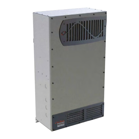
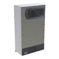
Inverter/Charger
Brand:
Alpha Group
| Category:
Inverter
| Size: 2 MB
Table of Contents
Table of Contents
3
Introduction
5
Audience
5
Welcome to Outback Power Technologies
5
Figure 1 Radian Series Inverter/Charger
5
Components and Accessories
6
Table 1 Components and Accessories
6
Figure 2 Radian Inverter and Components
6
Planning
7
Applications
7
Figure 3 Applications (Example)
7
Input Modes
8
Renewable Energy
8
Battery Bank
9
Table 2 Battery Bank Elements
10
Generator
11
Maintenance Bypass Switching
12
Figure 4 Bypass Switching
12
Figure 5 Bypass Switching for Multiple Inverters
12
Installation
13
Location and Environmental Requirements
13
Dimensions
13
Figure 6 Inverter Dimensions
13
Figure 7 System Dimensions
14
Tools Required
15
Mounting
15
Figure 8 Installing the Mounting Plate
15
Figure 9 Mounting the Inverter
16
Component Mounting
17
Figure 10 Mounting for System Components
17
Removing Front Cover
18
Figure 11 Removing the Front Cover
18
Terminals and Ports
19
Figure 12 DC Terminals, Ribbon Cables, and Auxiliary Terminals
19
Figure 13 AC Terminals, Ports, and Ground Bus
20
Wiring
21
Grounding
21
Table 3 Ground Conductor Size and Torque Requirements
21
Figure 14 Chassis Ground TBB
21
DC Wiring
22
Figure 15 GS7048E and GS3548E Battery Terminals
22
Table 4 DC Conductor Size and Torque Requirements
23
Figure 16 DC Cable Hardware (Radian Inverter)
23
AC Wiring
24
Figure 17 AC Terminals
24
Figure 18 AC Sources
25
Accessory Wiring
26
Figure 19 Accessory Connections
26
Figure 20 ON/OFF Jumper and Connections
26
AUX Wiring
27
Figure 21 AUX Connections for Vent Fan (Example)
27
Generator Control
28
Figure 22 AUX Connections for Diversion (Example)
28
Figure 23 Two-Wire Generator Start (RELAY AUX)
29
Figure 24 Two-Wire Generator Start (12V AUX)
29
Figure 25 Three-Wire Generator Start (Example)
30
AC Configurations
31
Single-Inverter
31
Figure 26 Single-Inverter AC System
31
Figure 27 Single-Inverter AC Wiring with GS Load Center
32
Multiple-Inverter AC Installations (Stacking)
33
Figure 28 Outback Communications Manager and System Display
33
Figure 29 Example of Parallel Stacking Arrangement (Three Inverters)
35
Figure 30 Parallel AC System
36
Figure 31 Parallel AC Wiring with GS Load Centers
37
Figure 32 Example of Three-Phase Stacking (Three Inverters)
38
Figure 33 Example of Three-Phase Stacking (Nine Inverters)
38
Figure 34 Three-Phase AC System
40
Figure 35 Three-Phase AC Wiring with GS Load Centers
41
Functional Test
42
Preventative Maintenance
42
Table 5 AS4777.3 Acceptance Settings
42
Symbols, Terms, and Definitions
43
Symbols Used
43
Definitions
43
Table 6 Terms and Definitions
44
Index
45
Advertisement
Advertisement
Related Products
Alpha Group OutBack Power GS8048A
Alpha Group OutBack Power GS7048E
Alpha Group OutBack Power Radian Series
Alpha Group OutBack Power FLEXware Integrated Combiner Solution Plus
Alpha Group OutBack Power FLEXmax Extreme Series
Alpha Group OutBack Power FM Extreme-150VDC
Alpha Group OutBack Power Mate Micro
Alpha Group OutBack Power MATE3
Alpha Group OutBack Power EnergyCell PLC Series
Alpha Group OutBack Power EnergyCell 200PLC
Alpha Group Categories
Controller
Inverter
Control Unit
Camera Accessories
Motorized Toy Car
More Alpha Group Manuals
Login
Sign In
OR
Sign in with Facebook
Sign in with Google
Upload manual
Upload from disk
Upload from URL