Sign In
Upload
Manuals
Brands
Allied Telesis Manuals
Switch
x320-11GPT
Allied Telesis x320-11GPT Manuals
Manuals and User Guides for Allied Telesis x320-11GPT. We have
1
Allied Telesis x320-11GPT manual available for free PDF download: Installation Manual
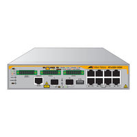
Allied Telesis x320-11GPT Installation Manual (158 pages)
Gigabit Layer 3+ Ethernet Switches with External Power Supply Unit(s)
Brand:
Allied Telesis
| Category:
Switch
| Size: 8 MB
Table of Contents
Electrical Safety and Emissions Standards
3
US Federal Communications Commission
3
Industry Canada
3
Regulatory Approvals
4
Translated Safety Statements
5
Table of Contents
7
Preface
15
Safety Symbols Used in this Document
16
Contacting Allied Telesis
17
Chapter 1: Overview of the X320-10GH Switch
20
Front Panel
20
Figure 1: Front Panel of the X320-10GH Switch
20
Features
21
Ports 1 to 8
21
Poe+ Budgets
21
Ports 9 and 10
21
Additional Features
21
Table 1: Maximum Poe Ports Supported on the X320-10GH Switch
21
Installation Options
22
Management Methods
22
USB Port
22
Ports 1 to 8
23
Specifications
23
Table 2: Specifications for Ports 1 to 8 on the X320-10GH Switch
23
Powered Device Classes
24
Ports 1 to 8 Leds
24
Figure 2: Leds for Ports 1 to 8 on the X320-10GH Switch
24
Table 3: Supported Powered Device Classes on Ports 1 to 8 of the X320-10GH Switch
24
Table 4: Leds for Ports 1 to 8 on the X320-10GH Switch
25
Cable Requirements
26
PWR300 Power Supply
27
Power Supply Unit LED
27
Figure 3: PWR300 Power Supply
27
Table 5: Fault and Power LEDS
27
Poe Port Priorities
28
Table 6: Denial of Ports by Priority
29
SFP Transceiver Ports
31
SFP Transceivers
31
Leds
31
Figure 4: SFP Transceiver Ports Leds
31
Table 7: LEDS for the SFP Transceiver Ports
31
USB Port
32
USB Port LED
32
Figure 5: X320-10GH USB Port and LED
32
Table 8: USB LED
32
Console Port
33
Fault and Power Leds
34
Switch Leds
34
Figure 6: Fault and Power Leds
34
Table 9: Fault and Power LEDS
34
Eco-Friendly Command
35
Planning the Installation
36
Table 10: Port 1 to 8 Worksheet for the X320-10GH Switch
36
Table 11: Worksheet Column Descriptions
37
Table 12: Power Worksheet for the X320-10GH Switch
38
Chapter 2: Overview of the X320-11GPT Switch
40
Front Panel
40
Figure 7: Front Panel of the X320-11GPT Switch
40
Features
41
Ports 1 to 8
41
Port 11
41
Poe+ Budgets
41
Ports 9 and 10
41
Additional Features
41
Installation Options
42
Management Methods
42
USB Port
42
Ports 1 to 8
43
Specifications
43
Table 13: Specifications for Ports 1 to 8 on the X320-11GPT Switch
43
Powered Device Classes
44
Ports 1 to 8 Leds
44
Figure 8: Leds for Ports 1 to 8 on the X320-11GPT Switch
44
Table 14: Supported Powered Device Classes on Ports 1 to 8 of the X320-11GPT Switch
44
Table 15: Leds for Ports 1 to 8 on the X320-11GPT Switch
45
Cable Requirements
46
Port 11 - Poe in Pass-Through
47
Powered Device Classes
47
Poe Budget
47
Table 16: Poe Budget from Port 11 for Ports 1 to 8 on the X320-11GPT Switch
47
Port 11 Leds
48
Figure 9: Leds for Port 11 on the X320-11GPT Switch
48
Table 17: Leds for Port 11 on the X320-11GPT Switch
48
Cable Requirements
49
PWR90ADP AC/DC Power Adapter
50
Figure 10: PWR90ADP AC/DC Power Adapter
50
Poe Port Priorities
51
SFP Transceiver Ports
52
SFP Transceivers
52
Leds
52
Figure 11: SFP Transceiver Ports Leds
52
Table 18: LEDS for the SFP Transceiver Ports
52
USB Port
53
USB Port LED
53
Figure 12: X320-11GPT USB Port and LED
53
Table 19: USB LED
53
Console Port
54
Fault and Power Leds
55
Figure 13: Fault and Power Leds
55
Table 20: Fault and Power LEDS
55
Eco-Friendly Command
56
Switch Markings
57
Planning the Installation
58
Table 21: Port 1 to 8 Worksheet for the X320-11GPT Switch
58
Table 22: Worksheet Column Descriptions
59
Table 23: Power Worksheet for the X320-11GPT Switch
60
Chapter 3: Beginning the Installation
61
Reviewing Safety Precautions
62
Choosing a Site for the Device
67
Unpacking the Equipment
69
X320-10GH Switch
69
Figure 14: X320-10GH or Shipping Box
69
X320-11GPT Switch
70
Figure 15: X320-11GPT Shipping Box
70
PWR300 Power Supply
71
Figure 16: PWR300 Shipping Box
71
Accessory Kits
72
X320-10GH Switch Accessory Kit
72
Figure 17: X320-10GH Switch Accessory Kit
72
X320-11GPT Switch Accessory Kit
73
Figure 18: X320-11GPT Switch Accessory Kit
73
19-Inch Rack Mount Kit
74
Figure 19: Rack Mount Kit
74
PWR300 Power Supply Accessory Kit
75
Figure 20: PWR300 Power Supply Accessory Kit
75
RKMT-J24 Wall Mount Kit
76
Figure 21: RKMT-J24 Wall Mount Kit
76
DRMT-J03 DIN Rail Mount Kit
77
RKMT-J15 Tray Bracket Mount Kit
77
Figure 22: DRMT-J03 DIN Rail Mount Kit
77
Figure 23: RKMT-J15 Tray Bracket Mount Kit
77
Chapter 4: Installing the Device on a Table or Desktop
79
Planning the Installation
80
Figure 24: Required Minimum Distances between Devices for a Desk or Table Installation
80
Installing the Switch on a Table or Desktop
81
Figure 25: Affixing the Adhesive Feet
81
Chapter 5: Installing the Device in an Equipment Rack
83
Overview of Installing the Device in an Equipment Rack
84
Figure 26: Rack Mount Kit Brackets and Device
84
Figure 27: X320-10GH Switch and PWR300 Power Supplies in the RKMT-J15 Bracket
85
Installing the Device in an Equipment Rack with the Rack Mount Kit Brackets
86
Required Items for the Rack Mount Kit Brackets
86
Device Orientations in the Equipment Rack
86
Figure 28: Bracket Holes
87
Installing the Device with the Brackets
88
Figure 29: Device Orientation with the Front Panel Facing the Front of the Equipment Rack
88
Figure 30: Attaching the Brackets to the Device
89
Figure 31: Attaching the Bracket Extension to the Device
89
Figure 32: Installing the Device in an Equipment Rack
90
Figure 33: Device Secured in an Equipment Rack
91
Installing the Device in an Equipment Rack with the RKMT-J15 Bracket
92
Required Items for the RKMT-J15 Bracket
92
Installing the Device with the RKMT-J15 Bracket
92
Figure 34: Installing the RKMT-J15 Bracket in the Equipment Rack
93
Figure 35: Loosening the Two Thumbscrews on the Front of the RKMT-J15 Bracket
93
Figure 36: Sliding out the Tray of the RKMT-J15
94
Figure 37: Placing a Device in the RKMT-J15 Bracket
94
Figure 38: Securing the Device to the RKMT-J15 Bracket
95
Figure 39: Sliding in the Bracket Tray
95
Figure 40: Tightening the Two Thumbscrews on the RKMT-J15 Bracket
96
Chapter 6: Installing the Device on the DRMT-J03 DIN Rail
97
Installing the Device on the DRMT-J03 DIN Chassis Bracket
98
Figure 41: DRMT-J03 DIN Chassis Bracket
98
Figure 42: Placing the Device on the DRMT-J03 DIN Chassis Bracket
98
Figure 43: Screwing the Device to the DRMT-J03 DIN Chassis Bracket
99
Installing the Device on a DIN Rail
100
Figure 44: Orientation of the Device on a DIN Rail
100
Figure 45: Pressing down on the Spring-Loaded Lever
100
Figure 46: Installing the Device on a DIN Rail
101
Figure 47: Verifying the DIN Rail Installation
102
Chapter 7: Installing the Device on a Wall
103
Device Orientations on a Wall
104
Figure 48: Positioning the X320-10GH Switch or X320-11GPT Switch on the Wall
104
Figure 49: Positioning the PWR300 Power Supply on the Wall
104
Installation Guidelines
105
Tools and Material
105
Plywood Base for a Wall with Wooden Studs
107
Figure 50: Device on the Wall with a Plywood Base
107
Figure 51: Steps to Installing the Device with a Plywood Base
108
Installing a Plywood Base
109
Installing the Device on a Plywood Base
110
Figure 52: Installing the Wall Brackets on a Switch
111
Figure 53: Installing the Wall Brackets on a Power Supply
111
Figure 54: Securing the Device to the Plywood Base
112
Installing the Device on a Concrete Wall
113
Figure 55: Marking the Locations of the Bracket Holes on a Concrete Wall
114
Figure 56: Installing the Device on a Concrete Wall
115
Chapter 8: Cabling the Networking Ports
117
Cabling Twisted Pair Ports
118
Guidelines to Handling SFP Transceivers
119
Installing SFP Transceivers
120
Figure 57: SFP Ports 9 and 10
120
Figure 58: Installing an SFP Transceiver
121
Figure 59: SFP Transceiver Clicking into Place
121
Figure 60: Positioning the SFP Handle in the Upright Position
122
Figure 61: Connecting a Fiber Optic Cable to an SFP Transceiver
122
Chapter 9: Powering on the Switch
123
Powering on the X320-10GH Switch
124
Connecting the PWR300 Power Supply
124
Figure 62: Connecting the External Harness to the X320-10GH Switch
124
Powering on the PWR300 Power Supply
125
Figure 63: Connecting the PWR300 Power Supply to the X320-10GH Switch
125
Figure 64: Installing the Power Cord Retaining Clip on the PWR300 Power Supply
126
Figure 65: Connecting the AC Power Cord
126
Figure 66: Lowering the Power Cord Retaining Clip
127
Figure 67: Connecting the Power Cord to an AC Power Source
127
Powering on the X320-11GPT Switch
128
Connecting Port 11 to a Poe Power Source
128
Connecting the PWR90ADP Power Adapter
129
Figure 68: Connecting the PWR90ADP Power Adapter to the X320-11GPT Switch
129
Figure 69: Connecting the Power Cord to the Power Adapter
129
Powering on the PWR90ADP AC/DC Adapter
130
Figure 70: Connecting the Power Cord to the Power Adapter
131
Figure 71: Connecting the Power Cord to an AC Power Source
131
Monitoring the Initialization Processes
132
Starting a Local Management Session
133
Verifying the Poe Budget
135
X320-10GH
135
X320-11GPT
135
Chapter 10: Troubleshooting
137
X320-10GH Switch
138
PWR300 Power Supply
138
Poe++ on Ports 1 to 8
141
X320-11GPT Switch
142
Port 11 Poe-IN
142
PWR90ADP AC/DC Adapter
142
Poe+ on Ports 1 to 8
142
Twisted Pair Ports 1 to 8
144
SFP Ports
145
Appendix A: Technical Specifications
147
Physical Specifications
148
Figure 72: PWR300 Dimensions
148
Table 24: Product Dimensions
148
Figure 73: X320-10GH Dimensions
149
Figure 74: X320-11GPT Dimensions
149
Table 25: Product Weights
150
Table 26: Ventilation Requirements
150
Environmental Specifications
151
Table 27: Environmental Specifications
151
Table 28: Operating Temperature Derating
151
Power Specifications
153
Table 29: Maximum Power Consumptions
153
Table 30: Input Voltages
153
Table 31: Heat Dissipation
153
Certifications
154
Table 32: Product Certifications
154
Twisted Pair Port Pinouts
155
Figure 75: RJ-45 Socket Pin Layout (Front View)
155
Table 33: Pin Signals for 10 and 100 Mbps
155
Table 34: Pin Signals for 1Gbps
156
Style Serial Console Port Pinouts
157
Table 35: RJ-45 Style Serial Console Port Pin Signals
157
Table 36: X320-10GH DC-IN Pin Signals
157
Advertisement
Advertisement
Related Products
Allied Telesis x320 Series
Allied Telesis x320-10GH
Allied Telesis x3100 Series
Allied Telesis SwitchBlade x3106
Allied Telesis x310-26FT
Allied Telesis x310-26FP
Allied Telesis x310-50FP
Allied Telesis x310-50FT
Allied Telesis x330-10GTX
Allied Telesis x330 Series
Allied Telesis Categories
Switch
Network Router
Media Converter
Network Hardware
Wireless Access Point
More Allied Telesis Manuals
Login
Sign In
OR
Sign in with Facebook
Sign in with Google
Upload manual
Upload from disk
Upload from URL