Sign In
Upload
Manuals
Brands
Allied Telesis Manuals
Power Supply
AT-RPS3000
Allied Telesis AT-RPS3000 Manuals
Manuals and User Guides for Allied Telesis AT-RPS3000. We have
1
Allied Telesis AT-RPS3000 manual available for free PDF download: Installation Manual
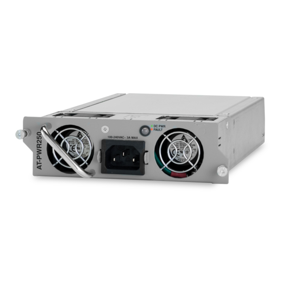
Allied Telesis AT-RPS3000 Installation Manual (92 pages)
Redundant Power Supply
Brand:
Allied Telesis
| Category:
Power Supply
| Size: 5.2 MB
Table of Contents
Installation Guide
1
Table of Contents
5
Preface
11
Document Conventions
12
Where to Find Web-Based Guides
13
Contacting Allied Telesis
14
Online Support
14
Email and Telephone Support
14
Warranty
14
Returning Products
14
Sales or Corporate Information
14
Management Software Updates
14
Chapter 1: Overview
15
Features
16
LED Panel
16
Figure 1: LED Panel
16
Power Supply Slots
17
RPS Connectors
17
Figure 2: Slots a and B for the Power Supply Modules
17
Figure 3: Slot a and RPS 1 and 2 Ports
17
Figure 4: Slot B and RPS 3 and 4 Ports
18
Figure 5: RPS Ports
18
Power Supply Modules
19
Table 1: Power Supply Modules
19
Table 2: Valid and Invalid Power Supply Combinations in the AT-RPS3000 Chassis
20
System Power and Power for Poe
21
System Power
21
Poe+ Power
22
Figure 6: Removable and Non-Removable Power Supply Modules in X610 Switches
22
Low-Power and High-Power Switches
24
Table 3: Low-Power and High-Power Switches
24
Table 4: Valid and Invalid Configurations of Low- and High-Power Switches for a Power Supply Module
24
Configuration Examples
25
Low-Power Switches
25
Figure 7: Example of a Single Low-Power Switch Connected to an RPS System Port
25
Figure 8: Example of a Non-Poe+, Low-Power Switch Connected to an RPS Poe+/System Port
26
Figure 9: Example of Two Low-Power Switches
26
Figure 10: Example of Four Low-Power Switches
27
High-Power Switches
28
Figure 11: Example of Low-Power and High-Power Switches
28
Figure 12: Example of Two High-Power Switches on the System Ports
29
Figure 13: Example of Two High-Power, Non-Poe+ Switches on the Poe+/System Ports
29
Poe+ Switches
30
Figure 14: Example of One Poe+ Switch
30
Figure 15: Example of Two Poe+ Switches
31
Figure 16: Example of Low-Power Poe+ and Non-Poe+ Switches
32
Invalid Configurations
33
Figure 17: Example of Low-Power Poe+ and Non-Poe+ Switches
33
Figure 18: Example of an Invalid Configuration - a
34
Figure 19: Example of an Invalid Configuration - B
35
Choosing a Power Supply Module
36
Non-Poe+ Switches
36
Figure 20: Example of Power Modules and Non-Poe+ Switches
36
Poe+ Switches
37
Figure 21: Two AT-PWR800 Modules Providing up to 480 Watts, with Full Redundancy
37
Figure 22: Two AT-PWR800 Modules for 480 to 960 Watts, with Limited Redundancy
38
Figure 23: Two AT-PWR1200 Modules Providing up to 780 Watts, with Full Redundancy
38
Figure 24: Two AT-PWR1200 Modules for 780 to 1560 Watts, with Limited Redundancy
39
Power Module Combinations for Poe+ Switches
40
Figure 25: Example of X610 Series Switches and AT-RPS3000 Chassis with Different Power Supply Modules
40
Table 5: Power Supply Module Combinations for Poe+ Switches
40
Leds
42
Module A/B Ports Leds
42
Figure 26: LED Panel
42
Figure 27: Module a Ports Leds
42
Figure 28: Module B Ports Leds
43
Table 6: Module a and B Ports Leds
43
Power Module Status Leds
44
Figure 29: Power Module Status Leds
44
Table 7: Power Module Status Leds
45
Power Module LED
46
Figure 30: Power Module LED
46
Table 8: Power Module LED
46
On/Off Power Switches
47
Figure 31: RPS Port On/Off Switches
47
Guidelines
48
Chapter 2: Installing the AT-RPS3000 Chassis and Power Supply Modules
49
Reviewing Safety Precautions
50
Planning the Installation
52
Figure 32: 100 - 125 VAC 125 V NMA 5-20 Plug and Receptacle
52
Unpacking the AT-RPS3000 Chassis and Power Supply Modules
54
AT-RPS3000 Chassis
54
Table 9: AT-RPS3000 Chassis Components
54
Power Supply Modules
55
Table 10: Power Supply Module Components
55
Selecting a Location for the AT-RPS3000 Chassis in the Equipment Rack
57
Figure 33: Positioning the AT-RPS3000 Chassis in the Equipment Rack
57
Figure 34: Unauthorized AT-RPS3000 Chassis and X610 Series Switch Installations
57
Installing the AT-RPS3000 Chassis in an Equipment Rack
58
Figure 35: Turning the Switch Upside down
58
Figure 36: Removing the Plastic Feet
58
Figure 37: Attaching the Equipment Rack Brackets
59
Figure 38: Mounting the AT-RPS3000 Redundant Power Supply in an Equipment Rack
59
Installing a Power Supply Module
61
Figure 39: Removing the Blank Shipping Panel from the Back Panel
61
Figure 40: Installing a Power Supply Module
62
Figure 41: Securing a Power Supply Module
63
Figure 42: Installing a Power Cord Retaining Clip
63
Figure 43: Installing the Slot Cover
64
Figure 44: Securing the Slot Cover
64
Connecting the AT-RPS3000 Chassis to the X610 Series Switch
65
Figure 45: Connecting the AT-RPS-CBL1.0 Cable to the X610 Series Switch
65
Figure 46: Securing the AT-RPS-CBL1.0 Cable to the Switch
66
Figure 47: RPS Port On/Off Buttons and CABLE Leds
66
Figure 48: Connecting the AT-RPS-CBL1.0 Cable to the AT-RPS3000 Chassis
67
Figure 49: Securing the AT-RPS-CBL1.0 Cable to the AT-RPS3000 Chassis
68
Powering on the Power Supply Modules
69
Figure 50: Raising the Power Cord Retaining Clip
69
Figure 51: Connecting the AC Power Cord
70
Figure 52: Lowering the Power Cord Retaining Clip
70
Figure 53: Lowering the Power Cord Retaining Clip
71
Figure 54: Checking the FAN and DC out Leds in the LED Panel
72
Figure 55: Checking the LOAD and CABLE Leds in the LED Panel
73
Chapter 3: Removing Power Supply Modules
75
Removing the AT-RPS-CBL1.0 Cable
76
Figure 56: Loosening the Thumbscrews that Secure the AT-RPS-CBL1.0 Cable to the AT-RPS3000 Chassis
76
Figure 57: Removing the AT-RPS-CBL1.0 Cable from the AT-RPS3000 Chassis
77
Removing an AC Power Supply Module
78
Figure 58: Raising the Power Cord Retaining Clip
78
Figure 59: Removing the Power Cord
79
Figure 60: Loosening the Two Captive Screws
80
Figure 61: Removing the Power Supply from the Chassis
80
Figure 62: Installing the Slot Cover
81
Figure 63: Securing the Slot Cover
81
Chapter 4: Troubleshooting
83
Appendix A: Technical Specifications
87
Physical Specifications
87
Environmental Specifications
87
Power Specifications
88
Certifications
88
Port Pin-Outs
89
Figure 64: Port Pin-Outs for the RSP System and Poe+/System Ports
89
Table 11: RPS 1 and 3 System Ports
89
Table 12: RPS 2 and 4 Poe+/System Ports
90
Pin Description
91
Advertisement
Advertisement
Related Products
Allied Telesis AT-RPS8000
Allied Telesis AT-FAN01
Allied Telesis AT-FAN03
Allied Telesis AT-PWR05
Allied Telesis AT-9408LC/SP Series
Allied Telesis AT-PWR01
Allied Telesis AT-PWR250
Allied Telesis AT-PWR800
Allied Telesis AT-PWR1200
Allied Telesis AT-FAN01AT-FAN03
Allied Telesis Categories
Switch
Network Router
Media Converter
Network Hardware
Wireless Access Point
More Allied Telesis Manuals
Login
Sign In
OR
Sign in with Facebook
Sign in with Google
Upload manual
Upload from disk
Upload from URL