Sign In
Upload
Manuals
Brands
Allen-Bradley Manuals
I/O Systems
Compact 1769-IR6
Allen-Bradley Compact 1769-IR6 Manuals
Manuals and User Guides for Allen-Bradley Compact 1769-IR6. We have
1
Allen-Bradley Compact 1769-IR6 manual available for free PDF download: User Manual
Allen-Bradley Compact 1769-IR6 User Manual (116 pages)
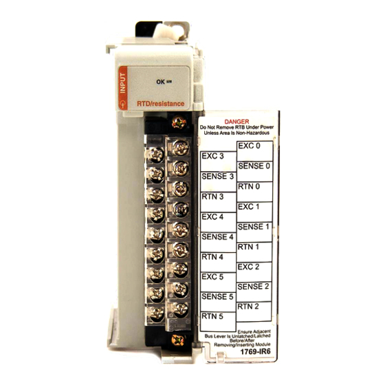
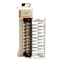
I/O RTD/resistance Input Module
Brand:
Allen-Bradley
| Category:
I/O Systems
| Size: 2 MB
Table of Contents
Table of Contents
3
How to Use this Manual
7
Manual Contents
7
Related Documentation
8
Preface
7
Who Should Use this Manual
7
Conventions Used in this Manual
8
Rockwell Automation Support
9
Local Product Support
9
Technical Product Assistance
9
Your Questions or Comments on the Manual
9
Chapter 1 General Description
11
Overview
11
RTD Compatibility
12
Resistance Device Compatibility
15
Hardware Features
16
General Diagnostic Features
17
System Overview
17
System Operation
17
Module Operation
18
Module Field Calibration
18
Before You Begin
19
Chapter 2
19
Quick Start for Experienced Users
19
Required Tools and Equipment
19
What You Need to Do
19
Chapter 3 Compliance to European Union Directives
25
EMC Directive
25
Low Voltage Directive
25
Installation and Wiring
25
General Considerations
26
Hazardous Location Considerations
26
Prevent Electrostatic Discharge
27
Remove Power
27
Selecting a Location
27
Power Requirements
26
System Assembly
28
Mounting
30
Minimum Spacing
30
Panel Mounting
30
DIN Rail Mounting
31
Replacing a Single Module Within a System
31
Field Wiring Connections
32
System Wiring Guidelines
32
RTD Wiring Considerations
33
Terminal Door Label
34
Removing and Replacing the Terminal Block
34
Wiring the Finger-Safe Terminal Block
35
Wiring the Modules
36
Wiring Rtds
37
Wiring Resistance Devices (Potentiometers)
38
Module Data, Status, and Channel Configuration
41
Accessing Input Image File Data
42
Input Data File
42
Input Data Values
43
General Status Flag Bits (S0 to S5)
43
Open-Circuit Flag Bits (OC0 to OC5)
44
Over-Range Flag Bits (O0 to O5)
44
Under-Range Flag Bits (U0 to U5)
44
Configuring Channels
45
Configuration Data File
45
Channel Configuration
46
Enabling or Disabling a Channel (Bit 15)
48
Selecting Data Format (Bits 12 to 14)
48
Selecting Input/Sensor Type (Bits 8 to 11)
53
Selecting Temperature Units/Mode (Bit 7)
54
Selecting Open-Circuit Response (Bits 5 and 6)
54
Selecting Cyclic Lead Compensation (Bit 4)
54
Selecting Excitation Current (Bit 3)
55
Setting Filter Frequency (Bits 0 to 2)
55
Selecting Enable/Disable Cyclic Autocalibration (Word 6, Bit 0)
59
Determining Effective Resolution and Range
59
Determining Module Update Time
66
Effects of Autocalibration on Module Update Time
67
Enabled
68
Effects of Cyclic Lead Wire Compensation on Module Update Time
70
Calculating Module Update Time with Cyclic Lead Wire Compensation Enabled
71
Impact of Autocalibration and Lead Wire Compensation on Module Startup
72
Effects of Autocalibration on Accuracy
73
Chapter 4 Module Memory Map
41
Input Image
42
Configuration File
42
Chapter 5 Safety Considerations
75
Indicator Lights
75
Activating Devices When Troubleshooting
75
Stand Clear of the Equipment
76
Program Alteration
76
Safety Circuits
76
Diagnostics and Troubleshooting
75
Module Operation Vs. Channel Operation
76
Channel Diagnostics
77
Invalid Channel Configuration Detection
77
Out-Of-Range Detection
77
Open-Wire or Short-Circuit Detection
78
Power-Up Diagnostics
77
Module Error Definition Table
78
Module Error Field
79
Extended Error Information Field
79
Non-Critical Vs. Critical Module Errors
78
Error Codes
80
Contacting Rockwell Automation
82
Module Inhibit Function
82
Appendix A
83
General Specifications
83
Specifications
83
Input Specifications
84
Cable Specifications
86
RTD Standards
86
Appendix B Module Addressing
87
1769-IR6 Configuration File
88
Module Addressing and Programming with Micrologix 1500 and Rslogix
87
Configuring the 1769-IR6 in a Micrologix 1500 System
88
Configuring the 1769-IR6 RTD
93
Appendix C
96
Configuring I/O Modules
96
Configuring a 1769-IR6 RTD Input Module
97
Positive Decimal Values
105
Negative Decimal Values
106
Advertisement
Advertisement
Related Products
Allen-Bradley 1769-IQ32
Allen-Bradley 1769-ECL
Allen-Bradley 1769-ECR
Allen-Bradley 1769-ECRK
Allen-Bradley Compact 1769-IF4
Allen-Bradley 1769-HSC
Allen-Bradley 1769-IT6
Allen-Bradley 1762-IR4
Allen-Bradley 1762-IQ8OW6
Allen-Bradley MicroLogix 1762-IQ32T
Allen-Bradley Categories
Control Unit
Controller
I/O Systems
Power Supply
Switch
More Allen-Bradley Manuals
Login
Sign In
OR
Sign in with Facebook
Sign in with Google
Upload manual
Upload from disk
Upload from URL