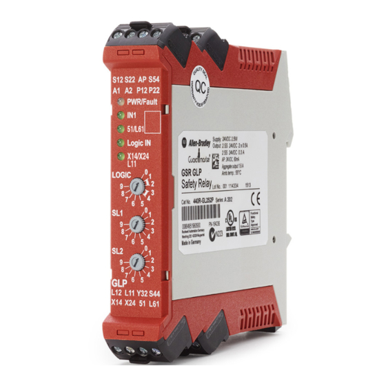
Sign In
Upload
Manuals
Brands
Allen-Bradley Manuals
Other
440R-GL2S2P
Allen-Bradley 440R-GL2S2P Safety Relay Manuals
Manuals and User Guides for Allen-Bradley 440R-GL2S2P Safety Relay. We have
1
Allen-Bradley 440R-GL2S2P Safety Relay manual available for free PDF download: User Manual
Allen-Bradley 440R-GL2S2P User Manual (66 pages)
Guard-Locking Proximity Inputs Safety Relay
Brand:
Allen-Bradley
| Category:
Other
| Size: 7.54 MB
Table of Contents
Table of Contents
3
Firmware Revision History
7
Preface
7
Purpose of this Manual
7
Summary of Changes
7
Who Should Use this Manual
7
Additional Resources
8
Terminology
8
Chapter 1 Hardware Features
9
Overview
9
Logic Functions
10
Logic Setting 1 - Cat 1 Stop, Logic in off
10
Logic Setting 2 - Cat 1 Stop with Logic in
10
Logic Setting 3 - Safe Limited Slow Speed, Logic in off
11
Logic Setting 4 - Safe Limited Slow Speed with Logic in
11
Logic Setting 5
12
Unlock and Automatic Reset
12
Logic Setting 8 - Speed Status Only
12
Chapter 2 Mounting Dimensions
13
DIN Rail Mounting and Removal
13
Removal
14
Spacing
14
Installation
13
Enclosure Considerations
14
Removable Terminals
14
Preventing Excessive Heat
15
Chapter 3 Wiring Requirements and Recommendation
17
Wire Size
17
Terminal Torque
17
Terminal Assignments
18
Power, Ground, and Wire
17
Connecting a Power Supply
19
Grounding the Controller
19
Guard Locking Connections
20
Devices with Mechanical Contacts
20
Safety Devices with OSSD Outputs
21
Proximity Sensor Connections
20
Unlock Request Input
21
Lock and Reset Request Input
22
Lock and Unlock Signals
22
Lock Outputs
23
TLS3-GD2 Connections
23
TLS-Z, 440G-LZ, and MAB Connections
23
Multiple Guard Locking Devices and Power to Lock
24
No Guard Locking
25
Safety Outputs
25
Single Wire Safety (SWS)
26
Chapter 4 Logic Switch Settings
27
SLS1 Switch Setting
28
Sls2/Time Switch Setting
28
Configuration Process
29
Chapter 5
31
Status Indicators During Normal Operation
31
Status Indicators During Power-Up
31
Status Indicators During Diagnostics
32
Introduction to Pulse Testing
33
Chapter 6
34
Pulse Testing for Inputs
34
Test of OSSD Outputs
34
Webpage
35
Chapter 7 Logix AOP
36
Chapter 8 Proximity Sensor Targets
39
Proximity Sensor Selection
39
Chapter 9
43
Example Schematic
43
Sequence Diagram
44
Sequence Steps
44
Stop Cat 1 Example
43
SLS Example
46
Example Schematic
46
Sequence Diagram
47
Sequence Steps
47
Rockwell Automation Publication 440R-UM012E-EN-P - November
48
Delayed Unlock with Auto Reset Example
49
Example Schematic
49
Sequence Diagram
50
Sequence Steps
50
Status Only Example
51
Example Schematic
51
Sequence Diagram
52
Sequence Steps
52
Appendix A General Specifications
53
Environmental Specifications
53
Specifications
53
Input IN1
54
Proximity Sensor Signals
54
Lock Unlock Request
55
Lock Unlock Signals
55
Auxiliary Signal
56
Single Wire Safety Input Signal
56
Safety/Pulse Test Outputs
57
Single Wire Safety Output Signal
57
Response Times
58
Appendix B Agency Certifications
59
Compliance to European Union Directives
59
Machine Safety Directive
59
SIL Rating
60
Performance Level/Category
60
EMC Directive
60
Regulatory Approvals
59
Index
61
Advertisement
Advertisement
Related Products
Allen-Bradley Guardmaster EtherNet/IP 440R-ENETR
Allen-Bradley SensaGuard 440N-Z21S16B
Allen-Bradley SensaGuard 440N-Z21S17H
Allen-Bradley SensaGuard 440N-Z21S17B
Allen-Bradley SensaGuard 440N-Z21S16H
Allen-Bradley SensaGuard 440N-Z21S26J
Allen-Bradley SensaGuard 440N-Z21X16H
Allen-Bradley SensaGuard 440N-Z21U16H
Allen-Bradley SensaGuard 440N-Z21U26J
Allen-Bradley GuardShield 440L-P2K series
Allen-Bradley Categories
Control Unit
Controller
I/O Systems
Power Supply
Switch
More Allen-Bradley Manuals
Login
Sign In
OR
Sign in with Facebook
Sign in with Google
Upload manual
Upload from disk
Upload from URL