
Summary of Contents for Allen-Bradley 440R-GL2S2P
- Page 1 User Manual Original Instructions Guard-Locking Proximity Inputs Safety Relay Catalog Number 440R-GL2S2P...
- Page 2 Important User Information Read this document and the documents listed in the additional resources section about installation, configuration, and operation of this equipment before you install, configure, operate, or maintain this product. Users are required to familiarize themselves with installation and wiring instructions in addition to requirements of all applicable codes, laws, and standards.
-
Page 3: Table Of Contents
Table of Contents Preface Who Should Use This Manual? ....... . . 7 Purpose of This Manual . - Page 4 Table of Contents Lock Outputs ..........23 TLS3-GD2 Connections.
- Page 5 Table of Contents Delayed Unlock with Auto Reset Example ..... . 49 Example Schematic ........49 Sequence Diagram .
- Page 6 Table of Contents Notes: Rockwell Automation Publication 440R-UM012E-EN-P - November 2018...
-
Page 7: Preface
Preface Who Should Use This Use this manual if you are responsible for designing, installing, programming, or troubleshooting control systems that use the guard locking with proximity Manual? (GLP) safety controller. You must have a basic understanding of electrical circuitry and familiarity with safety-related control systems. -
Page 8: Terminology
A glossary of industrial automation terms and abbreviations. You can view or download publications at http://www.rockwellautomation.com/literature/. To order paper copies of technical documentation, contact your local Allen-Bradley distributor or Rockwell Automation sales representative. Rockwell Automation Publication 440R-UM012E-EN-P - November 2018... -
Page 9: Overview
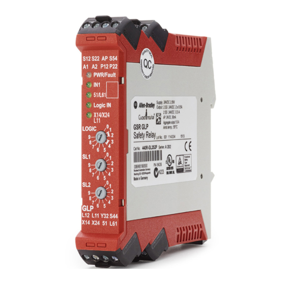
Chapter Overview Hardware Features The Guard Locking Proximity (GLP) inputs special-purpose safety relay is designed to use proximity sensors to detect the safe speed of a machine. The GLP safety relay issues lock or unlock commands to a guard locking interlock based on the speed of the signals that are received from the proximity sensors. -
Page 10: Logic Functions
Chapter 1 Overview The optical communication bus is on the sides of the housing. The GLP safety relay operates with the catalog number 440R-ENETR EtherNet/IP™ network interface to transmit its status to the machine control system over an EtherNet/IP network. The GLP safety relay can be operated with other safety relays in the GSR family by use of the single wire safety (SWS) connection. -
Page 11: Logic Setting 3 - Safe Limited Slow Speed, Logic In Off
Overview Chapter 1 outputs and powers the guard locking interlock through 51 and L61 to unlock the gate. TIP If the SWS input turns back ON or if the Reset button is pressed within the Frequency Measuring Time, the GLP safety relay turns the Y32 auxiliary output back ON. -
Page 12: Logic Setting 5
Chapter 1 Overview Logic Setting 5…8 - Guard Locking with Delayed Unlock and Automatic Reset The GLP safety relay uses two timers to delay the turning ON of the safety outputs and unlocking the gate. When the proximity sensor speed falls below SLS1, the GLP safety relay starts the Frequency Measurement timer. -
Page 13: Installation
Chapter Installation This chapter explains the mounting and terminal removal procedures. It also provides information to select the proper enclosure and help prevent overheating. Mounting Dimensions Figure 2 - Dimensions [mm (in.)] 22.5 (0.88) 113.6 (4.47) 119.14 (4.69) DIN Rail Mounting and The GLP safety relay mounts onto 35 mm DIN rail: 35 x 7.5 x 1 mm (EN 50022 - 35 x 7.5). -
Page 14: Removal
Chapter 2 Installation Removal To remove the GLP safety relay, use a screwdriver to pry the DIN rail latch downwards until it is in the unlatched position. Then, swing the module up. Spacing The GLP safety relay can be mounted directly next to other GSR safety relays. When the catalog number 440R-ENETR EtherNet/IP network interface is used, the GSR must be mounted within 10 mm (0.4 in.) of adjacent modules to maintain effective communication. -
Page 15: Preventing Excessive Heat
Installation Chapter 2 This equipment is supplied as open-type equipment. It must be mounted within an enclosure that is suitably designed for those specific environmental conditions that are present and appropriately designed to help prevent personal injury as a result of accessibility to live parts. The enclosure must have suitable flame-retardant properties to help prevent or minimize the spread of flame, complying with a flame spread rating of 5VA, V2, V1, V0 (or equivalent) if non-metallic. - Page 16 Chapter 2 Installation Notes: Rockwell Automation Publication 440R-UM012E-EN-P - November 2018...
-
Page 17: Power, Ground, And Wire
Chapter Power, Ground, and Wire Wiring Requirements and ATTENTION: Before you install and wire any device, disconnect power to the Recommendation system. ATTENTION: Calculate the maximum possible current in each power and common wire. Observe all electrical codes that dictate the maximum current allowable for each wire size. -
Page 18: Terminal Assignments
Chapter 3 Power, Ground, and Wire Terminal Assignments Some terminals are designed to have one specific function. Some terminals can perform multiple functions; these terminals must be configured during a power-up routine. Figure 5 - Terminal Identification S12 S22 AP S54 A1 A2 P12 P22 PWR/Fault 51/L61... -
Page 19: Grounding The Controller
Power, Ground, and Wire Chapter 3 Grounding the Controller There are no special grounding requirements. Terminal A2 must be connected to the common of a 24V supply. Connecting a Power Supply An external 24V DC power supply source must provide power for the GLP safety relay. -
Page 20: Proximity Sensor Connections
Chapter 3 Power, Ground, and Wire Proximity Sensor Figure 7 - PNP Proximity Sensor Connections +24V DC Connections Power Monitoring Proximity Sensors 24V Com Figure 8 shows how to connect an NPN (sinking) proximity sensor. You must provide an NPN to PNP converter. The converter should get power from AP and have the same ground reference as the GLP safety relay. -
Page 21: Safety Devices With Ossd Outputs
Power, Ground, and Wire Chapter 3 Because the TLS3-GD2 guard locking switch has multiple contacts in series, the maximum safety performance rating is Cat 3 PLd and SIL 2. TIP Pulse test output X14 can be connected to either S12 or S22. Pulse test output X24 can be connected to either S12 or S22. -
Page 22: Lock And Reset Request Input
Chapter 3 Power, Ground, and Wire Lock and Reset Request The Lock and Reset Input can be connected to the 24V supply through a momentary, normally open push button switch or to a 24V sourcing output of Input a PLC, where the PLC turns the request ON or OFF. Some examples of Rockwell Automation PLC output modules are shown in Figure In some safety system applications, the reset signal also serves as a monitoring... -
Page 23: Lock Outputs
Power, Ground, and Wire Chapter 3 Lock Outputs Terminals 51 and L61 perform the solenoid lock command. There are various connection possibilities, and the GLP safety relay detects the type of connection during configuration. TLS3-GD2 Connections Figure 14 shows a connection from a GLP safety relay to one TLS3-GD2 guard locking switch. -
Page 24: Multiple Guard Locking Devices And Power To Lock
Chapter 3 Power, Ground, and Wire Multiple Guard Locking Devices and Power to Lock When multiple guard locking devices must be connected to one GLP safety relay, an interposing relay or interposing relays may be required; the connection depends on the lock signal/coil characteristics. The solenoids would be driven by the contacts of the interposing relays. -
Page 25: No Guard Locking
Power, Ground, and Wire Chapter 3 No Guard Locking If no guard locking is required for Stop Cat 1 or SLS functions, then 51 and L61 can be left open. The safety inputs S12 and S22 must be connected to 24V DC. -
Page 26: Single Wire Safety (Sws)
Chapter 3 Power, Ground, and Wire Figure 19 shows an example wiring connection of the safety outputs to two contactors. When solenoid type loads are used, use a protective diode to suppress reverse voltage spikes when the contactors turn OFF. Figure 19 - Safety Output Connections +24V DC 24V DC Com... -
Page 27: Logic Switch Settings
Chapter Configuration The GLP safety relay has three multi-position switches on its front panel. These switches set the configuration of the GLP safety relay. Logic Switch Settings The Logic switch determines the operating function of the GLP safety relay and is used to set the configuration. Table 2 - Logic Switch Setting Switch 1 Lock/ Unlock Door Control... -
Page 28: Sls1 Switch Setting
Chapter 4 Configuration SLS1 Switch Setting SLS1 is a 10-position switch that determines the safe limited slow speed, as detected by the proximity sensors, or the Safe Stop Threshold (Speed1). Switch SLS1 applies to all eight logic settings. Table 3 - SLS1 Settings SLS1 Switch Setting Maximum SLOW Speed Frequency Measuring Time... -
Page 29: Configuration Process
Configuration Chapter 4 Table 4 - SLS2/Times Settings SLS2/Time Switch Safe Maximum Speed Configuration Time Configuration 5…8 Setting 1…4 and 8 (Configured from 9) (Configured from 0) No limit 10 Hz 20 Hz 50 Hz 100 Hz 200 Hz 500 Hz 1000 Hz 2000 Hz 3000 Hz... - Page 30 Chapter 4 Configuration 2. Apply power. The PWR/Fault status indicator flashes red continuously. The prior configuration in the EEPROM is erased and the device now prepared for a new configuration. 3. Adjust the Logic, SLS1, and SLS2/Time switches. After 500 ms, the new configuration parameters are acknowledged. Then, after 300 ms, the new parameter is stored in the EEPROM, the power status indicator is solid green.
-
Page 31: Status Indicators During Power-Up
Chapter Diagnostic Status Indicators and Troubleshooting The GLP safety relay has five status indicators to provide operating status and diagnostic information. Status Indicators During During power-up, the status indicators turn ON and OFF during their self- check process. The self-check takes about 5 seconds for Status Only Logic and Power-up 10 seconds for all other Logic Settings. -
Page 32: Status Indicators During Diagnostics
Chapter 5 Diagnostic Status Indicators and Troubleshooting Status Indicators During The flashing of the status indicators indicate diagnostics. The PWR/Fault indicator shows the major fault. The IN1 indicator shows more detail. Diagnostics The flashing rate pauses and then repeats itself. IMPORTANT For accurate diagnostics, always start counting after the first pause. -
Page 33: Introduction To Pulse Testing
Chapter Pulse Testing Functions Introduction to Pulse Testing The test pulses are used by the GLP safety relay to detect three short-circuit conditions: • Between the input terminals and +24V • Between the input terminals and 24V common • Between the two input terminals. The outputs have built in redundancy, as shown in Figure 24. -
Page 34: Pulse Testing For Inputs
Chapter 6 Pulse Testing Functions Pulse Testing for Inputs When configuration starts with Logic Switch setting 9 and goes to a setting from 1 to 4, X14 and X24 terminals generate quick pulses that are used to test for short circuit conditions. This configuration is ideal for guard locking interlocks with mechanical contacts. -
Page 35: Webpage
Chapter Ethernet Communication The GLP safety relay is equipped with optical communication via optical link. With the optical link, diagnostic data can be read from the GLP safety relay and transferred to other devices over an EtherNet/IP network. Figure 28 - Arrangement of EtherNet/IP Network Interface and GSR Relays The catalog number 440R-ENETR EtherNet/IP network interface must be in the left-most position. -
Page 36: Logix Aop
Chapter 7 Ethernet Communication IMPORTANT Using an Ethernet browser to query the 440R-ENETR module is available only with Series A modules. Series B does not have the browsing capability. When you browse the GSR modules, the GLP safety relay appears as Device Type 8. Table 8 shows the GLP safety relay data that can be viewed from the webpage. - Page 37 Ethernet Communication Chapter 7 Figure 31 shows the GLP Logix AOP for the 440R-ENETR Series B. The relay position is now shown as Relayn, where n is the position of the relay with respect to the 440R-ENETR module. Figure 31 - GLP Safety Relay Logix AOP for 440R-ENETR Series B Rockwell Automation Publication 440R-UM012E-EN-P - November 2018...
- Page 38 Chapter 7 Ethernet Communication Notes: Rockwell Automation Publication 440R-UM012E-EN-P - November 2018...
-
Page 39: Proximity Sensor Selection
Chapter Proximity Sensors and Targets Proximity Sensor Selection The GLP safety relay accepts proximity sensors that meet the following requirements: 1. 24V DC powered 2. 3-wire (Power, Ground, and Signal) 3. PNP Output Type 4. Leakage current less than 1 mA. The GLP safety relay does not require the use of safety-rated proximity sensors. - Page 40 Chapter 8 Proximity Sensors and Targets Figure 32 - Proximity Mark (Space Dimensions) >= 3d <= 0.8 Sn Mark Space >= 3 Sn >= 4d >= 2d (1) The spacing distance depends on the type of proximity sensor. Verify the requirements of your proximity sensor. Figure 33 - Target Wheel Example 1 ...
- Page 41 Proximity Sensors and Targets Chapter 8 Figure 36 shows a target wheel that is configured to achieve the maximum resolution. Figure 36 - Maximum Resolution 0.5 Sn 3 Sn Minor Angle The spreadsheet in Figure 37 can be used to calculate the target wheel dimensions to achieve the maximum resolution.
- Page 42 Chapter 8 Proximity Sensors and Targets Notes: Rockwell Automation Publication 440R-UM012E-EN-P - November 2018...
-
Page 43: Stop Cat 1 Example
2 Start Green Grey 4 Gnd Pink S12 S22 33 43 LOGIC SLS1 SLS2/TIME Gate control power supply 440R-GL2S2P 440R-EM4R2 Gate control P12 P22 X14 X24 34 44 circuit Proximity Sensors Gate Unlocked 24V DC Com Rockwell Automation Publication 440R-UM012E-EN-P - November 2018... -
Page 44: Sequence Diagram
Chapter 9 Example Operational Sequence Diagrams Sequence Diagram Figure 39 shows the sequence of operations. This diagram assumes that all components are operating properly and no faults are present. Figure 39 - Operational Sequence for Stop Cat 1 Example Overspeed Max Safe Speed (SLS2) Safely Limited Speed... - Page 45 Example Operational Sequence Diagrams Chapter 9 3. You press the Start button and the motor begins to accelerate and the proximity sensors generate pulses. At some point, the speed becomes faster than the safely limited speed set by SLS1 on the GLP safety relay but stays below the maximum safe speed.
-
Page 46: Sls Example
Green Grey 5 Preset Freq Pink 4 Gnd S12 S22 33 43 LOGIC SLS1 SLS2/TIME Gate control power supply 440R-GL2S2P 440R-EM4R2 Gate control P12 P22 X14 X24 34 44 circuit Proximity Sensors Gate Unlocked 24V DC Com Rockwell Automation Publication 440R-UM012E-EN-P - November 2018... -
Page 47: Sequence Diagram
Example Operational Sequence Diagrams Chapter 9 Sequence Diagram Figure 41 shows the sequence of operations. This diagram assumes that all components are operating properly and no faults are present. Figure 41 - Operational Sequence for Safely Limited Speed Example Overspeed Max Safe Speed (SLS2) Safely Limited Speed... -
Page 48: Rockwell Automation Publication 440R-Um012E-En-P - November
Chapter 9 Example Operational Sequence Diagrams 3. You press the Start button and the motor begins to accelerate and the proximity sensors generate pulses. At some point, the speed becomes faster than the safely limited speed set by SW2 on the GLP safety relay, but stays below the maximum safe speed. -
Page 49: Delayed Unlock With Auto Reset Example
440G-LZS21SPRA Green - Locked Red - Unlocked Green Grey Status Pink to PLC S12 S22 33 43 LOGIC SLS1 SLS2/TIME 440R-GL2S2P 440R-EM4R2 P12 P22 X14 X24 34 44 Proximity K3 K4 K7 K8 Gate Sensors Unlocked 871TM-N10NP12-D4 889D-F4AC-2 24V DC Com... -
Page 50: Sequence Diagram
Chapter 9 Example Operational Sequence Diagrams Sequence Diagram Figure 43 shows the sequence of operations. This diagram assumes that all components are operating properly and no faults are present. Figure 43 - Operational Sequence for Delayed Unlock with Auto Reset Safely Limited Speed Power In Cell... -
Page 51: Status Only Example
Speed Exceeds SLS1 OSSD Outputs Speed Exceeds SLS2 Single Wire Safety Output OSSD Outputs Auxiliary Output X14 X24 LOGIC SLS1 SLS2/TIME 440R-GL2S2P P12 P22 S12 S22 S44 S54 Proximity Sensors 872C-D8NP18-D4 989D-F4AC-2 24V DC Com Rockwell Automation Publication 440R-UM012E-EN-P - November 2018... -
Page 52: Sequence Diagram
Chapter 9 Example Operational Sequence Diagrams Sequence Diagram Figure 45 the sequence of operations. This diagram assumes that all components are operating properly and no faults are present. Figure 45 - Operational Sequence for Status Only Example SLS2 Speed SLS1 Speed Sequence Steps Power 51/L61... -
Page 53: Specifications
Appendix Specifications General Specifications Table 9 - General Specifications Attribute 440R-GL2S2P Dimensions, WxHxD 22.5 x 119.14 x 113.6 mm (0.88 x 4.69 x 4.47 in.) Shipping weight, approx. 150 g (0.33 lb) Wire size 0.2…2.5 mm2 (24…14 AWG) Wiring category Copper that withstands 75 °C (167 °F) -
Page 54: Input In1
Appendix A Specifications Input IN1 Table 11 - Inputs IN1 Attribute 440R-GL2S2P Input signals S12, S22 ON voltage, max 26.4V ON voltage, min OFF voltage, max OFF current, max 2 mA ON current at 24V DC, max 11.0 mA ON current at 26.4V DC, max 11.1 mA... -
Page 55: Lock Unlock Request
Specifications Appendix A Lock Unlock Request Table 13 - Lock Unlock Request Attribute 440R-GL2S2P Input signals S44, S54 ON voltage, max 26.4V ON voltage, min OFF voltage, max OFF current, max 2 mA ON current at 24V DC, max 11.0 mA ON current at 26.4V DC, max... -
Page 56: Auxiliary Signal
Appendix A Specifications Auxiliary Signal Table 15 - Auxiliary Signal Attribute 440R-GL2S2P Output signals Continuous output current, max 50 mA ON state voltage drop (P/S to +), max 0.2V Surge output current, max 700 mA Surge output current duration, max... -
Page 57: Single Wire Safety Output Signal
Specifications Appendix A Single Wire Safety Output Table 17 - Single Wire Safety Output Signal Signal Attribute 440R-GL2S2P Output signals Continuous output current, max 50 mA ON state voltage drop (P/S to +), max 0.2V Surge output current, max 700 mA... -
Page 58: Response Times
Appendix A Specifications Response Times Table 19 - Response Times Logic 1…4 Logic 5…8 Status Only X14, X24, Cat 1 Y32 X14, X24, 51, L61 X14, X24, L11, Y32 L11, Y32 Unlock request (S54) See SLS1 27 ms Frequency Single wire safety input, L12 Measuring 53 ms —... -
Page 59: Regulatory Approvals
Appendix Regulatory Approvals Agency Certifications • UL Listed Industrial Control Equipment, certified for US and Canada. • CE marked for all applicable directives • C-Tick marked for all applicable acts • CCC Mark • S-Mark Compliance to European This product has the CE marking and is approved for installation within the European Union and EEA regions. -
Page 60: Sil Rating
SIL Rating The GLP safety relay meets the requirements of SIL CL 2 in accordance with IEC/EN 61508 and IEC 62061. Table 20 - SIL Rating Attribute 440R-GL2S2P Safety Integrity Level Claim Limit 4.13E-09 7.19E-9 Mode of Operation High Demand... -
Page 61: Index
Index Numerics 440G-LZ delayed unlock with auto reset connection 23 example 49 schematic 49 sequence diagram 50 sequence steps 50 devices agency certifications 59 mechanical contacts 20 diagnostic Logix 36 status indicators 31 approvals diagram regulatory 59 operational sequence 43 assignments dimensions terminal 18... - Page 62 Index hardware operational sequence features 9 diagram 43 heat 15 OSSD outputs safety devices 21 test 34 output signal single wire safety specifications 57 input outputs IN1 specifications 54 lock 23 lock and reset request 22 OSSD test 34 pulse testing 34 safety 25 unlock request 21 overview 9...
- Page 63 Index status indicators diagnostic 31 safety normal operation 31 outputs 25 power-up 31 single wire 26 status only safety devices example 51 OSSD outputs 21 schematic 51 safety/pulse test outputs sequence diagram 52 specifications 57 sequence steps 52 schematic stop Cat 1 delayed unlock with auto reset 49 example 43 SLS 46...
- Page 64 Index Notes: Rockwell Automation Publication 440R-UM012E-EN-P - November 2018...
- Page 66 How Are We Doing? form at http://literature.rockwellautomation.com/idc/groups/literature/documents/du/ra-du002_-en-e.pdf. Rockwell Automation maintains current product environmental information on its website at http://www.rockwellautomation.com/rockwellautomation/about-us/sustainability-ethics/product-environmental-compliance.page. Allen-Bradley, Guardmaster, PowerFlex, Rockwell Automation, and Rockwell Software are trademarks of Rockwell Automation, Inc. EtherNet/IP is a trademark of ODVA, Inc.
Need help?
Do you have a question about the 440R-GL2S2P and is the answer not in the manual?
Questions and answers