Sign In
Upload
Manuals
Brands
Alfa Laval Manuals
Valve Positioners
8692
Alfa Laval 8692 Positioner Manuals
Manuals and User Guides for Alfa Laval 8692 Positioner. We have
2
Alfa Laval 8692 Positioner manuals available for free PDF download: Operating Instructions Manual, Quick Start Manual
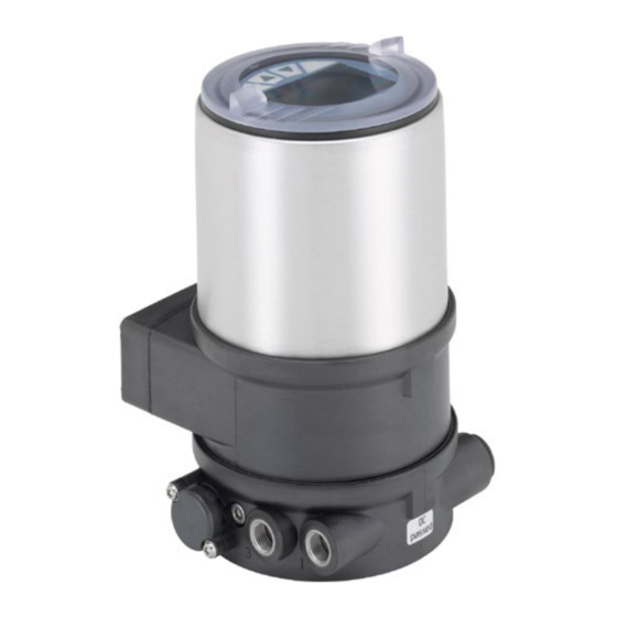
Alfa Laval 8692 Operating Instructions Manual (260 pages)
Electropneumatic positioner, Electropneumatic process controller
Brand:
Alfa Laval
| Category:
Valve Positioners
| Size: 3 MB
Table of Contents
Positioner Type 8692, 8693 T C Able of Contents
3
Table of Contents
3
General Information and Safety Instructions T C Able of Contents
7
General Information and Safety Instructions
7
Operating.instructions
8
Symbols
8
Authorized.use
9
Restrictions
9
Basic.safety.instructions
10
Contact.address
11
General.information
11
Master.code
11
Warranty
11
Type 8692, 8693 Description of System T C Able of Ontens
13
Description of System
13
Function.of.the.positioner.and.combination.with.valve.types
14
Models.of.the.positioner
15
Features.of.the.valve.types
16
Representation
17
Structure.of.the.positioner
17
Features
18
Function.diagram.of.the.positioner.with.single-Acting.actuator
19
Type.8692.Positioner.with.position.controller
20
Schematic.representation.of.the.positioner.type.8692
21
Properties.of.the.position.controller.software
22
Type.8693.Positioner.with.process.controller
24
Schematic.representation.of.the.process.control
25
Functions.of.the.process.controller.software
26
Interfaces.of.the.positioner.for.the.multipole.model
28
Interfaces.of.the.positioner.for.the.models.with.cable.gland
29
Safety.positions.after.failure.of.the.electrical.or.pneumatic.auxiliary.power
30
Technical.data
30
Factory.settings.of.the.positioner
31
Conformity
32
Electrical Data
32
Mechanical Data
32
Operating Conditions
32
Specifications.of.the.positioner
32
Standards
32
Pneumatic Data
33
Type Label
34
Control and Display Elements, Operating Modes T C Able of Contents
35
Configuration.of.the.keys
36
Control and Display Elements, Operating Modes
36
Control.and.display.elements
36
Control.and.display.elements.of.the.positioner
36
Information.on.the.display
38
Operating.modes
39
Automatic.operating.state.for.type.8692
40
Automatic.operating.state.for.type.8693
40
Manual.operating.state
42
Operating.levels
43
Switching.between.the.operating.levels
43
Type 8692, 8693 Installation T
45
Installation
47
Safety.instructions
47
Installation.of.the.positioner.type.8692.And.8693
48
On.process.valves.of.series.2103,.2300.And.2301
48
Installing.the.positioner.type.8694.And.type.8693
51
On.process.valves.belonging.to.series.26Xx.and.27Xx
51
Rotating.the.actuator.module
54
Process.valves.belonging.to.series.26Xx.and.27Xx
56
Rotating.the.positioner.for
56
Fluid.connection
57
Installation.of.the.process.valve
57
Safety.instructions
57
Pneumatic.connection.of.the.positioner
58
(Multi-POLE.MODEL)
59
Electrical.connection.24.V.DC.with.circular.plug-In.connector.(Multi-Pole.model)
59
Safety.instructions
59
Connection.of.the.position.controller.type.8692
60
Input Signals of the Control Centre (E.g. PLC) - Circular Plug M12, 8-Pole
60
Type.8692.-.Designation.of.the.circular.plug-In.connectors.and.the.contacts
60
Option: with Proximity Switch - Socket M8, 4-Pole
61
Output Signals to the Control Centre (E.g. PLC) - Circular Plug M12 - 8-Pole (Required for Analogue Output And/Or Binary Output Option Only)
61
Supply Voltage (Circular Plug M12 - 4-Pole)
61
Connection.of.the.process.controller.type.8693
62
Type.8693.-.Designation.of.the.circular.plug-In.connectors.and.the.contacts
62
Process Actual Value (Circular Plug M8, 4 Pole)
63
Setting.the.proximity.switch.-.Optional
64
Electrical.connection.24.V.DC.with.cable.gland
67
Safety.instructions
67
Input Signals from the Control Centre (E.g. PLC)
68
Terminal.assignment.for.cable.gland.-.Position.controller.type.8692
68
Terminal.board.of.the.positioner.with.screw.terminals.and.switches
68
Output Signals to the Control Centre (E.g. PLC) (Required for Analogue Output And/Or Binary Output Option Only)
69
Supply Voltage
69
Terminal.assignment.for.cable.gland.-.Process.controller.type.8693
70
Terminal Assignment When Selecting the Process Actual Value Input
71
Initial.start-Up
72
Installation
72
Safety.instructions
72
Specifying.the.basic.settings
72
Setting the Input Signal (Standard Signal)
73
Running the Automatic Adjustment X.TUNE
74
Overview of Operating Structure Initial Start-Up
75
Type 8692, 8693 Start-Up and Operation of the Position Controller Type 8692 T
77
Start-Up and Operation of the Position Controller Type 8692
77
Safety.instructions
79
Starting.up.and.installing.the.position.controller.type.8692
79
Description.of.the.procedure
80
Factory.settings.of.the.position.controller
81
Specifying.the.basic.settings
82
Description.of.the.basic.functions.in.the.main.menu
83
Main Menu of the Positioner
83
Inputting the Input Signal
84
Inputting the Operating Mode of the Pneumatic Actuator
84
Automatic Adjustment (X.TUNE) of the Position Controller
85
Adding Auxiliary Functions
86
Leaving the Main Menu
86
Operation.of.the.position.controller
87
Switching.between.the.operating.states
87
Automatic.operating.state
88
Meaning of the Keys
88
Switching.between.the.operating.levels
88
Information on the Display
89
Operating Structure
89
Information on the Display
90
Manual.operating.state
90
Meaning of the Keys
90
Operating Structure
91
Configuring.the.auxiliary.functions
92
Keys.at.the.configuration.level
92
Configuration.menu
93
Including Auxiliary Functions in the Main Menu
93
Switching between Process Operating Level and Configuration Level
93
Removing Auxiliary Functions from the Main Menu
94
Setting Numerical Values
94
Principle of Including Auxiliary Functions in the Main Menu
95
Auxiliary.functions
96
Overview of Auxiliary Functions for the Position Controller Type 8692
96
(Position Set-Point Value) and Stroke
97
CHARACT Select the Transfer Characteristic between Input Signal
97
CUTOFF Sealing Function for the Position Controller Type 8692
101
DIR.CMD Effective Sense of Direction of the Position Controller Set-Point Value
102
DIR.ACT Effective Sense of Direction of the Actuator
103
SPLTRNG Signal Split Range
104
X.LIMIT Limits the Mechanical Stroke Range
106
X.TIME Limiting the Control Speed
107
X.CONTROL Parameterisation of the Position Controller
108
SECURITY Code Protection for the Settings
110
SAFEPOS Input the Safety Position
112
SIG-ERROR Configuration of Signal Level Fault Detection
113
BINARY-IN Activation of the Binary Input
114
OUTPUT (Option) Configuring the Outputs
115
For the Position Set-Point Value
120
SET.FACTORY Resetting to the Factory Settings
122
SER. I\O Settings of the Serial Interface
123
Extras
124
Service
124
SIMULATION - in Process
124
Type 8692, 8693 Start-Up and Operation of the Position Controller Type 8693 T
125
Start-Up and Operation of the Position Controller Type 8693
126
Safety.instructions
127
Starting.up.and.setting.up.the.process.controller.type.8693
127
Description.of.the.procedure
128
Factory.settings.of.the.process.controller
129
Procedure.for.setting.up.a.process.control
129
Setting.up.the.position.controller
130
Setting.up.the.process.controller
130
Starting the P.CONTROL Auxiliary Function
130
Basic Settings for the P.CONTROL Function
131
DBND - Insensitivity Area (Dead Band) of the Process Controller
132
PARAMETER - Parameter Setting of the Process Controller
132
KP - Amplification Factor of the Process Controller
133
TN - Reset Time of the Process Controller
133
TV - Hold-Back Time of the Process Controller
133
FILTER - Filtering of the Process Actual Value Input
134
X0 - Working Point of the Process Controller
134
PV INPUT - Indication of the Signal Type for the Process Actual Value
135
PV-SCALE - Scaling of the Process Controller
135
SETUP - Setting up the Process Controller
135
(PV-INPUT 4 - 20 Ma)
136
(PV INPUT Frequency)
138
(Pv Input Pt 100)
141
SP INPUT - Type of Set-Point Value Default (Internal / External)
142
SP - SCALE - Scaling of the Position Controller
143
P.CO INIT - Setting the Smooth Switchover between MANUAL and AUTOMATIC Mode
144
P.Q'LIN - Linearization of the Process Characteristic
145
Operating Mode
146
Operation
146
P.TUNE - Self-Optimization of the Process Controller (Process Tune)
146
Start the P.TUNE Function
147
Self-Optimization Sequence of the Process Controller
148
Operation.of.the.process.controller
149
Switching.between.the.operating.states
149
Automatic.operating.state
150
Meaning of the Keys
150
Switching.between.the.operating.levels
150
Information on the Display
151
Operating Structure
151
Manual.operating.state
152
Manually Changing the Process Set-Point Value
152
Meaning of the Keys
152
Information on the Display
153
Operating Structure
153
Auxiliary.functions.for.the.process.controller
154
Overview.of.the.auxiliary.functions
154
Including Auxiliary Functions in the Main Menu
155
Removing Auxiliary Functions from the Main Menu
155
CUTOFF - Sealing.function.for.the.position.controller.type.8693
156
SECURITY - Code.protection.for.the.settings
158
SIG-ERROR - Configuration.of.signal.level.fault.detection
160
Output.(Option).-.Configuring.the.outputs
162
CAL.USER - Calibrating.the.actual.value.display.and.the.inputs.for.the.process.values
168
SIMULATION - In Process
172
Type 8692, 8693 Profibus-Dp T
173
Profibus-Dp
173
General.information
174
Technical.data
174
Interfaces
175
Safety.settings.if.the.bus.fails
175
Connection.diagram.type.8692
176
Electrical.connections
176
Bus.connection.(Round.socket/Plug.m12,.5-Pole)
177
Connection.diagram.type.8693
177
Supply.voltage.(Circular.plug.m12,.4-Pole)
177
Process.actual.value.(Circular.plug.m8,.4-Pole).-.Only.type.8693
178
Settings.on.the.positioner
179
BUS.COMM Menu for Type 8692
181
Explanations.of.the.menu.options.in.the.bus.comm.menu
181
BUS.COMM Menu for Type 8693
182
Configuration.in.the.profibus-Dp.master
184
Configuration.of.the.process.values
184
Functional.deviations.from.the.standard.model
184
Bus.status.display
187
Configuration.with.siemens.step7
188
Example.1.For.a.position.controller.(Type.8692)
188
Transfer.of.nominal.and.actual.values
188
Example.2.For.a.position.controller.(Type.8693)
190
Transfer.of.several.process.values
190
Type 8692, 8693 Devicenet T
191
Devicenet
191
Definition.of.terms
193
General.information
193
Technical.data
194
Interfaces
195
Safety.settings.if.the.bus.fails
195
Connection.diagram.type.8692
196
Electrical.connections
196
Bus.connection.(Circular.plug.m12,.5-Pole)
197
Connection.diagram.type.8693
197
Supply.voltage.(Circular.plug.m12,.4-Pole)
197
Process.actual.value.(Circular.plug.m8,.4-Pole).-.Only.type.8693
198
Network.topology.of.a.devicenet.system
199
Terminating.circuit.for.devicenet.systems
199
Settings.on.the.positioner.in.the.main.menu
200
Explanations.of.the.menu.options.in.the.bus.comm.menu
202
Functional.deviations.from.the.standard.model
203
Configuration.of.the.process.data
204
Static.input.assemblies
204
Static.output.assemblies
206
Bus.status.display
207
Address.assignment
208
Configuration.example.1
208
Installation.of.the.eds.file
208
Offline.parameterization.of.the.device
209
Online.parameterization.of.the.device
210
Type 8692, 8693 Maintenance and Troubleshooting T
213
Maintenance
214
Safety.instructions
214
Service.at.the.air.intake.filter
215
Error.messages.and.malfunctions.type.8692
216
Error.messages.on.the.display
216
General Error Messages
216
Error Messages While the X.TUNE Function Is Running
217
Other.malfunctions
217
Error.messages.and.malfunctions.type.8693
218
Error.messages.on.the.display
218
General Error Messages
218
Error Messages While the P.Q'LIN Function Is Running
219
Error Messages While the X.TUNE Function Is Running
219
Error Messages on Field Bus Devices
220
Error Messages While the P.TUNE Function Is Running
220
Other.malfunctions
221
General Rules (Appendix) T
231
P.portion
234
Properties.of.pid.controllers
234
I.portion
235
D Portion with Delay
236
D.portion
236
Function of the Real PID Controller
237
Superposition.of.p,.I.and.D.portions
237
Implemented.pid.controller
238
Adjustment.rules.according.to.ziegler.and.nichols.(Oscillation.method)
240
Adjustment.rules.for.pid.controllers
240
Adjustment.rules.according.to.chien,.Hrones.and.reswick
242
Advertisement
Alfa Laval 8692 Quick Start Manual (112 pages)
Positioner / Process Controller
Brand:
Alfa Laval
| Category:
Valve Positioners
| Size: 2 MB
Table of Contents
English
3
Table of Contents
3
Quickstart
5
Symbols
5
Authorized Use
6
Restrictions
6
Predictable Misuse
6
Basic Safety Instructions
7
General Information
8
Contact Address
8
Warranty
8
Description Of System
9
Technical Data
10
Functions
10
Conformity
10
Standards
10
Operating Conditions
10
Mechanical Data
11
Type Label
11
Pneumatic Data
11
Electrical Data
12
Control And Display Elements
13
Function of the Keys
13
Operating State
14
Operating Levels
14
Installation
15
Display in Operating State AUTOMATIC
15
Safety Instructions
15
Installing the Positioner / Process Controller on Process Valves Belonging to Series 2103 and 23Xx
16
Installing the Positioner / Process Controller on Process Valves Belonging to Series 26Xx and 27Xx
17
Fluid Installation
19
Safety Instructions
19
Installing the Process Valve
19
Pneumatic Connection of the Positioner / Process Controller
19
Electrical Installation
21
Safety Instructions
21
Electrical Installation 24 V DC
21
Electrical Installation PROFIBUS DP
27
Electrical Installation Devicenet
29
Start-Up Type 8692
31
Safety Instructions
31
Specifying the Basic Settings
32
Automatic Adjustment X.TUNE
34
Start-Up Type 8693
35
Accessories
35
Safety Positions
36
Packaging, Transport, Storage
37
Deutsch
39
Darstellungsmittel
41
Der Quickstart
41
Beschränkungen
42
Bestimmungsgemässe Verwendung
42
Vorhersehbarer Fehlgebrauch
42
Grundlegende Sicherheitshinweise
43
Allgemeine Hinweise
44
Gewährleistung
44
Kontaktadresse
44
Systembeschreibung
45
Betriebsbedingungen
46
Funktionen
46
Konformität
46
Normen
46
Technische Daten
46
Mechanische Daten
47
Pneumatische Daten
47
Typschild
47
Elektrische Daten
48
Bedien- Und Anzeigeelemente
49
Funktion der Tasten
49
Bedienebenen
50
Betriebszustand
50
Anzeige IM Betriebszustand AUTOMATIK
51
Montage
51
Sicherheitshinweise
51
Montage Positioner / Prozessregler an Prozessventile der Reihe 2103, 2300 und 2301
52
Montage Positioner / Prozessregler an Prozessventile der Reihe 26Xx und 27Xx
53
Fluidische Installation
55
Installation Prozessventil
55
Pneumatischer Anschluss des Positioners / Prozessreglers
55
Sicherheitshinweise
55
Elektrische Installation
57
Elektrische Installation 24 V DC
57
Sicherheitshinweise
57
Elektrische Installation PROFIBUS DP
63
Elektrische Installation Devicenet
65
Inbetriebnahme Typ 8692
67
Sicherheitshinweise
67
Festlegen der Grundeinstellungen
68
Automatische Anpassung (X.TUNE)
70
Inbetriebnahme Typ 8693
71
Zubehör
71
Sicherheitsstellungen
72
Transport, Lagerung, Verpackung
73
Français
75
Quickstart
77
Symboles
77
Mauvaise Utilisation Prévisible
78
Restrictions
78
Utilisation Conforme
78
Consignes De Sécurité Fondamentales
79
Adresse
80
Garantie Légale
80
Indications Générales
80
Description Du Système
81
Caractéristiques Techniques
82
Conditions D'exploitation
82
Conformité
82
Fonctions
82
Normes
82
Caractéristiques Mécaniques
83
Caractéristiques Pneumatiques
83
Étiquette
83
Caractéristiques Électriques
84
Elements De Commande Et D'affichage
85
Fonction des Touches
85
Etat de Marche
86
Niveaux de Commande
86
Affichage en État de Marche AUTOMATIQUE
87
Consignes de Sécurité
87
Montage
87
Montage du Positionneur Type 8692 Et Type 8693 Sur Les Vannes Process des Séries 2103 Et 23Xx
88
Montage du Positionneur Type 8692 Et Type 8693 Sur Les Vannes Process des Séries 26Xx Et 27Xx
89
Consignes de Sécurité
91
Installation Fluidique
91
Installation de la Vanne Process
91
Raccordement Pneumatique du Positionneur
91
Consignes de Sécurité
93
Installation Électrique
93
Installation Électrique 24 V DC
93
Installation Électrique PROFIBUS DP
100
Installation Électrique Devicenet
102
Consignes de Sécurité
104
Détermination des Réglages de Base
104
Mise En Service Type 8692
104
Adaptation Automatique X.TUNE
106
Accessoires
108
Mise En Service Type 8693
108
Positions De Sécurité
109
Emballage, Transport, Stockage
110
Advertisement
Related Products
Alfa Laval 8693
Alfa Laval 862W-227
Alfa Laval B MRPX 818HGV-14C
Alfa Laval B BRPX 818HGV-34C
Alfa Laval H MRPX 818HGV-74C
Alfa Laval ThinkTop Digital 8
Alfa Laval 881145-09-01/7
Alfa Laval ThinkTop Digital 8-30 VAC NO/NC
Alfa Laval 881176-09-01/1
Alfa Laval 8010014918
Alfa Laval Categories
Control Unit
Industrial Equipment
Water Pump
Water Filtration Systems
Cleaning Equipment
More Alfa Laval Manuals
Login
Sign In
OR
Sign in with Facebook
Sign in with Google
Upload manual
Upload from disk
Upload from URL