Sign In
Upload
Manuals
Brands
AIRTRONICS Manuals
Video Game Controller
M12S SUPER
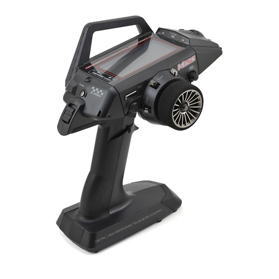
AIRTRONICS M12S SUPER Radio System Manuals
Manuals and User Guides for AIRTRONICS M12S SUPER Radio System. We have
1
AIRTRONICS M12S SUPER Radio System manual available for free PDF download: User Manual
AIRTRONICS M12S SUPER User Manual (133 pages)
Telemetry System with Sanwa Synchronized Link Support 2.4GHZ FH4T RADIO CONTROL SYSTEM
Brand:
AIRTRONICS
| Category:
Video Game Controller
| Size: 22 MB
Table of Contents
Table of Contents
2
Packaging
2
Safety
3
Service and Support
3
FCC Compliance Statement
3
2.4Ghz Frequency Band Precautions
4
Transmitter Precautions
4
Receiver Precautions
4
Servo Connectors
4
System Features
5
What's Included
5
System Specifications
5
Transmitter Overview Diagrams
6
Bind LED Condition Indicator
8
Receiver Overview, Connections and Mounting
8
Transmitter and Receiver Overview Diagram Descriptions
8
LED Condition Indicators
10
Audible Warning Alarms
10
Inactivity (Power ON) Alarm
10
Transmitter LED Condition Indicators and Warning Alarms
10
Low Voltage Alert Alarm
11
Charging the Transmitter Battery Pack
11
Installing the Transmitter Battery Pack
11
Transmitter Battery Options
11
Steering Wheel and Throttle Trigger Tension Adjustment
12
Optional Steering Wheel Spring Installation
12
Steering Wheel Travel Adjustment
12
Throttle Trigger Cover Installation
12
Optional Steering Wheel Installation
13
Optional Grip Installation
13
Throttle Trigger Angle Adjustment
13
Wrist Strap Anchor Installation
13
Throttle Trigger Position Adjustment
14
Optional Steering Wheel Offset Plate Installation
14
Installation Without Steering Wheel Offset Plate
15
Installation with Steering Wheel Offset Plate
15
Optional Steering Wheel Angle Plate Installation
15
Activating the Left Side Switches
16
Changing the Programming Cursor Scroll Direction
16
Driving Position Adjustment
16
Programming Overview and Functions
17
Display Screens Overview
17
STATUS Screen Overview Diagram
18
STATUS Screen Overview Diagram Descriptions
18
Menus Structure Overview
19
Menus Overview
20
TELEMETRY Screen Overview Diagram Descriptions
21
Telemetry Screen Overview
21
Reviewing Telemetry Data
22
Transmitter and Receiver Binding
23
Basic Mode Menu Overview
25
Turning Basic Mode on and off
25
System Menu Overview
27
Includes System Menu Programming Contents
27
Model Select
28
Selecting a Model
28
Model Name
29
Entering a Model Name
29
Deleting a Character
30
Deleting a Model Name
30
Model Copy
30
Copying Model Programming Data
30
Model Clear
31
Clearing Model Programming Data
31
Model Sort
32
Sorting Models
32
Model Template
32
Copying a Model Template
33
Using the Direct Model Select Function
34
Changing Direct Model Select Models
34
Turning the Telemetry Function on and off
35
Changing the Safety Link Number
35
Changing the Channel Response Mode
36
Response Mode Leds
36
Binding the Transmitter and Receiver
36
Assign Menu
37
Using the Servo Monitor
37
Push-Button Switch Function Assignments
37
Changing the Push-Button Switch Function Assignments
37
Changing the Switch Mode
39
Trim Switch Function Assignments
39
Changing the Trim Switch Function Assignments
39
Changing the Trim Switch Step Value
40
Changing the Trim Switch Direction of Travel
40
Auxiliary Dial Function Assignments
41
Changing the Auxiliary Dial Function Assignment
41
Changing the Auxiliary Dial Step Value
41
Changing the Auxiliary Dial Direction of Travel
42
Auxiliary Lever Function Assignments
42
Changing the Auxiliary Lever Function Assignment
42
Changing the High and Low Tweak Values
42
Telemetry Function Assignments
43
Changing the Telemetry Value
43
Changing the Telemetry Lever Control Function and Tweak Values
45
Buzzer Menu
46
Vibrator Menu
47
Changing the Audible Tones
47
Changing the Volume
47
LCD Menu
48
Adjusting the Vibration Level
48
Turning Vibration Functions on and off
48
Changing the LCD Contrast
49
Changing the LCD Backlight Brightness
49
Changing the LCD Backlight Mode
49
Changing the LCD Backlight Color
49
Aux Type Mode
50
Changing the Auxiliary Channel Operating Mode
50
Changing the Number of Points Value
50
Trim Type Menu
51
TH Type Menu
51
Changing the Trim Type
51
Calibration Menu
52
Changing the Throttle Type
52
Calibrating the Steering, Throttle and Auxiliary Lever Controls
53
Batt Menu
54
Resetting Steering, Throttle and Auxiliary Lever Calibration Values
54
Changing the Low Voltage Alert Alarm Value
55
Changing the Low Voltage Limit Alarm Value
55
Log Setup Menu
56
Changing the Throttle Slow Value
56
Telemetry Data Recording
56
Turning Telemetry Data Recording on and off
56
RPM and Speed Telemetry Data Display Options
57
Changing the RPM Unit Value
57
Changing the Maximum Scale Value
57
Calibrating the RPM Sensor - Changing the Ratio Value
58
Calibrating the RPM Sensor - Changing the 10Count Distance Value
58
Battery Low Voltage Telemetry Data Display and Alert Alarm Options
59
Changing the Maximum Voltage Value
59
Changing the Alert Voltage Value
60
Telemetry 1 and Telemetry 2 Data Display and Alert Alarm Options
60
Changing the Telemetry Name
60
Changing the Unit Value
61
Changing the Unit Name (Custom Unit Value Only)
61
Changing the Rate and the Offset Values
61
Changing the Maximum Value
62
Changing the Alert Value
62
Changing the Minimum Value
63
Changing the Message Name and Message Pop-Up Behavior
63
Receiver Mode
64
Enabling Receiver Mode
64
Steering and Throttle Output Data Display Adjustments
65
Calibrating the Steering Output Data Display
65
Calibrating the Throttle Output Data Display
65
Entering a User Name
66
Deleting the User Name
67
Downloading the PC LINK Manager Software
67
Saving the Telemetry Data Log
67
Saving Model Programming Data
68
Loading Model Programming Data
69
Saving Model Templates
69
Saving a Model Template
69
Loading Model Templates
70
Updating Transmitter Firmware
70
Updating the Transmitter Firmware Version
71
Resetting the On-Time
71
Changing the Boot Options
72
Setup Menu Overview
73
Includes Setup Menu Programming Contents
73
Changing the Servo Sub-Trim Values
74
Changing the Servo Reversing Values
75
Changing the Auxiliary 1 Point Values
76
Changing the Auxiliary 2 Point Values
77
Choosing the Motor on Axle Power Distribution Values
78
Controlling the Motor on Axle Mixing Function
78
Choosing the Four Wheel Steering Mixing Options
79
Controlling the Four Wheel Steering Mixing Function
80
Changing Steering and Throttle Response Time Values
80
Choosing the Fail Safe Settings
81
Checking the Fail Safe Settings
81
Choosing the Receiver Battery Voltage Value
81
Activating the Receiver Battery Voltage Fail Safe Function
82
Setting the Goal Time
83
Setting the Pre-Alarm Time
83
Choosing the Optional Throttle Trigger Start
83
Starting the Lap Timer and Counting Lap Times
83
Stopping the Lap Timer
84
Viewing Lap Times
84
Setting the Interval Timer
84
Starting the Interval Timers
85
Stopping the Interval Timers
85
Setting the Finish Time
85
Starting the Countdown Timer
86
Stopping the Countdown Timer
86
Racing Menu Overview
87
Includes Racing Menu Programming Contents
87
Turning Racing Mode on and off
88
Turning Separate Functions on and off
88
Switching Racing Modes to Program Separate Functions
88
D/R Menu
89
Trim Menu
89
Changing the Dual Rate Percentage Values:
89
Curve Menu
90
Changing the Trim Values
90
Exponential Programming
91
Choosing the Channel and the Curve Type
91
Changing the Rate Percentage Value
91
Changing the Steering Tweak Right and Tweak Left Values
92
Adjustable Rate Control Programming
92
Changing the Point Value
93
Point Curve Programming
93
Changing the Point Percentage Values
94
Choosing the Channel
95
Changing the Servo Speed Forward Value
95
Changing the Servo Speed Return Value
95
Changing the Point Percentage and in and out Values
96
Changing the Stroke Percentage Value
97
Changing the Point Percentage Value
97
Changing the Release and Hold Values
97
Changing the Lag Value
98
Changing the Position Percentage Value
98
Turning the Throttle Offset Function on and off
98
Changing the Brake Lock Percentage Value
99
Changing the Brake Delay Percentage Value
99
Changing the Hold Percentage Value
100
Turning the Throttle Hold Function on and off
100
Changing the Brake Lock-Out Value
100
Changing the Master Channel
102
Changing the Slave Channel
103
Changing the Rate 1 and Rate 2 Percentage Values
103
Changing the Channel Offset Value
103
Changing the Master Telemetry Data Option
105
Changing the Telemetry Type
105
RPM to AUX2 Mixing
106
TLM1 Alert to TH Mixing
106
Changing the Toe Angle Values
107
Changing the Ackerman Angle Percentage Values
107
Changing the Racing Mode Delay Percentage Values
108
Changing the Code Function Names
109
Changing the Code Auxiliary Values
109
Custom Menu Overview
109
Includes Custom Menu Programming Contents
110
Changing Function Programming Values
110
Adding Programming Menus to the CUSTOM Menu
110
Removing Programming Menus from the CUSTOM Menu:
111
Troubleshooting Guide
111
Racing Mode Functions by Car Type Table
113
Trim Switch, Aux Dial and Aux Lever Functions Table
114
Glossary of Terms
116
Index
121
Advertisement
Advertisement
Related Products
AIRTRONICS M12
AIRTRONICS MX-V
AIRTRONICS MX-Sport
AIRTRONICS MX-3X
AIRTRONICS MT-4 S
AIRTRONICS M11X FHSS-3
AIRTRONICS MT-S
AIRTRONICS M11
AIRTRONICS MT-4
AIRTRONICS M11X
AIRTRONICS Categories
Remote Control
Transmitter
Receiver
Toy
Control Systems
More AIRTRONICS Manuals
Login
Sign In
OR
Sign in with Facebook
Sign in with Google
Upload manual
Upload from disk
Upload from URL