Sign In
Upload
Manuals
Brands
Ahlborn Manuals
Measuring Instruments
ALMEMO 204
Ahlborn ALMEMO 204 Manuals
Manuals and User Guides for Ahlborn ALMEMO 204. We have
2
Ahlborn ALMEMO 204 manuals available for free PDF download: Operating Instructions Manual
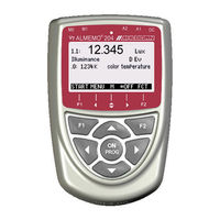
Ahlborn ALMEMO 204 Operating Instructions Manual (76 pages)
V7 special measuring instrument for digital sensors
Brand:
Ahlborn
| Category:
Measuring Instruments
| Size: 2 MB
Table of Contents
Operating Controls
2
Table of Contents
3
General
7
Warranty
7
Standard Delivery
8
Waste Disposal
8
Safety Instructions
9
Special Notes on Use
10
Handling Batteries / Rechargeable Batteries Correctly
10
Introduction
11
Functions of the ALMEMO ® 202-S and ALMEMO ® 204
12
Sensor Programming
12
Measuring Operation
13
Process Control
14
Putting into Service
17
Power Supply
18
Battery Operation and Supply Voltage Monitoring
18
Mains Operation
18
External DC Voltage Supply
18
Sensor Supply
19
Switching on / OFF, Reinitialization
19
Data Buffering
19
Connecting Sensors / Transducers
20
Standard Sensor (V5)
20
D6 Sensors
20
D7 Sensors
20
Measuring Inputs und Additional Channels
21
Potential Separation
21
Display and Keypad
22
Display and Menu Selection
22
Measured Value Display and Status Symbols
22
Function Keys
23
Function Selection
24
To Enter Data
24
Menu Selection
26
Measuring Menus
27
Sensor Display Menu
27
Measuring Channel Selection
27
Measured Value Correction and Compensation
27
Setting Measured Values to Zero
28
Atmospheric Pressure Compensation
28
Measuring Points List Menu
29
User Menu U2 - Data Logger
29
Measured Data Scanning and Output
30
Usermenus
31
Functions
31
Configuration of User Menus
32
Functions Menus
34
Maximum, Minimum, Individual Value Memory
34
Averaging
35
Smoothing Meas. Values by Means of a Sliding Average
35
Averaging over Manually Selected Meas. Operations
36
Averaging over Time
37
Averaging over a Cycle
37
Averaging over Measuring Points
38
Volume Flow Measurement
38
Two-Point Adjustment with Setpoint Entry
39
Scaling
39
Data Logger Functions
40
Internal Data Memory
40
External Plug-In Memory Incorporating Memory Card
40
Numbering of Measuring Operations
41
Once-Only Saving of All Measuring Points
41
Cyclic Saving of All Measuring Points
42
Memory Capacity, Memory Output and Clearing
42
Scanning Configuration
43
Scan Mode
43
Starting and Stopping Measuring Operations
45
Sensor Programming
47
Selecting the Input Channel
47
Channel Designation
47
Averaging Mode
48
Locking the Sensor Programming
48
Limit Values
48
Correction Values
49
Scaling, Decimal Point Setting
49
Changing the Units
50
Selecting the Measuring Range
50
Sensor Configuration
52
Multi-Point Calibration
52
Special Functions
52
Cycle Factor
53
Actions Triggered by Limit Value Infringement
53
Analog Output Start / End
54
Minimum Sensor Supply Voltage
54
Output Function
55
Reference Channels
55
Element Flags
56
Device Configuration
57
Date and Time-Of-Day
57
Device Designation
57
Language
57
Illumination and Contrast
57
Interface, Device Address and Networking
58
Baud Rate, Data Format
58
Process Control
59
Sampling Rate
59
Scan Cycle
59
Output Cycle
60
Hysteresis
60
Operating Parameters
60
Output Modules
61
Data Cable
61
Relay Trigger Modules
61
Analog Outputs
63
Trouble-Shooting
65
Declaration of Conformity
67
Annex
69
Technical Data
69
Product Overview
70
Index
71
Your Contact
75
Advertisement
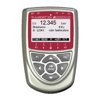
Ahlborn ALMEMO 204 Operating Instructions Manual (72 pages)
Special measuring instrument for digital sensors
Brand:
Ahlborn
| Category:
Measuring Instruments
| Size: 3 MB
Table of Contents
1 Operating Controlse
2
Table of Contents
3
Table of Contents
5
2 General
6
Warranty
6
Standard Delivery
7
Waste Disposal
7
3 Safety Instructions
8
Special Notes on Use
9
Handling Batteries / Rechargeable Batteries Correctly
9
4 Introduction
10
Functions of the ALMEMO 204
11
Sensor Programming
11
Measuring Operation
12
Process Control
13
5 Putting into Service
16
6 Power Supply
17
Battery Operation and Supply Voltage Monitoring
17
Mains Operation
17
External DC Voltage Supply
17
Sensor Supply
18
Switching on / OFF, Reinitialization
18
Data Buffering
18
7 Connecting Sensors / Transducers
18
Standard Sensor (V5)
19
D6 Sensors
19
D7 Sensors
19
Measuring Inputs und Additional Channels
20
Potential Separation
20
8 Display and Keypad
21
Display and Menu Selection
21
Measured Value Display and Status Symbols
21
Function Keys
22
Function Selection
23
To Enter Data
23
9 Menu Selection
25
10 Measuring Menus
26
Sensor Display Menu
26
Measuring Channel Selection
26
Measured Value Correction and Compensation
26
Setting Measured Values to Zeron
27
Atmospheric Pressure Compensation
27
Measuring Points List Menu
28
User Menu U2 - Data Logger
28
11 Measured Data Scanning and Output
29
12 Usermenus
29
Functions
30
Configuration of User Menus
31
13 Functions Menus
32
Maximum, Minimum, Individual Value Memory
32
Averaging
33
Smoothing Meas. Values by Means of a Sliding Average
33
Averaging over Manually Selected Meas. Operations
34
Averaging over Time
35
Averaging over a Cycle
35
Averaging over Measuring Points
36
Volume Flow Measurement
36
Two-Point Adjustment with Setpoint Entry
37
Scaling
37
Data Logger Functions
38
Internal Data Memory
38
External Plug-In Memory Incorporating Memory Card
38
Numbering of Measuring Operations
39
Once-Only Saving of All Measuring Points
39
Cyclic Saving of All Measuring Points
40
Memory Capacity, Memory Output and Clearing
40
Scanning Configuration
41
Scan Mode
41
Starting and Stopping Measuring Operations
43
14 Sensor Programming
45
Selecting the Input Channel
45
Channel Designation
45
Averaging Mode
46
Locking the Sensor Programming
46
Limit Values
46
Correction Values
47
Scaling, Decimal Point Setting
47
Changing the Units
48
Selecting the Measuring Range
48
Sensor Configuration
49
Multi-Point Calibration
50
Special Functions
50
Cycle Factor
50
Actions Triggered by Limit Value Infringement
51
Analog Output Start / End
52
Minimum Sensor Supply Voltage
52
Output Function
52
Reference Channels
53
Element Flags
53
15 Device Configuration
54
Date and Time-Of-Day
54
Device Designation
54
Language
54
Illumination and Contrast
54
Interface, Device Address and Networking
55
Baud Rate, Data Format
55
Process Control
56
Sampling Rate
56
Scan Cycle
56
Output Cycle
57
Hysteresis
57
Operating Parameters
57
16 Output Modules
58
Data Cable
58
Relay Trigger Modules
58
Analog Outputs
60
17 Trouble-Shooting
62
18 Declaration of Conformity
63
19 Annex
64
Technical Data
64
Product Overview
64
Index
66
Your Contact Partner
70
Advertisement
Related Products
Ahlborn ALMEMO 202-S
Ahlborn ALMEMO 2390-5
Ahlborn ALMEMO 2590-4S
Ahlborn ALMEMO 2490-1
Ahlborn ALMEMO 2470-1S
Ahlborn ALMEMO 2470-2S
Ahlborn ALMEMO 2450-1L
Ahlborn ALMEMO 2590-2A
Ahlborn ALMEMO 2490-1A
Ahlborn ALMEMO 2290-2/3
Ahlborn Categories
Measuring Instruments
Data Loggers
Accessories
Transmitter
Switch
More Ahlborn Manuals
Login
Sign In
OR
Sign in with Facebook
Sign in with Google
Upload manual
Upload from disk
Upload from URL