Sign In
Upload
Manuals
Brands
AGTRON Manuals
Monitor
ART 260
AGTRON ART 260 Crop input controller Manuals
Manuals and User Guides for AGTRON ART 260 Crop input controller. We have
2
AGTRON ART 260 Crop input controller manuals available for free PDF download: Operator's Manual
AGTRON ART 260 Operator's Manual (48 pages)
Single and Dual Loop Rate & Blockage System
Brand:
AGTRON
| Category:
Monitor
| Size: 1 MB
Table of Contents
1 Quick Start Guide
3
2 Flow Chart
4
Follow Safety Instructions
5
3 Table of Contents
6
4 Introduction
7
How Your Rate and Blockage Monitor Works
7
The User Interface
7
5 Installation
9
Monitor Installation
9
Cable Ties and Main Extension Cable Installation
9
Seed Sensor and Sensor Loop Cable Installation
10
Y-Cable Installation
11
Figure 5-9. Installation Diagram 1
12
Figure 5-10. Installation Diagram 2 (Less than 60 Sensors)
13
Figure 5-11. Installation Diagram 3 (more than 60 Sensors)
14
Optional Sensor Installation
15
Figure 5-12. Installation (Sensor Breakout Cable)
19
Figure 5-13. Installation (ART Loop Terminator)
20
6 Setup
21
Optional Sensor Setup
22
Speed Setup
22
Test Speed Setup
23
Work Switch Setup
23
Shaft Setup
24
Fan Setup
25
Bin Setup
26
Meter Setup
26
7 Operation
27
Blockage
27
Rate Units
27
Rate
28
High and Low Rate Alarms
28
Turning Loops on and off
29
Speed Mode
29
Area Mode
29
Distance Mode
29
Shaft Mode
30
Fan Mode
30
Bin Mode
30
Meter Mode
30
Diagnostic Modes
31
8 Diagnostics and Troubleshooting
32
Troubleshooting Table
32
9 Appendix
37
Appendix A: Parts List
37
Appendix B: Optional Sensors
38
Appendix C: Monitor Display Messages
40
Appendix D: Seed Sensor Sensitivity Values
41
Appendix E: Conversion Factors
42
Appendix F: Default Calibration Values
43
Appendix G: ART Toolbar Sensor Breakout Connector Pin-Out
44
Appendix H: DB9 (9 Pin) Connector Pin-Out
44
Appendix I: Deutsch DTM Connector Pin-Out
44
10 Notes
45
11 Warranty
46
Warranty Guidelines
46
Advertisement
AGTRON ART 260 Operator's Manual (43 pages)
Rate & Blockage Monitors
Brand:
AGTRON
| Category:
Monitor
| Size: 1 MB
Table of Contents
Quick Start Guide
3
Table of Contents
5
Introduction
6
How Your Rate and Blockage Monitor Works
6
The User Interface
6
Installation
8
Monitor Head Installation
8
Seed Sensor Installation
9
Y-Cables and Sensor Loop Cables
9
Installation Diagram (ART Loop Terminator)
11
Installation Diagram (Less than 60 Sensors)
12
Installation Diagram (more than 60 Sensors)
13
Setup
14
GPS Speed Sensor
15
Radar Speed Sensor
16
Wheel Speed Sensor
16
Test Speed
17
Manual Work Switch
18
Automatic Work Switch
19
Shaft Sensor
20
Fan Sensor
21
Bin Sensor
21
Meter Sensor
22
Installation Diagram (Sensor Breakout Cable)
23
Operation
24
Rate Units
24
Blockage Mode
24
Rate Mode
24
High and Low Rate Alarms
25
Turning Loops on and off
25
Additional Operational Modes
25
Diagnostics and Troubleshooting
28
Troubleshooting Table
28
Diagnostic Modes
32
Reference
34
Monitor Display Messages
34
Seed Sensor Sensitivity Values
35
Conversion Factors
36
Default Calibration Values
37
Sensor Breakout Connector Pin-Out
38
DB9 Connector Pin-Out
38
DTM Connector Pin-Out
38
Parts List
39
Menu Navigation Flow Chart
40
Notes
41
Warranty
42
Warranty Guidelines
42
Advertisement
Related Products
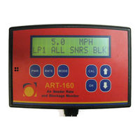
AGTRON ART 160
AGTRON ART 100
AGTRON Categories
Measuring Instruments
Monitor
Accessories
More AGTRON Manuals
Login
Sign In
OR
Sign in with Facebook
Sign in with Google
Upload manual
Upload from disk
Upload from URL