Table of Contents
Advertisement
Quick Links
Download this manual
See also:
Operator's Manual
Advertisement
Table of Contents

Related Manuals for AGTRON ART 160

Summary of Contents for AGTRON ART 160
- Page 1 Quick Start ART 160 and ART 260 Rate & Blockage Monitors Operator’s Manual MNRT02606 for Software Revision 2.9B ART 160 and ART 260 Rate & Blockage Monitors - Operator’s Manual Page 3...
- Page 2 Table of Contents Page 2 ART160 and ART260 Rate & Blockage Monitors - Operator’s Manual...
-
Page 3: Quick Start Guide
(If you have seed and fertilizer in the same loop set the total LBS/AC for seed and fertilizer together) You must be on the RATE screen in order to hear alarms. ART 160 and ART 260 Rate & Blockage Monitors - Operator’s Manual Page 3... - Page 4 Agtron Enterprises Inc. will not accept any responsibility for any damage or malfunctions resulting from failure to comply with the operator’s manual. If you do not understand the information in this manual, or if you have any questions, contact Agtron Enterprises Inc. Customer Service. ...
-
Page 5: Table Of Contents
DB9 Connector Pin-out ..................38 DTM Connector Pin-out ..................38 Parts List ......................39 Menu Navigation Flow Chart ................40 Notes ....................41 Warranty ................... 42 Warranty Guidelines .................... 42 ART 160 and ART 260 Rate & Blockage Monitors - Operator’s Manual Page 5... -
Page 6: Introduction
Loop automatically. A maximum of 120 sensors can be connected in a Loop. Additional sensors for shafts, bin and fan monitoring can be added. (Six for the ART 160 and nine for the ART 260.) Each sensor connects directly to the monitor. The User Interface... - Page 7 Distance and Area KSEED/LB, SEED FACTOR will be set for each Loop using the Seed Rate Wizard. Select high/low alarm modes; Enter calibration values RATE ART 160 and ART 260 Rate & Blockage Monitors - Operator’s Manual Page 7...
-
Page 8: Installation
3. Secure the Main Harness Extension to the equipment with cable ties, the pins. allowing enough slack for hitch movement. To help avoid electrical interference problems, create a figure eight shape with ex cess cable before securing. Page 8 ART 160 and ART 260 Rate & Blockage Monitors - Operator’s Manual... -
Page 9: Seed Sensor Installation
3. Connect the first Y-Cable’s female Sensor Loop Cable to the last Seed Sensor using Sensor Loop Cables as needed. ART 160 and ART 260 Rate & Blockage Monitors - Operator’s Manual Page 9... - Page 10 2. Attach blue ties for all Loop 1 cables. rope only enough to stop the swinging motion. 3. Attach yellow ties for all Loop 2 cables. Page 10 ART 160 and ART 260 Rate & Blockage Monitors - Operator’s Manual...
-
Page 11: Installation Diagram (Art Loop Terminator)
The terminator has a red LED to indicate power is on. Tip: A Y-Cable with the Seed Sensor connections mated together can be substituted for the terminator ART 160 and ART 260 Rate & Blockage Monitors - Operator’s Manual Page 11... -
Page 12: Installation Diagram (Less Than 60 Sensors)
Installation Installation Diagram (Less than 60 sensors) Page 12 ART 160 and ART 260 Rate & Blockage Monitors - Operator’s Manual... -
Page 13: Installation Diagram (More Than 60 Sensors)
Installation Installation Diagram (More than 60 sensors) ART 160 and ART 260 Rate & Blockage Monitors - Operator’s Manual Page 13... -
Page 14: Setup
3. Repeat the preceding procedure for Loop 2. Page 14 ART 160 and ART 260 Rate & Blockage Monitors - Operator’s Manual... -
Page 15: Gps Speed Sensor
4. Press CAL and set the Distance Check value to agree with the distance driven (from 0.1 to 9999999.9) using the UP and DOWN arrows. The Circumference value is modified when editing the Distance Check value. ART 160 and ART 260 Rate & Blockage Monitors - Operator’s Manual Page 15... -
Page 16: Radar Speed Sensor
Sensor Breakout Cable and Speed Sensor are required. 3. From the main RATE screen, press MODE. 4. Press CAL several times until the SELECT SNR CH # screen appears. Page 16 ART 160 and ART 260 Rate & Blockage Monitors - Operator’s Manual... -
Page 17: Test Speed
2. Press CAL until TEST SPEED screen appears. 3. Use the arrows to enter a value between 0 and 20.0 (ex: 5.5 MPH) 4. Press RATE to return to the main RATE screen. ART 160 and ART 260 Rate & Blockage Monitors - Operator’s Manual Page 17... -
Page 18: Manual Work Switch
Work Switch alarms re-occur at five When the Work Switch is off, it will silence all alarms. Distance (5) minute intervals. continues to accumulate but area totals will not accumulate. Page 18 ART 160 and ART 260 Rate & Blockage Monitors - Operator’s Manual... -
Page 19: Automatic Work Switch
12. Press CAL to go to the next screen. When the Work Switch is off, it will silence all alarms. Distance continues to accumulate but area totals will not accumulate. ART 160 and ART 260 Rate & Blockage Monitors - Operator’s Manual Page 19... -
Page 20: Shaft Sensor
18. The SHAFT LOW RPM screen appears, displaying the current value (Default is 10) 19. Use the UP and DOWN arrows to set the value. (0 disables the alarm.) 20. Press OK. Page 20 ART 160 and ART 260 Rate & Blockage Monitors - Operator’s Manual... -
Page 21: Fan Sensor
Sensor Breakout Cable) using the UP arrow key. 6. Press OK. Loop power must be turned on for sensor to work. The SNR CHANNEL #__ screen appears. ART 160 and ART 260 Rate & Blockage Monitors - Operator’s Manual Page 21... -
Page 22: Meter Sensor
Loop power must be turned on for the The SNR CHANNEL #__ screen appears. sensor to work. 7. Use the up arrow to select METER SENSOR. 8. Press OK. Page 22 ART 160 and ART 260 Rate & Blockage Monitors - Operator’s Manual... -
Page 23: Installation Diagram (Sensor Breakout Cable)
Setup Installation Diagram (Sensor Breakout Cable) ART 160 and ART 260 Rate & Blockage Monitors - Operator’s Manual Page 23... -
Page 24: Operation
The Seed Rate Wizard will set seed factor and density automatically. 4. Use the arrows to enter your seeding rate for the selected Loop. 5. Press OK once. Page 24 ART 160 and ART 260 Rate & Blockage Monitors - Operator’s Manual... -
Page 25: High And Low Rate Alarms
2. Each time you press MODE the display steps through other screens. 3. To clear accumulated area, press the DOWN arrow, then hold the OK key for five (5) seconds. ART 160 and ART 260 Rate & Blockage Monitors - Operator’s Manual Page 25... - Page 26 2. To acknowledge Fan alarms press the OK button. Diagnostics: 3. Check calibrated on proper sensor channel. 4. Check proper # of targets is calibrated. 5. Check distance from targets. 6. Check sensor connections. Page 26 ART 160 and ART 260 Rate & Blockage Monitors - Operator’s Manual...
- Page 27 1. Press MODE repeatedly until the Meter screen appears. 2. To acknowledge Meter alarm press the OK button. Diagnostics: 3. Fill to reactivate alarm. 4. Check sensor connections. ART 160 and ART 260 Rate & Blockage Monitors - Operator’s Manual Page 27...
-
Page 28: Diagnostics And Troubleshooting
…replace the Sensor Loop Extension Cable between the Y-Cable and the last Seed Sensor. Tip: When bypassing a sensor remember the seed sensor count will be one less than before Page 28 ART 160 and ART 260 Rate & Blockage Monitors - Operator’s Manual... - Page 29 Check the red wire is not connected to the starting solenoid terminal. If the problem persists… …send the monitor head to Agtron for repair. ART 160 and ART 260 Rate & Blockage Monitors - Operator’s Manual Page 29...
- Page 30 …press MODE, then CAL until the SET DEFAULT CAL screen appears. Press and hold OK until DEFAULT CAL is set message appears to restore to factory defaults. Page 30 ART 160 and ART 260 Rate & Blockage Monitors - Operator’s Manual...
- Page 31 Repeat for all towers. If a reliable loop cannot be made with a single Seed Sensor, replace the main extensions, Y - Cable and Sensor Extensions. ART 160 and ART 260 Rate & Blockage Monitors - Operator’s Manual Page 31...
-
Page 32: Diagnostic Modes
Loop number on line 1 and Sensor Software version and hardware version on line 2. This information may be needed when requesting technical assistance from Agtron Service. Page 32 ART 160 and ART 260 Rate & Blockage Monitors - Operator’s Manual... - Page 33 The hour value ranges from 0 to 99. A larger number will display XX. The default value is 0. To clear the accumulated time, press the DOWN button and then HOLD the OK key for five (5) seconds. ART 160 and ART 260 Rate & Blockage Monitors - Operator’s Manual Page 33...
-
Page 34: Reference
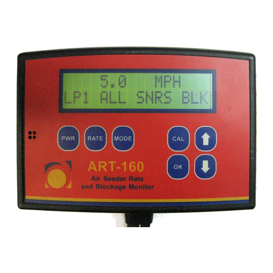
All sensors blocked (usually shown when not LP2 ALL SNRS BLK seeding) MAINTAIN POWER Monitor is saving settings before powering SAVE IN PROGRESS down. Do not disconnect from power during this process Page 34 ART 160 and ART 260 Rate & Blockage Monitors - Operator’s Manual... -
Page 35: Seed Sensor Sensitivity Values
Seeds/second Loop is off 1 seed 30 seconds 1 seed 20 seconds 1043 1 seed 10 seconds 2019 4400 4800 5300 5800 6400 7000 Product Sensitivity ART 160 and ART 260 Rate & Blockage Monitors - Operator’s Manual Page 35... -
Page 36: Conversion Factors
Newton-Meters 1.3568 Miles-Per-Hour Kilometers-Per-Hour 1.609 Pounds-Per-Acre Kilograms-Per-Hectare 1.1209 Acre-Per-Hour Hectare-Per-Hour 0.405 Feet-Per-Minute Meters-Per-Second 0.005 Feet-Per-Second Meters-Per-Second 0.305 Horsepower Kilowatt 0.746 27 in. of Water =1 psi Page 36 ART 160 and ART 260 Rate & Blockage Monitors - Operator’s Manual... -
Page 37: Default Calibration Values
Shaft 3 High alarm Test speed Shaft 4 targets Area 1 Shaft 4 Low alarm Area 2 Shaft 4 High alarm Distance Units Audible alarm Hours Mins ART 160 and ART 260 Rate & Blockage Monitors - Operator’s Manual Page 37... -
Page 38: Sensor Breakout Connector Pin-Out
Quick Start Guide Sensor Breakout Connector Pin-out Pin # Color Grey Shield Black Ground Yellow Seed Sensors (do not use) Green Seed Sensors (do not use) Loop 1 – Sensor Channel 4 Brown Loop 2 – Sensor Channel 7 Loop 1 – Sensor Channel 5 Loop 2 –... -
Page 39: Parts List
ART Loop Terminator Magnet Collar Kit for 1” Shaft (2 magnets) 9KMK102 Magnet Collar Kit for 1” Shaft (4 magnets) 9KMK104 850033006 RAM Mount M5 Hex Screws 450014004 ART 160 and ART 260 Rate & Blockage Monitors - Operator’s Manual Page 39... -
Page 40: Menu Navigation Flow Chart
Quick Start Guide Menu Navigation Flow Chart MODE MODE Only appears if MODE speed sensor is RATE selected Pressing RATE switches loops. MODE MODE Only appears if Rate Units are in LBS/ACRE Only appears if speed sensor is selected RATE MODE Only appears if work switch is selected Page 40... -
Page 41: Notes
Flow Chart Notes ART 160 and ART 260 Rate & Blockage Monitors - Operator’s Manual Page 41... -
Page 42: Warranty
3. If replacement parts are sent by Agtron Enterprises Inc., the customer will have 30 days to return the original defective product. A credit card is required and after 30 days the customer will be charged if the defective product is not received by Agtron Enterprises Inc. - Page 43 Warranty Page 42 ART 160 and ART 260 Rate & Blockage Monitors - Operator’s Manual...
Need help?
Do you have a question about the ART 160 and is the answer not in the manual?
Questions and answers