Sign In
Upload
Manuals
Brands
Agilent Technologies Manuals
Measuring Instruments
U1401B
Agilent Technologies U1401B Manuals
Manuals and User Guides for Agilent Technologies U1401B. We have
3
Agilent Technologies U1401B manuals available for free PDF download: User's Manual And Service Manual, Installation Manual, Service Note
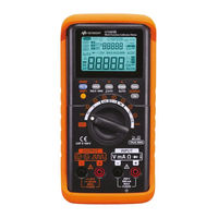
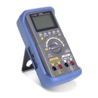
Agilent Technologies U1401B User's Manual And Service Manual (181 pages)
Handheld Multi-Function Calibrator/Meter
Brand:
Agilent Technologies
| Category:
Measuring Instruments
| Size: 7.73 MB
Table of Contents
Restricted Rights Legend
2
Safety Symbols
3
General Safety Information
4
Environmental Conditions
6
In this Guide
9
Table of Contents
11
1 Getting Started
22
Introducing the U1401B Handheld Multi-Function Calibrator/Meter
22
Standard Purchase Items
23
List of Accessories
24
Table 1-1 List of Accessories
24
Product Overview
25
Slide Switch
25
Table 1-2 Slide Switch Functions
25
Figure 1-1 the Slide Switch
25
The Front Panel at a Glance
27
Figure 1-2 the Front Panel
27
The Rotary Switch at a Glance
28
Figure 1-3 the Rotary Switch
28
The Keypad at a Glance
29
Table 1-3 Rotary Switch Positions and Their Corresponding Functions
29
Figure 1-4 Keypad Functions
29
Table 1-4 Keypad Functions
30
Figure 1-5 Keypad Shifted Functions
30
Table 1-5 Instructions Involving Shifted Functions
32
The Display at a Glance
33
Figure 1-6 Full Display
33
Table 1-6 Description of Display Annunciators
34
The Terminals at a Glance
37
Table 1-7 Description of Terminals
37
Figure 1-7 Terminals
37
Table 1-8 Overload Protection for the Input Terminals
38
The Rear Panel at a Glance
39
Figure 1-8 the Rear Panel
39
Display Selection with the Hz Key
40
Table 1-9 Measurement Functions and Corresponding Display Selection with the Hz Key
40
Display Selection with the DUAL Key
42
Table 1-10 Measurement Functions and Corresponding Display Selection with the DUAL Key
42
Remote Communication
43
Figure 1-9 IR-USB Cable
44
Figure 1-10 IR-USB Cable Connection
45
Figure 1-11 IR-USB Cable
45
2 Calibrator Output Operations
48
Enabling and Disabling the Output
48
Constant Voltage Operation
49
Constant Current Operation
50
Memory Generation
51
Autoscan Output
51
Table 2-1 Default Settings for the Autoscan Output
53
Figure 2-1 Selecting Autoscan Output Mode
54
Figure 2-2 Example of a Typical Autoscan Output
54
Autoramp Output
56
Figure 2-3 Defining the Autoscan Output
56
Table 2-2 Default Settings for the Autoramp Output
57
Figure 2-4 Selecting Autoramp Output Mode
58
Figure 2-5 Ramp Output
58
Figure 2-6 Defining the Autoramp Output
60
Square Wave Output
61
Table 2-3 Available Frequencies
61
Figure 2-7 Parameter Selection for Square Wave Output
63
3 Making Measurements
65
Measuring Voltage
66
Measuring DC Voltage
66
Figure 3-1 DC Voltage Measurement
67
Measuring AC Voltage
68
Figure 3-2 AC Voltage Measurement
68
Measuring Current
69
DC Ma Measurement
69
Figure 3-3 DC Current (Ma) Measurement
69
Percentage Scale of DC Ma Measurement
70
Measuring Temperature
71
Figure 3-4 Surface Temperature Measurement
73
Measuring Resistance and Testing Continuity
74
Table 3-1 Measurement Ranges for Audible Continuity
74
Figure 3-5 Resistance Measurement
75
Figure 3-6 Enabling and Disabling the Continuity Test
75
Alerts and Warning During Measurement
76
Overload Alert for Voltage Measurement
76
Math Operations
77
Dynamic Recording
77
Figure 3-7 Dynamic Recording Mode
79
Relative (Zero)
80
Figure 3-8 Relative (Zero) Mode
80
Triggering Operations
81
Data Hold (Manual Trigger)
81
Figure 3-9 Data Hold Mode
81
Refresh Hold (Auto Trigger)
82
Ms Peak Hold
83
Figure 3-10 1 Ms Peak Hold Mode
84
4 Changing the Default Settings
86
Entering the Setup Mode
86
Figure 4-1 Entering the Setup Mode
86
Available Setting Options
88
Table 4-1 Setup Options and Default Settings
88
Setting the Data Hold/Refresh Hold Mode
89
Figure 4-2 Setting the Data Hold or Refresh Hold Mode
90
Setting the Temperature Unit
91
Figure 4-3 Setting the Temperature Unit
92
Figure 4-4 Setting the Beeper Frequency
93
Setting the Beeper Frequency
93
Figure 4-5 Setting the Minimum Frequency
94
Setting the Minimum Measurable Frequency
94
Figure 4-6 Setting the Percentage Scale Readout
95
Setting the Percentage Scale Readout
95
Figure 4-7 Setting the Print Mode for Remote Control
96
Setting the Print Mode
96
Figure 4-8 Setting the Echo Mode for Remote Control
97
Setting the Echo Mode
97
Figure 4-9 Setting the Data Bit for Remote Control
98
Setting the Data Bit
98
Figure 4-10 Setting the Parity Check for Remote Control
99
Setting the Parity Check
99
Figure 4-11 Setting the Baud Rate for Remote Control
100
Setting the Baud Rate
100
Figure 4-12 Setting the Display Backlight Timer
101
Setting the Display Backlight Timer
101
Setting the Power Saving Mode
102
Figure 4-13 Setting the Auto Power-Off Mode
103
5 Application Examples
105
Source Mode for Ma Output
106
Figure 5-1. Testing a 4 Ma to 20 Ma Current Loop with the Source
107
Simulation Mode for Ma Output
108
Figure 5-2 Ma Output Simulation
109
Simulating a 2-Wire Transmitter on a Current Loop
110
Figure 5-3 Use the Yellow Test Lead to Perform the 2-Wire Transmitter Simulation
111
Measuring a Pressure Transducer
112
Table 5-1 Typical Pressure Range and Maximum Output Voltages of Millivolt Output Pressure Transducers
112
Figure 5-4 Pressure Transducer Measurement
113
Zener Diode Test
114
Figure 5-5 Zener Diode Test
115
Diode Test
116
Figure 5-6 Diode Test
117
Bipolar Junction Transistor (BJT) Test
118
Figure 5-7 TO-92 Transistor
118
Table 5-2 Base Terminal According to Probe Test
119
Table 5-3 Polarity and Terminals if Pin 3 Is the Base
119
Table 5-4 Polarities and Terminals if Pin 2 Is the Base
120
Table 5-5 Polarities and Terminals if Pin 1 Is the Base
120
Figure 5-8 TO-3 Transistor
121
Table 5-6 Polarity and Terminals if Pin 2 Is the Base
121
Determining Transistor H Fe
122
Figure 5-9 Determining Transistor H Fe
123
Junction Field-Effect Transistor (JFET) Switch Test
124
Figure 5-10 TO-92 JFET
124
Table 5-7 Gate Terminal According to Probe Test
125
Figure 5-11 N- Channel JFET
126
Figure 5-12 P- Channel JFET
127
Operational Amplifier Verification
128
Current-To-Voltage Converter
128
Figure 5-13 Current-To-Voltage Converter
129
Voltage-To-Current Converter
130
Integrator: Square Wave to Triangle Wave Conversion
131
Figure 5-14 Voltage-To-Current Converter
131
Figure 5-15 Square Wave to Triangular Wave Conversion
132
2-Wire Transmitter Verification
133
Figure 5-16 Verifying a Two-Wire Transmitter
134
Frequency Transmitter Verification
135
Figure 5-17 Verifying a Frequency Transmitter
136
6 Maintenance
137
Maintenance
138
General Maintenance
138
Battery Replacement
139
Figure 6-1 Battery Replacement
140
Recharging the Batteries
141
Fuse Replacement
142
Figure 6-2 Recharging the Batteries
142
Table 6-1 Fuse Specifications
143
Troubleshooting
144
Figure 6-3 Fuse Replacement
144
Table 6-2 Troubleshooting
145
7 Performance Tests and Calibration
148
Calibration Overview
148
Closed-Case Electronic Calibration
149
Agilent Technologies' Calibration Services
149
Calibration Interval
149
Other Recommendations for Calibration
150
Environmental Conditions
150
Warm up
150
Recommended Test Equipment
151
Table 7-1 Recommended Test Equipment
151
Performance Verification Tests
152
Self-Verification
152
Table 7-2 Functions that Can be Self-Verified
152
Input Performance Verification
153
Table 7-3 Input Performance Verification Tests
153
Output Performance Verification
157
Table 7-4 Output Performance Verification Tests
157
Adjustment Considerations
158
Adjustment Procedures
159
Input Calibration
159
Output Calibration
160
Output Calibration
164
General Specifications
164
8 Specifications
167
General Specifications
167
Input Specifications
167
DC Specifications
167
Measurement Category
167
Measurement Category Definitions
167
General Specifications
168
AC+DC Specifications
169
Measurement Category
170
Measurement Category Definitions
170
Table 8-1 DC MV/Voltage Specifications
171
Input Specifications
171
AC Specifications
172
Table 8-2 DC Current Specifications
172
Table 8-3 AC MV/Voltage Specifications
172
Table 8-4 AC Current Specifications
173
Table 8-5 AC+DC MV/Voltage Specifications
173
Temperature Specifications
174
Table 8-6 AC+DC Current Specifications
174
Table 8-7 Temperature Specifications
174
Frequency Specifications
175
Table 8-8 Frequency Specifications
175
Table 8-9. Frequency Sensitivity and Trigger Level Specifications for
175
Table 8-10 Duty Cycle Specifications
176
Table 8-11 Pulse Width Specifications
176
Table 8-12. Frequency Sensitivity Specifications for Current
176
Square Wave Output
176
Ms Peak Hold Specifications
177
Resistance Specifications
177
Table 8-13 Peak Hold Specifications
177
Table 8-14 Resistance Specifications
177
Diode Check and Audible Continuity Specifications
178
Table 8-15 Diode Check Specifications
178
Constant Voltage and Constant Current Outputs
179
Output Specifications
179
Table 8-16 Constant Voltage (CV) Output Specifications
179
Table 8-17 Constant Current (CC) Output Specifications
179
Table 8-18 Square Wave Output Specifications
180
Advertisement
Agilent Technologies U1401B Installation Manual (15 pages)
Brand:
Agilent Technologies
| Category:
Data Loggers
| Size: 0.25 MB
Table of Contents
Table of Contents
3
Introduction
5
System Requirements
6
Hardware Requirements
6
Software Requirements
7
Installing the Data Logger
8
A Shortcut to this Software will be Created on Your
8
Downloading the Application Software from the Web
8
Equipment Setup and Connection
10
Testing the Equipment Connections
11
Removing the Data Logger
13
Uninstalling from the Windows Start Menu
13
Uninstalling from the Windows Add/Remove Programs
14
Agilent Technologies U1401B Service Note (8 pages)
Handheld multi-function calibrator or meter
Brand:
Agilent Technologies
| Category:
Test Equipment
| Size: 0.46 MB
Advertisement
Advertisement
Related Products
Agilent Technologies U1461A
Agilent Technologies U1453A
Agilent Technologies U1213A
Agilent Technologies U1732C
Agilent Technologies U1733C
Agilent Technologies U1701A
Agilent Technologies U1701B
Agilent Technologies U1732A
Agilent Technologies U1271A
Agilent Technologies Acqiris U10 Series
Agilent Technologies Categories
Measuring Instruments
Laboratory Equipment
Test Equipment
Water Pump
Power Supply
More Agilent Technologies Manuals
Login
Sign In
OR
Sign in with Facebook
Sign in with Google
Upload manual
Upload from disk
Upload from URL