Sign In
Upload
Manuals
Brands
Agilent Technologies Manuals
Power Supply
6031A
Agilent Technologies 6031A Manuals
Manuals and User Guides for Agilent Technologies 6031A. We have
3
Agilent Technologies 6031A manuals available for free PDF download: Service Manual, Operating Manual
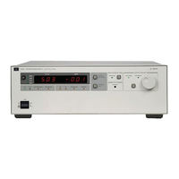
Agilent Technologies 6031A Operating Manual (134 pages)
Agilent Technologies OPERATING MANUAL 603xA FAMILY AUTORANGING SYSTEM DC POWER SUPPLIES
Brand:
Agilent Technologies
| Category:
Power Supply
| Size: 1.02 MB
Table of Contents
Operating Manual
1
Power Supplies
1
Safety Summary
3
Declaration of Conformity
5
Table of Contents
7
General Information
11
Description
11
Safety Considerations
12
Options
12
Accessories
12
Instrument & Manual Identification
13
GP-IB Cables & Interconnections
14
GP-IB Compatibility
14
Ordering Additional Manuals
14
Related Documents
15
Specifications
15
Installation
21
Introduction
21
Installation Introduction
21
Initial Inspection
21
Mechanical Check
21
Electrical Check
21
Preparation for Use
21
Location & Cooling
21
Outline Diagram
21
Bench Operation
22
Rack Mounting
22
Input Power Requirements
22
Power Connection
22
Line Voltage Option Conversion
24
AC Line Impedance Check
27
Repacking for Shipment
27
Rear Panel Screw Sizes and Part Numbers
27
Operating Instructions
29
Controls & Indicators
30
Output Range
30
Turn-On Checkout Procedure
33
Initial Setup & Interconnections
35
Connecting the Load
35
Overvoltage Protection
38
Adjustment
38
Reset
38
Foldback Protection
39
Remote Voltage Sensing
39
Mode Switches
40
GP-IB Connection
41
Monitor Signals
42
Protective Circuits
42
Overrange
42
Disabled
42
Overvoltage
42
Overtemperature
42
AC Line Voltage
42
Foldback
43
Error
43
Local Operation
43
Constant Voltage Operation
43
Constant Current Operation
44
Return to Local
44
GP-IB Operation
44
Interface Functions
44
Multiline Message Control
45
Service Request (SR1)
45
Serial Poll
45
Parallel Poll
45
Remote/Local
46
Device Clear
46
Device Trigger
46
GP-IB Address Selection
46
Power-On Service Request
47
INH-FLT/RLY LNK Operation
47
Initial Conditions
47
Programming Syntax
48
Numbers Sent to Supply
48
Numbers Returned to Controller
49
Separators for Data Sent to Power Supply
49
Terminators for Data Sent to Power Supply
54
Termination for Data to Controller
55
Voltage Setting
55
Current Setting
56
OVP Measurement
56
Soft Limits
57
Delay
57
Output On/Off
58
Foldback Protection
58
Reset
59
Hold & Trigger
59
Store & Recall
60
Status Register
60
Accumulated Status Register
61
Mask & Fault Registers
61
Service Request (SRQ)
62
Clear
63
Error
63
Test
63
Model Identification
65
Analog Programming
65
CV Output, Resistance Control
66
CV Output, Voltage Control
66
CC Output, Resistance Control
67
CC Output, Voltage Control
67
Multiple-Supply Operation
67
Auto-Parallel Operation
68
Setting Voltage & Current
69
Overvoltage Protection
69
Remote Sensing
69
Series Operation
69
FLT & Remote INH Connections
70
A 100 VAC Input Power Option 100
75
General Information
75
Description
75
Scope of Appendix A
75
Using Appendix A
75
Manual Changes
75
Section I Manual Changes
75
Section II Manual Changes
76
Section III Manual Changes
76
B Blank Front Panel Option 001
79
Introduction
79
Description
79
Turn-On Checkout Procedure
79
Overvoltage Protection Setting
81
Standard Commands for Programmable Instruments
83
About this Appendix
83
Reader Path
83
References
83
Introduction
84
Language Switching
84
Stand-Alone Connections
84
Linked Connections
85
Installation
85
Setting the Address
86
Primary Address
86
Secondary Address
86
Addressing over the Bus
86
Language Dictionary
87
Keywords
87
Parameters
87
Order of Presentation
87
COMMON Commands
87
Subsystem Commands
87
Current Subsystem
96
Initiate Subsystem
97
Measure Subsystem
97
Output Subsystem
97
Status Subsystem
99
Trigger Subsystem
103
Voltage Subsystem
103
Status Reporting
104
Questionable Status Group
104
Register Functions
104
Register Programming
105
Status Programming Examples
105
Operation Status Group
105
Register Functions
105
Status Programming Example
107
Standard Event Status Group
107
Register Functions
107
Status Programming Examples
108
Status Byte Register
108
The RQS Bit
108
The MSS Bit
108
Clearing the Status Byte Register
108
Service Request Enable Register
108
Register Functions
108
Register Programming
109
Status Programming Examples
109
Output Queue
109
SCPI Error Messages
109
System Errors
109
Device-Dependent Errors
110
Hardware Errors During Selftest
110
Hardware Errors During Operation
110
SCPI Command Summary
111
ARP/SCPI Commands
112
Programming the Agilent 603Xa Power Supplies Using BASIC
115
Introduction
115
I/O Path Names
115
Initialization
115
Voltage and Current Programming
115
Voltage and Current Readback
116
Output Inhibit/Enable
118
Power Supply Status
118
Present Status
118
Accumulated Status
119
Fault and Mask Registers
120
Serial Poll
121
Service Request
122
Delay Time
123
Programming Error Detection
123
Protection Features
125
Overvoltage
125
Foldback
125
Soft Programming Limits
125
Fault Indicator and Inhibit
125
Advanced Topics
126
Hold Mode
126
Machine States
126
Index
129
Agilent Sales and Support Office
133
Advertisement
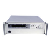
Agilent Technologies 6031A Service Manual (142 pages)
AUTORANGING SYSTEM DC POWER SUPPLY
Brand:
Agilent Technologies
| Category:
Power Supply
| Size: 5.85 MB
Table of Contents
Table of Contents
6
Introduction
10
Scope
10
Calibration and Verification
10
Troubleshooting
10
Principles of Operation
10
Replaceable Parts
10
Circuit Diagrams
10
Safety Considerations
10
Manual Revisions
11
Firmware Revisions
11
Calibration and Verification
12
Introduction
12
Test Equipment Required
12
Operation Verification Tests
12
Calibration Procedure
12
Initial Setup
15
Voltage Monitor Zero Calibration
16
Common Mode Calibration
16
Remote Readback Zero Calibration
16
Constant Voltage Full Scale Calibration
18
Voltage Monitor and Remote Readback Full Scale Calibration
18
Constant Voltage Zero Calibration
19
Current Monitor Zero Calibration
19
Constant Current Zero Calibration
19
Current Monitor Full Scale Calibration
20
Constant Current Full Scale Calibration
20
Power Limit Calibration
21
Resistance Programming Full Scale Calibration
22
Performance Tests
22
Measurement Techniques
22
Constant Voltage (CV) Tests
23
Constant Current (CC) Tests
29
Initialization Procedure
32
Troubleshooting
34
Introduction
34
Initial Troubleshooting Procedures
34
Electrostatic Protection
35
Repair and Replacement
35
A2 Control Board Removal
36
A4 FET Board Removal
36
A5 Diode Board Removal
37
A8 GPIB Board Removal
37
A3 Front-Panel Board Removal
37
A1 Main Board Removal
37
Overall Troubleshooting Procedure
38
GPIB Section Troubleshooting
38
Primary Interface Troubleshooting
41
Secondary Interface Troubleshooting
42
Voltage and Current DAC
42
Readback DAC Circuits
44
Readback Multiplexer (U20)
44
Signature Analysis
46
Primary SA
46
Front Panel SA
46
Secondary SA
47
Power Section Troubleshooting
52
Main Troubleshooting Setup
53
Troubleshooting No-Output Failures
54
Power Section Blocks
55
Troubleshooting AC-Turn-On Circuits
58
Troubleshooting DC-To-DC Converter
58
Troubleshooting Bias Supplies
59
Troubleshooting down Programmer
62
Troubleshooting CV Circuit
62
Troubleshooting CC Circuit
63
Troubleshooting OVP Circuit
63
Troubleshooting PWM & Clock
64
Principles of Operation
66
Introduction
66
GPIB Board
66
Primary Microprocessor
66
Address Switches
66
Eeprom
68
Isolation
68
Secondary Microprocessor
68
Digital-To-Analog Converters
68
Analog Multiplexer
68
Status Inputs
68
Front Panel Board
69
Address Latches and Decoders
69
Volts and Amps Output Ports and Displays
69
RPG and Latches
69
Front-Panel Switches and Input Port
69
Mode Indicators
71
OVP Adjust Control
71
Power Clear
71
Power Mesh and Control Board
71
Overview
71
Power Mesh
72
Control Board
74
Replaceable Parts
80
Introduction
80
Ordering Information
81
Component Location and Circuit Diagrams
102
L00 Vac Input Power Option 100
120
General Information
120
Description
120
Scope of Appendix A
120
Suggestions for Using Appendix A
120
Chapter 1 Manual Changes
120
Chapter 2 Manual Changes
120
Chapter 3 Manual Changes
124
Chapter 4 Manual Changes
124
Chapter 5 And 6 Manual Changes
124
Blank Front Panel Option 001
126
Introduction
126
Troubleshooting
126
Chapter 2 Manual Changes
126
Chapter 3 Manual Changes
127
Chapter 5 And 6 Manual Changes
127
Agilent Technologies 6031A Service Manual (134 pages)
AUTORANGING SYSTEM DC POWER SUPPLY
Brand:
Agilent Technologies
| Category:
Power Supply
| Size: 2.76 MB
Table of Contents
Limitation of Warranty
2
Exclusive Remedies
2
Safety Summary
3
Printing History
4
Table of Contents
5
Introduction
8
Scope
8
Calibration and Verification
8
Troubleshooting
8
Principles of Operation
8
Replaceable Parts
8
Circuit Diagrams
8
Safety Considerations
8
Manual Revisions
9
Firmware Revisions
9
Calibration and Verification
10
Introduction
10
Test Equipment Required
10
Operation Verification Tests
10
Calibration Procedure
10
Initial Setup
13
Voltage Monitor Zero Calibration
14
Common Mode Calibration
14
Remote Readback Zero Calibration
14
Constant Voltage Full Scale Calibration
16
Voltage Monitor and Remote Readback Full Scale Calibration
16
Constant Voltage Zero Calibration
17
Current Monitor Zero Calibration
17
Constant Current Zero Calibration
17
Current Monitor Full Scale Calibration
18
Constant Current Full Scale Calibration
18
Power Limit Calibration
19
Resistance Programming Full Scale Calibration
20
Performance Tests
20
Measurement Techniques
20
Constant Voltage (CV) Tests
21
Constant Current (CC) Tests
27
Initialization Procedure
30
Troubleshooting
31
Introduction
31
Initial Troubleshooting Procedures
31
Electrostatic Protection
32
Repair and Replacement
32
A2 Control Board Removal
33
A4 FET Board Removal
33
A5 Diode Board Removal
34
A8 GPIB Board Removal
34
A3 Front-Panel Board Removal
34
A1 Main Board Removal
34
Overall Troubleshooting Procedure
35
GPIB Section Troubleshooting
35
Primary Interface Troubleshooting
38
Secondary Interface Troubleshooting
39
Voltage and Current DAC
39
Readback DAC Circuits
41
Readback Multiplexer (U20)
41
Signature Analysis
43
Primary SA
43
Front Panel SA
43
Secondary SA
44
Power Section Troubleshooting
49
Main Troubleshooting Setup
50
Troubleshooting No-Output Failures
51
Power Section Blocks
52
Troubleshooting AC-Turn-On Circuits
55
Troubleshooting DC-To-DC Converter
55
Troubleshooting Bias Supplies
56
Troubleshooting down Programmer
59
Troubleshooting CV Circuit
59
Troubleshooting CC Circuit
60
Troubleshooting OVP Circuit
60
Troubleshooting PWM & Clock
61
Principles of Operation
63
Introduction
63
GPIB Board
63
Primary Microprocessor
63
Address Switches
63
Eeprom
65
Isolation
65
Secondary Microprocessor
65
Digital-To-Analog Converters
65
Analog Multiplexer
65
Status Inputs
65
Front Panel Board
66
Address Latches and Decoders
66
Volts and Amps Output Ports and Displays
66
RPG and Latches
66
Front-Panel Switches and Input Port
66
Mode Indicators
68
OVP Adjust Control
68
Power Clear
68
Power Mesh and Control Board
68
Overview
68
Power Mesh
69
Control Board
71
Replaceable Parts
76
Introduction
76
Ordering Information
77
Component Location and Circuit Diagrams
98
L00 Vac Input Power Option 100
116
General Information
116
Description
116
Scope of Appendix A
116
Suggestions for Using Appendix A
116
Chapter 1 Manual Changes
116
Chapter 2 Manual Changes
116
Chapter 3 Manual Changes
120
Chapter 4 Manual Changes
120
Chapter 5 And 6 Manual Changes
120
Blank Front Panel Option 001
121
Introduction
121
Troubleshooting
121
Chapter 2 Manual Changes
121
Chapter 3 Manual Changes
122
Chapter 5 And 6 Manual Changes
122
Advertisement
Advertisement
Related Products
Agilent Technologies 6032A
Agilent Technologies 6033A
Agilent Technologies 6035A
Agilent Technologies 603xA FAMILY
Agilent Technologies 6038A 6010A
Agilent Technologies 6030A
Agilent Technologies 6038A
Agilent Technologies 6010A
Agilent Technologies 6011A
Agilent Technologies 6015A
Agilent Technologies Categories
Measuring Instruments
Laboratory Equipment
Test Equipment
Water Pump
Power Supply
More Agilent Technologies Manuals
Login
Sign In
OR
Sign in with Facebook
Sign in with Google
Upload manual
Upload from disk
Upload from URL