Sign In
Upload
Manuals
Brands
Agilent Technologies Manuals
Power Supply
6030A
Agilent Technologies 6030A Manuals
Manuals and User Guides for Agilent Technologies 6030A. We have
2
Agilent Technologies 6030A manuals available for free PDF download: Service Manual
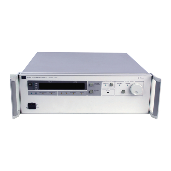
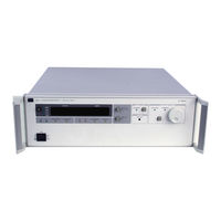
Agilent Technologies 6030A Service Manual (142 pages)
AUTORANGING SYSTEM DC POWER SUPPLY
Brand:
Agilent Technologies
| Category:
Power Supply
| Size: 5.85 MB
Table of Contents
Table of Contents
6
Introduction
10
Scope
10
Calibration and Verification
10
Troubleshooting
10
Principles of Operation
10
Replaceable Parts
10
Circuit Diagrams
10
Safety Considerations
10
Manual Revisions
11
Firmware Revisions
11
Calibration and Verification
12
Introduction
12
Test Equipment Required
12
Operation Verification Tests
12
Calibration Procedure
12
Initial Setup
15
Voltage Monitor Zero Calibration
16
Common Mode Calibration
16
Remote Readback Zero Calibration
16
Constant Voltage Full Scale Calibration
18
Voltage Monitor and Remote Readback Full Scale Calibration
18
Constant Voltage Zero Calibration
19
Current Monitor Zero Calibration
19
Constant Current Zero Calibration
19
Current Monitor Full Scale Calibration
20
Constant Current Full Scale Calibration
20
Power Limit Calibration
21
Resistance Programming Full Scale Calibration
22
Performance Tests
22
Measurement Techniques
22
Constant Voltage (CV) Tests
23
Constant Current (CC) Tests
29
Initialization Procedure
32
Troubleshooting
34
Introduction
34
Initial Troubleshooting Procedures
34
Electrostatic Protection
35
Repair and Replacement
35
A2 Control Board Removal
36
A4 FET Board Removal
36
A5 Diode Board Removal
37
A8 GPIB Board Removal
37
A3 Front-Panel Board Removal
37
A1 Main Board Removal
37
Overall Troubleshooting Procedure
38
GPIB Section Troubleshooting
38
Primary Interface Troubleshooting
41
Secondary Interface Troubleshooting
42
Voltage and Current DAC
42
Readback DAC Circuits
44
Readback Multiplexer (U20)
44
Signature Analysis
46
Primary SA
46
Front Panel SA
46
Secondary SA
47
Power Section Troubleshooting
52
Main Troubleshooting Setup
53
Troubleshooting No-Output Failures
54
Power Section Blocks
55
Troubleshooting AC-Turn-On Circuits
58
Troubleshooting DC-To-DC Converter
58
Troubleshooting Bias Supplies
59
Troubleshooting down Programmer
62
Troubleshooting CV Circuit
62
Troubleshooting CC Circuit
63
Troubleshooting OVP Circuit
63
Troubleshooting PWM & Clock
64
Principles of Operation
66
Introduction
66
GPIB Board
66
Primary Microprocessor
66
Address Switches
66
Eeprom
68
Isolation
68
Secondary Microprocessor
68
Digital-To-Analog Converters
68
Analog Multiplexer
68
Status Inputs
68
Front Panel Board
69
Address Latches and Decoders
69
Volts and Amps Output Ports and Displays
69
RPG and Latches
69
Front-Panel Switches and Input Port
69
Mode Indicators
71
OVP Adjust Control
71
Power Clear
71
Power Mesh and Control Board
71
Overview
71
Power Mesh
72
Control Board
74
Replaceable Parts
80
Introduction
80
Ordering Information
81
Component Location and Circuit Diagrams
102
L00 Vac Input Power Option 100
120
General Information
120
Description
120
Scope of Appendix A
120
Suggestions for Using Appendix A
120
Chapter 1 Manual Changes
120
Chapter 2 Manual Changes
120
Chapter 3 Manual Changes
124
Chapter 4 Manual Changes
124
Chapter 5 And 6 Manual Changes
124
Blank Front Panel Option 001
126
Introduction
126
Troubleshooting
126
Chapter 2 Manual Changes
126
Chapter 3 Manual Changes
127
Chapter 5 And 6 Manual Changes
127
Advertisement
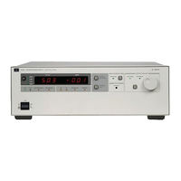
Agilent Technologies 6030A Service Manual (134 pages)
AUTORANGING SYSTEM DC POWER SUPPLY
Brand:
Agilent Technologies
| Category:
Power Supply
| Size: 2.76 MB
Table of Contents
Limitation of Warranty
2
Exclusive Remedies
2
Safety Summary
3
Printing History
4
Table of Contents
5
Introduction
8
Scope
8
Calibration and Verification
8
Troubleshooting
8
Principles of Operation
8
Replaceable Parts
8
Circuit Diagrams
8
Safety Considerations
8
Manual Revisions
9
Firmware Revisions
9
Calibration and Verification
10
Introduction
10
Test Equipment Required
10
Operation Verification Tests
10
Calibration Procedure
10
Initial Setup
13
Voltage Monitor Zero Calibration
14
Common Mode Calibration
14
Remote Readback Zero Calibration
14
Constant Voltage Full Scale Calibration
16
Voltage Monitor and Remote Readback Full Scale Calibration
16
Constant Voltage Zero Calibration
17
Current Monitor Zero Calibration
17
Constant Current Zero Calibration
17
Current Monitor Full Scale Calibration
18
Constant Current Full Scale Calibration
18
Power Limit Calibration
19
Resistance Programming Full Scale Calibration
20
Performance Tests
20
Measurement Techniques
20
Constant Voltage (CV) Tests
21
Constant Current (CC) Tests
27
Initialization Procedure
30
Troubleshooting
31
Introduction
31
Initial Troubleshooting Procedures
31
Electrostatic Protection
32
Repair and Replacement
32
A2 Control Board Removal
33
A4 FET Board Removal
33
A5 Diode Board Removal
34
A8 GPIB Board Removal
34
A3 Front-Panel Board Removal
34
A1 Main Board Removal
34
Overall Troubleshooting Procedure
35
GPIB Section Troubleshooting
35
Primary Interface Troubleshooting
38
Secondary Interface Troubleshooting
39
Voltage and Current DAC
39
Readback DAC Circuits
41
Readback Multiplexer (U20)
41
Signature Analysis
43
Primary SA
43
Front Panel SA
43
Secondary SA
44
Power Section Troubleshooting
49
Main Troubleshooting Setup
50
Troubleshooting No-Output Failures
51
Power Section Blocks
52
Troubleshooting AC-Turn-On Circuits
55
Troubleshooting DC-To-DC Converter
55
Troubleshooting Bias Supplies
56
Troubleshooting down Programmer
59
Troubleshooting CV Circuit
59
Troubleshooting CC Circuit
60
Troubleshooting OVP Circuit
60
Troubleshooting PWM & Clock
61
Principles of Operation
63
Introduction
63
GPIB Board
63
Primary Microprocessor
63
Address Switches
63
Eeprom
65
Isolation
65
Secondary Microprocessor
65
Digital-To-Analog Converters
65
Analog Multiplexer
65
Status Inputs
65
Front Panel Board
66
Address Latches and Decoders
66
Volts and Amps Output Ports and Displays
66
RPG and Latches
66
Front-Panel Switches and Input Port
66
Mode Indicators
68
OVP Adjust Control
68
Power Clear
68
Power Mesh and Control Board
68
Overview
68
Power Mesh
69
Control Board
71
Replaceable Parts
76
Introduction
76
Ordering Information
77
Component Location and Circuit Diagrams
98
L00 Vac Input Power Option 100
116
General Information
116
Description
116
Scope of Appendix A
116
Suggestions for Using Appendix A
116
Chapter 1 Manual Changes
116
Chapter 2 Manual Changes
116
Chapter 3 Manual Changes
120
Chapter 4 Manual Changes
120
Chapter 5 And 6 Manual Changes
120
Blank Front Panel Option 001
121
Introduction
121
Troubleshooting
121
Chapter 2 Manual Changes
121
Chapter 3 Manual Changes
122
Chapter 5 And 6 Manual Changes
122
Advertisement
Related Products
Agilent Technologies 6031A
Agilent Technologies 6032A
Agilent Technologies 6033A
Agilent Technologies 6035A
Agilent Technologies 603xA FAMILY
Agilent Technologies 6038A 6010A
Agilent Technologies 6038A
Agilent Technologies 6010A
Agilent Technologies 6011A
Agilent Technologies 6015A
Agilent Technologies Categories
Measuring Instruments
Laboratory Equipment
Test Equipment
Water Pump
Power Supply
More Agilent Technologies Manuals
Login
Sign In
OR
Sign in with Facebook
Sign in with Google
Upload manual
Upload from disk
Upload from URL