Sign In
Upload
Manuals
Brands
Afag Manuals
Controller
SE-Power FS
User Manuals: Afag SE-Power FS Servo Controller
Manuals and User Guides for Afag SE-Power FS Servo Controller. We have
2
Afag SE-Power FS Servo Controller manuals available for free PDF download: Manual, Operating Instruction
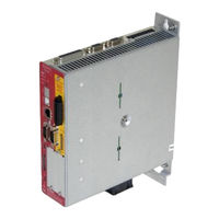
Afag SE-Power FS Manual (60 pages)
Servo Controller
Brand:
Afag
| Category:
Controller
| Size: 1 MB
Table of Contents
Table of Contents
2
1 General
8
Documentation
8
2 Used Symbols
10
3 Safety and Requirements for Product Use
11
Safety
11
General Safety Information
11
Intended Use
12
Possible Incorrect Application
12
Achievable Safety Level, Safety Function According to en ISO 13849-1 / en 61800-5-2
13
Requirements for Product Use
13
Technical Requirements
13
Qualification of the Specialist Personnel (Requirements for Personnel)
14
Diagnostic Coverage (DC)
14
Range of Applications and Certification
14
4 Product Description SE-Power Safety Module STO
15
Product Overview
15
Purpose
15
Supported Devices
15
Table 1: Overview Safety-Activation-Modules for the SE-Power FS
15
Control Sections and Connections
16
Figure 1: Operator Panel and Connections SE-Power FS Safety Module STO
16
Function and Application
17
Description of the Safety Function STO
18
Figure 2: "Safe Torque Off" - Operating Principle for the SE-Power FS
18
Overview of Interface [X40]
19
Control Ports STO-A, 0V-A / STO-B, 0V-B [X40]
20
Table 2: Function of the Module Connections
20
Feedback Contact C1, C2 [X40]
21
Auxiliary Supply 24V, 0V [X40]
22
Status Display
22
DIP Switch
22
Functionalities in the Basic SE-Power FS
22
Table 3: Detection and Response Times of the Driver Supply Voltage
24
Time Behaviour
25
Basic Time Behaviour STO
25
Figure 3: Basic Time Behaviour When Activating and Deactivating the Safety Function STO
25
Table 4: Time Data Concerning Figure 3
25
Time Behaviour for Activating STO During Operation with Restart
26
Figure 4: Time Behaviour When Activating the Safety Function STO with Restart
26
Table 5: Time Data Concerning Figure 4
27
Time Behaviour for Activating SS1 During Operation with Restart
28
Figure 5: Time Behaviour When Activating the Safety Function SS1 (External Switching) with Restart
28
Table 6: Time Data Concerning Figure 5
29
5 Assembly and Installation
30
Mounting / Dismounting
30
Mounting the Safety Module
31
Figure 6: Mounting / Dismounting
31
Safety Instructions
32
Table 7: Pin Assignment [X40]
33
Minimum Wiring for Commissioning [X40]
33
Figure 7: Connection of the SE-Power FS Safety Modul STO, Example of Single-Phase Servo Drive SE-Power FS
34
Typical Circuits
34
Delays and Safe Torque off (SS1, „Safe Stop 1")
36
Figure 8: Typical Circuit "Decelerate and Safe Torque Off" (SS1, "Safe Stop 1"), Example Single-Phase Servo Drive SE-Power FS
36
Commissioning
38
Parameterisation with the Afag SE-Commander
39
Figure 9: Indication of the Type of Safety Module and Extended Status Window
40
Type Indication Servo Drive and Safety Module
40
Figure 10: Quick-Access Toolbar with the Button "Safety
41
Status Indication of the State Machine
41
Figure 11: Window "Safety Module" STO (Left) and MOV (Right)
42
Table 8: Meaning of the Leds for the Status Display in the Window "Safety Module
43
Function Test, Validation
44
Table 10: Questions for Validation in Accordance with en ISO 13849-1 and 2 (Example)
45
Operation
46
Table 11: LED- Display on the Safety Module
47
Table 12: Seven Segment Display on the Servo Drive
47
Diagnostics and Troubleshooting
47
Table 13: Error Messages Relating to the Safety Module
48
Conversion and Module Replacement
49
Replacing the Previous Series SE-Power with the SE-Power FS
50
Information for Configuration
51
Table 14: Technical Data: Safety Indicators
52
Table 15: Technical Data: Safety Specifications
52
Technical Appendix
52
Table 16: Technical Data: Mechanical
53
Table 17: Technical Data: Certifications
53
Operating and Environmental Conditions
54
Table 18: Technical Data: Transport
54
Table 19: Technical Data: Storage
54
Table 20: Technical Data: Ambient Conditions
54
Table 21: Technical Data: Electrical for Ports STO-A and STO-B
55
Table 22: Typical Switch-Off Time and Minimum Tolerance Time for Test Pulse (OSSD Signals)
55
Table 23: Technical Data: Electrical Data of the Feedback Contact C1/C2
56
Table 24: Technical Data: Electrical Data of the Auxiliary Supply Output
56
Table 25: Technical Data: Electrical Isolation [X40]
56
Table 26: Technical Data: Cabling to [X40]
57
Glossary
58
Table 27: Terms and Abbreviations
58
Advertisement
Afag SE-Power FS Operating Instruction (50 pages)
Brand:
Afag
| Category:
Industrial Equipment
| Size: 1 MB
Table of Contents
Table of Contents
2
General
6
Documentation
6
Safety Notes for Electrical Drives and Controllers
8
Used Symbols
8
General Notes
9
Danger Resulting from Misuse
11
Safety Notes
12
General Safety Notes
12
Safety Notes for Assembly and Maintenance
14
Protection against Contact with Electrical Parts
15
Protection against Electrical Shock by Means of Protective Extra-Low Voltage (PELV)
16
Protection against Dangerous Movements
17
Protection against Contact with Hot Parts
17
Protection During Handling and Assembly
18
Technical Data
19
Table 1: Technical Data: Ambient Conditions and Qualification
19
Table 2: Technical Data: Dimensions and Weight
19
Table 3: Technical Data: Cable Specifications
19
Operating and Display Elements
20
Supply [X9]
20
Table 4: Technical Data: Motor Temperature Monitoring
20
Table 5: Display Elements and RESET Button
20
Table 6: Technical Data: Performance Data [X9]
20
Motor Connection [X6]
21
I/O Interface [X1]
21
Table 7: Technical Data: Motor Connection Data [X6]
21
Table 8: Technical Data: Digital Inputs and Outputs [X1]
21
Functional Safety Technology
22
Function and Application
22
Table 9: Overview Safety Activation Module for the SE-Power FS
22
Table 10: Fieldbus Specific Assignment of the R DIP Switches
22
Table 11: Pin Assignment [X40]
23
Mechanical Installation
24
Important Notes
24
Figure 1: Servo Positioning Controller SE-Power FS 1Kva: Installation Space
25
Figure 2: Servo Positioning Controller SE-Power FS 3Kva and 6Kva: Installation Space
26
View of the Device
27
Figure 3: Servo Positioning Controller SE-Power FS 1Kva: Front View
27
Figure 4: Servo Positioning Controller SE-Power FS 3Kva and 6Kva: Front View
28
Figure 5: Servo Positioning Controller SE-Power FS 1Kva: Top View
29
Figure 6: Servo Positioning Controller SE-Power FS 1Kva: Bottom View
29
Figure 7: Servo Positioning Controller SE-Power FS 3Kva and 6Kva: Top View
30
Figure 8: Servo Positioning Controller SE-Power FS 3Kva and 6Kva: Bottom View
30
Mounting
31
Figure 9: Servo Positioning Controller SE-Power FS 1Kva: Mounting Plate
31
Figure 10: Servo Positioning Controller SE-Power FS 3Kva and 6Kva: Mounting Plate
32
Electrical Installation
33
Connector Configuration (SE-Power FS 1Kva)
33
Figure 11: SE-Power FS 1Kva Connection to the Power Supply and Motor
33
Connector Configuration (SE-Power FS 3Kva and 6Kva)
34
Figure 12: SE-Power FS 3Kva and 6Kva 1Kva Connection to the Power Supply and Motor
34
Connection: Power Supply [X9]
36
Figure 13: Supply [X9] SE-Power FS 1Kva
36
Table 12: Pin Assignment [X9] SE-Power FS 1Kva
36
Figure 14: Supply [X9] SE-Power FS 3Kva and 6Kva
37
Table 13: Pin Assignment [X9] SE-Power FS 3Kva und 6Kva
37
Connection: Motor [X6]
38
Table 14: Pin Assignment [X6] SE-Power FS 1Kva
38
Table 15: Pin Assignment [X6] SE-Power FS 3Kva und 6Kva
38
Pin Assignment [X1]
39
Table 16: Pin Assignment: I/O Communication [X1]
39
Connection: RS232/COM [X5]
40
Cable Type and Design [X5]
40
Figure 15: Pin Assignment RS232-Null Modem Cable [X5]
40
Table 17: Pin Assignment RS232 Interface [X5]
40
Connection: USB [X19]
41
Cable Type and Design [X19]
41
Figure 16: Pin Assignment: USB Interface [X19], Front View
41
Table 18: Pin Assignment: USB Interface [X19]
41
EMC Compliant Cabling
42
ESD Protection
43
Initial Operation
44
General Notes on Connection
44
Figure 17: Servo Positioning Controller: Labelling Order
44
Connecting the Motor
45
Connecting the Servo Positioning Controller to the Power Supply
45
Connecting the PC (USB Interface)
45
Connecting the PC (RS232 Interface)
45
Checking Operability
46
Scaling Check
46
Switch on Controller Enable
46
Table 19: Dependence Power Stage and Controller Enable
46
Programming (over Digital I/O's)
47
Advertisement
Related Products
Afag Electric Slide Series
Afag SE-24
Afag SE20
Afag SE30
Afag SA-3 Series
Afag SA-3-050
Afag SA-3-100
Afag SA-3-100-FL
Afag SA-3-150-FL
Afag SREH-50-IOL
Afag Categories
Industrial Equipment
Control Unit
Controller
Wire Feeders
DC Drives
More Afag Manuals
Login
Sign In
OR
Sign in with Facebook
Sign in with Google
Upload manual
Upload from disk
Upload from URL