Sign In
Upload
Manuals
Brands
Aerotech Manuals
Industrial Equipment
PRO560LM Series
Aerotech PRO560LM Series Manuals
Manuals and User Guides for Aerotech PRO560LM Series. We have
2
Aerotech PRO560LM Series manuals available for free PDF download: Hardware Manual
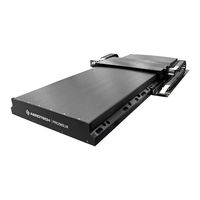
Aerotech PRO560LM Series Hardware Manual (56 pages)
Mechanical Bearing, Direct-Drive Linear Stage
Brand:
Aerotech
| Category:
Industrial Equipment
| Size: 1.82 MB
Table of Contents
PRO560LM Mechanical Bearing, Direct-Drive Linear Stage
1
Table of Contents
3
List of Figures
4
List of Tables
5
EU Declaration of Incorporation
6
UKCA Declaration of Incorporation
7
Safety Procedures and Warnings
8
Installation and Operation
9
Electrical Warnings
10
Motor-Related Warnings
11
Pinch Points
12
Magnetic Hazards
13
Handling and Storage
14
Storage
15
Chapter 1: Overview
17
Table 1-1: Model Numbers and Ordering Options
17
Environmental Specifications
19
Table 1-2: Environmental Specifications
19
Accuracy and Temperature Effects
20
Basic Specifications
21
Table 1-3: PRO560LM Series Specifications (-0400 to -1000)
21
Table 1-4: PRO560LM Series Specifications (-0800 to -1500)
22
Vacuum Operation
23
Vacuum Guidelines
23
Chapter 2: Installation
25
Dimensions
25
Figure 2-1: PRO560LM Dimensions
25
Figure 2-2: PRO560LM Tabletop Dimensions (-TT2/-TT3 Option)
26
Securing the Stage to the Mounting Surface
27
Table 2-1: Stage Mounting Surface Flatness Requirement
27
Table 2-2: Stage to Mounting Surface Hardware
27
Attaching the Payload to the Stage
28
Table 2-3: Payload Mounting Surface Flatness Requirement
28
Figure 2-3: Stage Orientations
29
Figure 2-4: Cantilevered Load Capability
29
Speed Capability
30
Chapter 3: Electrical Installation
31
Motor and Feedback Connectors
32
Figure 3-1: Ground Connection Points for the -CMS0 Option
32
Table 3-1: Motor Connector Pinout
33
Table 3-2: General Motor Connector Pinout (for Z or T Axes)
33
Table 3-3: Mating Connector Part Numbers for the Motor Connector
33
Table 3-4: Feedback Connector Pinout
34
Table 3-5: Mating Connector Part Numbers for the Brushless Motor Feedback Connector
34
Table 3-6: Feedback Connector Pinout (-E3 Option)
35
Table 3-7: Mating Connector Part Numbers for the Encoder Connector
35
Table 3-8: General Feedback Connector Pinout (for Z or T Axes)
36
Table 3-9: Mating Connector Part Numbers for the Encoder Connector
36
Motor and Feedback Wiring
37
Figure 3-2: Motor and Feedback Wiring
37
Figure 3-3: Motor and Feedback Wiring for a Typical Vertical or Rotary Axis Stage
38
Motor and Feedback Specifications
39
Table 3-10: Hall-Effect Sensor Specifications
39
Table 3-11: Thermistor Specifications
39
Table 3-12: Encoder Specifications
39
Table 3-13: Linear Encoder Resolution Specifications
39
Table 3-14: Limit Switch Specifications
40
Table 3-15: PRO560LM Motor Specifications (BLMH-262-A)
40
Limits, Marker, and Machine Direction
41
Figure 3-4: Machine Direction
41
Motor and Feedback Phasing
42
Figure 3-5: Hall Phasing Diagram
42
Figure 3-6: Encoder Phasing Reference Diagram (Standard/Square Wave)
43
Figure 3-7: Digital Encoder Phasing Reference Diagram (Sine Wave)
43
Chapter 4: Maintenance
45
Service and Inspection Schedule
45
Cleaning and Lubrication
46
Figure 4-1: Hardcover Rear End Plate Removal
48
Figure 4-2: Hardcover Screw Removal
48
Figure 4-3: Hardcover Removal
49
Troubleshooting
50
Appendix A: Warranty and Field Service
51
Appendix B: Revision History
53
Index
55
Vibration
56
Warnings
56
Advertisement
Aerotech PRO560LM Series Hardware Manual (52 pages)
Brand:
Aerotech
| Category:
Industrial Equipment
| Size: 5.9 MB
Table of Contents
PRO560LM Hardware Manual
1
Table of Contents
3
List of Figures
4
List of Tables
5
Safety Procedures and Warnings
7
EU Declaration of Incorporation
9
Chapter 1: Overview
11
Table 1-1: Model Numbers and Ordering Options
11
Environmental Specifications
13
Accuracy and Temperature Effects
13
Table 1-2: Environmental Specifications
13
Basic Specifications
14
Table 1-3: PRO560LM Series Specifications (-0400 to -1000)
14
Table 1-4: PRO560LM Series Specifications (-0800 to -1500)
15
Vacuum Operation
16
Chapter 2: Mechanical Specifications and Installation
17
Unpacking and Handling the Stage
17
Figure 2-1: Shipping Brackets Used on Single Axis Stages or Upper Axes of XY Systems
18
Figure 2-2: PRO560LM Series Stage with Lifting Features
19
Dimensions
20
Figure 2-3: PRO560LM Dimensions
20
Figure 2-4: PRO560LM Accessory Tabletop Dimensions (-TT3, -TT6 Options)
21
Figure 2-5: Dimensions for Stages Without a Cable Management System (-CMS0 Option)
22
Securing the Stage to the Mounting Surface
23
Table 2-1: Stage Mounting Surface Flatness Requirement
23
Table 2-2: Stage to Mounting Surface Hardware
23
Attaching the Payload to the Stage
24
Speed Capability
25
Figure 2-6: Cantilevered Load Capability of PRO560LM Series Stages
25
Figure 2-7: Stage Orientations
25
Chapter 3: Electrical Specifications and Installation
27
Motor and Feedback Connectors
28
Figure 3-1: Ground Connection Points for the -CMS0 Option
28
Table 3-1: Motor Connector Pinout
29
Table 3-2: Mating Connector Part Numbers for the Motor Connector
29
Table 3-3: Feedback Connector Pinout (-E1 and -E2 Options)
30
Table 3-4: Mating Connector Part Numbers for the Feedback Connector
30
Table 3-5: Feedback Connector Pinout (-E3 Option)
31
Table 3-6: Mating Connector Part Numbers for the Feedback Connector
31
Table 3-7: General Motor Connector Pinout (for Z or T Axes)
32
Table 3-8: Mating Connector Part Numbers for the Motor Connector
32
Table 3-9: General Feedback Connector Pinout (for Z or T Axes)
33
Table 3-10: Mating Connector Part Numbers for the Feedback Connector
33
Motor and Feedback Wiring
34
Figure 3-2: Motor and Feedback Wiring
34
Figure 3-3: Motor and Feedback Wiring for a Typical Vertical or Rotary Axis Stage
35
Motor and Feedback Specifications
36
Table 3-11: Feedback Specifications
36
Table 3-12: PRO560LM Linear Motor Specifications (Dual BLMH-262-A Motors)
37
Table 3-13: Encoder Specifications
37
Limits, Marker, and Machine Direction
38
Figure 3-4: Machine Direction
38
Motor and Feedback Phasing
39
Figure 3-5: Hall Phasing
39
Figure 3-6: Analog Encoder Phasing Reference Diagram (-E1 Incremental Encoder)
40
Figure 3-7: Encoder Phasing Reference Diagram (-E2 Incremental Encoder)
40
Chapter 4: Maintenance
41
Service and Inspection Schedule
41
Cleaning and Lubrication
42
Figure 4-1: Endplate Cover Removal (Step 2)
44
Figure 4-2: Hardcover Screw Removal (Step 3)
44
Figure 4-3: Hardcover Removal (Step 3)
45
Troubleshooting
46
Appendix A: Warranty and Field Service
47
Appendix B: Technical Changes
49
Index
51
Advertisement
Related Products
Aerotech PRO560LM-0300
Aerotech PRO560LM-0400
Aerotech PRO560LM-0500
Aerotech PRO560LM-0600
Aerotech PRO560LM-0800
Aerotech PRO560LM-1000
Aerotech PRO560LM-1200
Aerotech PRO560LM-1500
Aerotech PRO115SL-300
Aerotech PRO165SL Series
Aerotech Categories
Industrial Equipment
DC Drives
Controller
Engine
Valve Positioners
More Aerotech Manuals
Login
Sign In
OR
Sign in with Facebook
Sign in with Google
Upload manual
Upload from disk
Upload from URL