Sign In
Upload
Manuals
Brands
Aerotech Manuals
DC Drives
Automation1 XR3 Series
Aerotech Automation1 XR3 Series Manuals
Manuals and User Guides for Aerotech Automation1 XR3 Series. We have
2
Aerotech Automation1 XR3 Series manuals available for free PDF download: Hardware Manual
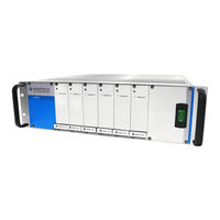
Aerotech Automation1 XR3 Series Hardware Manual (112 pages)
Drive Racks
Brand:
Aerotech
| Category:
DC Drives
| Size: 14 MB
Table of Contents
Automation1 Ixr3 and XR3 Drive Racks
1
Table of Contents
3
List of Figures
5
List of Tables
7
EU Declaration of Conformity
9
Agency Approvals
10
Safety Procedures and Warnings
11
Handling and Storage
13
Installation Overview
14
Chapter 1: Ixr3/Xr3 Overview
15
Figure 1-1: Ixr3 Connection Overview
15
Figure 1-2: XR3 Connection Overview
16
Table 1-1: Feature Summary
17
Table 1-2: Configurations and Options
18
Figure 1-3: Functional Diagram
20
Electrical Specifications
21
Figure 1-4: Ixr3/Xr3 AC Power Label Location
21
Table 1-3: Electrical Specifications
22
Table 1-4: PWM Amplifier Electrical Specifications
23
Table 1-5: Linear Amplifier Electrical Specifications
23
System Power Requirements
24
Mechanical Specifications
25
Mounting and Cooling
25
Table 1-6: Mounting Specifications
25
Dimensions
26
Figure 1-5: Dimensions with Chassis Slides
26
Figure 1-6: Dimensions Without Chassis Slides
27
Environmental Specifications
28
Table 1-7: Environmental Specifications
28
Drive and Software Compatibility
29
Table 1-8: Drive and Software Compatibility
29
Chapter 2: Installation and Configuration
31
Electrical Installation
31
Figure 2-1: Ixr3 Connection Overview
31
Figure 2-2: XR3 Connection Overview
32
AC Power Connections
33
Table 2-1: Main AC Power Input Voltages and Current Requirements
33
Minimizing Noise for EMC/CE Compliance
34
I/O and Signal Requirements
34
Table 2-2: I/O and Signal Specifications
34
Internal Shunt Option [-SI#]
35
Table 2-3: Maximum Energy that the Ixr3/Xr3 Can Safely Absorb During Regeneration
35
Motor Power Output Connector
36
Table 2-4: Motor Power Output Connector Pinout
36
Table 2-5: Mating Connector Part Numbers for the Motor Power Output Connector
36
Brushless Motor Connections
37
Figure 2-3: Brushless Motor Configuration
37
Brushless Motor Powered Motor and Feedback Phasing
38
Figure 2-4: Positive Motor Direction
38
Figure 2-5: Encoder and Hall Signal Diagnostics
38
Table 2-6: Hall Signal Diagnostics
38
Brushless Motor Unpowered Motor and Feedback Phasing
39
Figure 2-6: Brushless Motor Phasing Oscilloscope Example
39
Figure 2-7: Brushless Motor Phasing Goal
39
DC Brush Motor Connections
40
DC Brush Motor Phasing
40
Figure 2-8: DC Brush Motor Configuration
40
Figure 2-9: Positive Motor Direction
40
Stepper Motor Connections
41
Stepper Motor Phasing
41
Figure 2-10: Stepper Motor Configuration
41
Figure 2-11: Positive Motor Direction
41
Three Phase Stepper Motor Connections
42
Stepper Motor Phasing
42
Figure 2-12: Three Phase Stepper Motor Configuration
42
Figure 2-13: Positive Motor Direction
42
Feedback Connector
43
Table 2-7: Feedback Connector Pinout
43
Table 2-8: Mating Connector Part Numbers for the Feedback Connector
43
Primary Encoder Inputs
44
Table 2-9: Multiplier Options
44
Table 2-10: Primary Encoder Input Pins on the Feedback Connector
44
Square Wave Encoder (Primary)
45
Figure 2-14: Square Wave Encoder Schematic (Feedback Connector)
45
Table 2-11: Square Wave Encoder Specifications
45
Absolute Encoder (Primary)
46
Figure 2-15: Absolute Encoder Schematic (Feedback Connector)
46
Sine Wave Encoder (Primary) [-CT1/-CT2/-CT4 Option]
47
Figure 2-16: Sine Wave Encoder Phasing Reference Diagram
47
Table 2-12: Sine Wave Encoder Specifications
47
Figure 2-17: Sine Wave Encoder Schematic (Feedback Connector)
48
Encoder Phasing
49
Figure 2-18: Encoder Phasing Reference Diagram (Standard)
49
Figure 2-19: Position Feedback in the Diagnostic Display
49
Hall-Effect Inputs
50
Figure 2-20: Hall-Effect Inputs Schematic (Feedback Connector)
50
Table 2-13: Hall-Effect Feedback Pins on the Feedback Connector
50
Thermistor Input
51
Figure 2-21: Thermistor Input Schematic (Feedback Connector)
51
Table 2-14: Thermistor Input Pin on the Feedback Connector
51
Encoder Fault Input
52
Figure 2-22: Encoder Fault Input Schematic (Feedback Connector)
52
Table 2-15: Encoder Fault Input Pin on the Feedback Connector
52
End of Travel and Home Limit Inputs
53
Table 2-16: End of Travel and Home Limit Pins on the Feedback Connector
53
Figure 2-23: End of Travel and Home Limit Input Connections
54
Figure 2-24: End of Travel and Home Limit Input Schematic (Feedback Connector)
54
End of Travel and Home Limit Phasing
55
Figure 2-25: End of Travel and Home Limit Input Diagnostic Display
55
Brake Output
56
Figure 2-26: Brake Output Connections (Feedback Connector)
56
Table 2-17: Brake Output Pins on the Feedback Connector
56
Table 2-18: Brake Output Specifications
56
Position Synchronized Output Connector (PSO)
57
Table 2-19: PSO Connector Pinout
57
Table 2-20: PSO Specifications
57
PSO Isolated Outputs
58
Figure 2-27: PSO Output Sources Current
58
Figure 2-28: PSO Output Sinks Current
58
Table 2-21: PSO Isolated Output Specification
58
Table 2-22: Isolated Output Pins on the PSO Connector
58
PSO TTL Outputs
59
Figure 2-29: PSO TTL Outputs Schematic
59
Table 2-23: PSO TTL Outputs Specification
59
Table 2-24: TTL Output Pins on the PSO Connector
59
External PSO Synchronization
60
Figure 2-30: PSO Clock Inputs Schematic
60
Table 2-25: External PSO Sync Input Pins on the PSO Connector
60
Data Acquisition Inputs
61
Figure 2-31: Data Acquisition Input Schematic
61
Table 2-26: Data Acquisition Input Pins on the PSO Connector
61
Table 2-27: Data Acquisition Opto-Isolator Input Specifications
61
HSOUT Connector (High-Speed Outputs)
62
Table 2-28: High-Speed Output Specifications
62
Table 2-29: HSOUT Connector Pinout
62
Table 2-30: Mating Connector Part Numbers for the HSOUT Connector
62
Figure 2-32: Diagram Showing Axis 1 and Axis 2 High-Speed Outputs
63
DOUT Connector (Digital Outputs)
64
Table 2-31: Digital Output Specifications
64
Table 2-32: DOUT Connector Digital Outputs Pinout
65
Table 2-33: Mating Connector Part Numbers for the DOUT Connector
65
Figure 2-33: Digital Output Schematic
66
Figure 2-34: Digital Outputs Connected in Current Sourcing Mode
67
Figure 2-35: Outputs Connected in Current Sinking Mode
67
DIN Connector (Digital Inputs)
68
Table 2-34: DIN Connector Digital Inputs Pinout
68
Table 2-35: Mating Connector Part Numbers for the DIN Connector
68
Table 2-36: Digital Input Specifications
68
Figure 2-36: Digital Input Schematic
69
Figure 2-37: Digital Inputs Connected to Current Sourcing (PNP) Devices
70
Figure 2-38: Digital Inputs Connected to Current Sinking (NPN) Devices
70
Aux Encoder Connectors
71
Table 2-37: Aux Encoder Connector Pinout
71
Table 2-38: Mating Connector Part Numbers for the Aux Encoder Connectors
71
Square Wave Encoder (Auxiliary)
72
Figure 2-39: Square Wave Encoder Interface (Aux Encoder Connector)
72
Table 2-39: Square Wave Encoder Specifications
72
Absolute Encoder (Auxiliary)
73
Figure 2-40: Absolute Encoder Schematic (Aux Encoder Connector)
73
Sine Wave Encoder (Auxiliary) [-CT4 Option]
74
Figure 2-41: Sine Wave Encoder Phasing Reference Diagram
74
Table 2-40: Sine Wave Encoder Specifications
74
Figure 2-42: Sine Wave Encoder Schematic (Aux Encoder Connector)
75
Analog I/O Connectors
76
Table 2-41: Analog I/O Connector Pinout
76
Table 2-42: Mating Connector Part Numbers for the Analog I/O Connectors
76
Analog Outputs
77
Figure 2-43: Analog Outputs Schematic
77
Table 2-43: Analog Output Specifications
77
Table 2-44: Analog Output Pins on the Analog I/O Connector
77
Analog Inputs (Differential)
78
Figure 2-44: Analog Inputs Schematic
78
Table 2-45: Analog Input Specifications
78
Table 2-46: Analog Input Pins on the Analog I/O Connector
78
Joystick Interface
79
Figure 2-45: Joystick Interface Inputs Schematic
79
Table 2-47: Joystick Interface Pins on the Analog I/O Connectors
79
Figure 2-46: Joystick Cable Wiring Schematic
80
Safe Torque off Input (STO)
81
Table 2-48: STO Connector Pinout
81
Table 2-49: Mating Connector Part Numbers for the STO Connector
81
Figure 2-47: Typical STO Configuration
82
Table 2-50: STO Electrical Specifications
82
STO Standards
83
Table 2-51: STO Standards
83
Table 2-52: STO Standards Data
83
STO Functional Description
84
STO Startup Validation Testing
85
Table 2-53: STO Signal Delay
85
Table 2-54: Motor Function Relative to STO Input State
85
STO Diagnostics
86
Figure 2-48: STO Timing
86
Table 2-55: STO Timing
86
Hyperwire Interface
87
Table 2-56: Hyperwire Card Part Number
87
Table 2-57: Hyperwire Cable Part Numbers
87
Sync Port
88
Industrial Ethernet (Ixr3 Only)
88
Table 2-58: Sync-Related Functions
88
Table 2-59: Sync Port Cables
88
Cooling Options [-C0/-C1/-C2 Option]
89
Figure 2-49: Location of the Rear Fan and Air Flow
89
Figure 2-50: -C0 Fan Location and Direction of Air Flow
89
Figure 2-51: -C1 Model Showing Perforated Covers for External Fans
90
Table 2-60: -C1 Option Airflow Specifications
90
Figure 2-52: -C2 1U Fan Location and Air Flow
91
PC Configuration and Operation Information
92
Chapter 3: Maintenance
93
Table 3-1: LED Description
93
Table 3-2: Troubleshooting
93
Preventative Maintenance
94
Table 3-3: Preventative Maintenance
94
Fuse Specifications
95
Figure 3-1: Drive Interface Board
95
Table 3-4: Drive Interface Board Motor Power Fuse Replacement Part Numbers
95
Amplifier Replacement
96
Figure 3-2: Amplifier Removal
96
Appendix A: Warranty and Field Service
99
Appendix B: Voltage Selection Operation
101
Table B-1: AC Voltage Selector Switch Settings
102
Appendix C: Revision History
103
Index
105
Advertisement
Aerotech Automation1 XR3 Series Hardware Manual (104 pages)
Drive Rack
Brand:
Aerotech
| Category:
DC Drives
| Size: 2 MB
Table of Contents
Automation1 XR3 Drive Rack
1
Table of Contents
3
List of Figures
5
List of Tables
7
EU Declaration of Conformity
9
Agency Approvals
11
Safety Procedures and Warnings
13
Installation Overview
15
Chapter 1: Introduction
17
Table 1-1: Feature Summary
17
Table 1-2: Configurations and Options
18
Figure 1-1: Functional Diagram
20
Electrical Specifications
21
Table 1-3: Chassis Electrical Specifications
21
Table 1-4: PWM Amplifier Electrical Specifications
22
Table 1-5: Linear Amplifier Electrical Specifications
22
System Power Requirements
23
Mechanical Specifications
24
Mounting and Cooling
24
Table 1-6: Mounting Specifications
24
Dimensions
25
Figure 1-2: Dimensions with Chassis Slides
25
Figure 1-3: Dimensions Without Chassis Slides
26
Environmental Specifications
27
Table 1-7: Environmental Specifications
27
Drive and Software Compatibility
28
Table 1-8: Drive and Software Compatibility
28
Chapter 2: Installation and Configuration
29
Electrical Installation
30
Figure 2-1: Power and Control Connections
30
AC Power Connections
31
Table 2-1: Main AC Power Input Voltages and Current Requirements
31
I/O and Signal Requirements
32
Minimizing Noise for EMC/CE Compliance
32
Table 2-2: I/O and Signal Specifications
32
Internal Shunt Option [-SI#]
33
Table 2-3: Maximum Energy that the XR3 Can Safely Absorb During Regeneration
33
Motor Power Output Connector
34
Table 2-4: Motor Power Output Connector Pinout
34
Table 2-5: Mating Connector Part Numbers for the Motor Power Output Connector
34
Brushless Motor Connections
35
Figure 2-2: Brushless Motor Configuration
35
Brushless Motor Powered Motor and Feedback Phasing
36
Figure 2-3: Positive Motor Direction
36
Figure 2-4: Encoder and Hall Signal Diagnostics
36
Table 2-6: Hall Signal Diagnostics
36
Brushless Motor Unpowered Motor and Feedback Phasing
37
Figure 2-5: Brushless Motor Phasing Oscilloscope Example
37
Figure 2-6: Brushless Motor Phasing Goal
37
DC Brush Motor Connections
38
DC Brush Motor Phasing
38
Figure 2-7: DC Brush Motor Configuration
38
Figure 2-8: Positive Motor Direction
38
Stepper Motor Connections
39
Stepper Motor Phasing
39
Figure 2-9: Stepper Motor Configuration
39
Figure 2-10: Positive Motor Direction
39
Feedback Connector
40
Table 2-7: Feedback Connector Pinout
40
Table 2-8: Mating Connector Part Numbers for the Feedback Connector
40
Primary Encoder Inputs
41
Table 2-10: Primary Encoder Input Pins on the Feedback Connector
41
Table 2-9: Multiplier Options
41
Figure 2-11: Square Wave Encoder Schematic (Feedback Connector)
42
Square Wave Encoder
42
Table 2-11: Square Wave Encoder Specifications
42
Absolute Encoder
43
Figure 2-12: Absolute Encoder Schematic (Feedback Connector)
43
Figure 2-13: Sine Wave Encoder Phasing Reference Diagram
44
Sine Wave Encoder [-CT1/-CT2/-CT4 Option]
44
Table 2-12: Sine Wave Encoder Specifications
44
Figure 2-14: Sine Wave Encoder Schematic (Feedback Connector)
45
Encoder Phasing
46
Figure 2-15: Encoder Phasing Reference Diagram (Standard)
46
Figure 2-16: Position Feedback in the Diagnostic Display
46
Figure 2-17: Hall-Effect Inputs Schematic (Feedback Connector)
47
Hall-Effect Inputs
47
Table 2-13: Hall-Effect Feedback Pins on the Feedback Connector
47
Figure 2-18: Thermistor Input Schematic (Feedback Connector)
48
Table 2-14: Thermistor Input Pin on the Feedback Connector
48
Thermistor Input
48
Encoder Fault Input
49
Figure 2-19: Encoder Fault Input Schematic (Feedback Connector)
49
Table 2-15: Encoder Fault Input Pin on the Feedback Connector
49
End of Travel and Home Limit Inputs
50
Table 2-16: End of Travel and Home Limit Pins on the Feedback Connector
50
Figure 2-20: End of Travel and Home Limit Input Connections
51
Figure 2-21: End of Travel and Home Limit Input Schematic (Feedback Connector)
51
End of Travel and Home Limit Phasing
52
Figure 2-22: End of Travel and Home Limit Input Diagnostic Display
52
Brake Output
53
Figure 2-23: Brake Output Connections (Feedback Connector)
53
Table 2-17: Brake Output Pins on the Feedback Connector
53
Table 2-18: Brake Output Specifications
53
Position Synchronized Output Connector (PSO)
54
Table 2-19: PSO Connector Pinout
54
Table 2-20: PSO Specifications
54
Figure 2-24: PSO Output Sources Current
55
Figure 2-25: PSO Output Sinks Current
55
PSO Isolated Outputs
55
Table 2-21: PSO Isolated Output Specification
55
Table 2-22: Isolated Output Pins on the PSO Connector
55
Figure 2-26: PSO TTL Outputs Schematic
56
PSO TTL Outputs
56
Table 2-23: PSO TTL Outputs Specification
56
Table 2-24: TTL Output Pins on the PSO Connector
56
External PSO Synchronization
57
Figure 2-27: PSO Clock Inputs Schematic
57
Table 2-25: External PSO Sync Input Pins on the PSO Connector
57
Data Acquisition Inputs
58
Figure 2-28: Data Acquisition Input Schematic
58
Table 2-26: Data Acquisition Input Pins on the PSO Connector
58
Table 2-27: Data Acquisition Opto-Isolator Input Specifications
58
HSOUT Connector (High-Speed Outputs)
59
Table 2-28: High-Speed Output Specifications
59
Table 2-29: HSOUT Connector Pinout
59
Table 2-30: Mating Connector Part Numbers for the HSOUT Connector
59
Figure 2-29: Diagram Showing Axis 1 and Axis 2 High-Speed Outputs
60
DOUT Connector (Digital Outputs)
61
Table 2-31: Digital Output Specifications
61
Table 2-32: DOUT Connector Digital Outputs Pinout
62
Table 2-33: Mating Connector Part Numbers for the DOUT Connector
62
Figure 2-30: Digital Output Schematic
63
Figure 2-31: Digital Outputs Connected in Current Sourcing Mode
64
Figure 2-32: Outputs Connected in Current Sinking Mode
64
DIN Connector (Digital Inputs)
65
Table 2-34: DIN Connector Digital Inputs Pinout
65
Table 2-35: Mating Connector Part Numbers for the DIN Connector
65
Table 2-36: Digital Input Specifications
65
Figure 2-33: Digital Input Schematic
66
Figure 2-34: Digital Inputs Connected to Current Sinking (NPN) Devices
67
Figure 2-35: Digital Inputs Connected to Current Sourcing (PNP) Devices
67
Aux Encoder Connectors
68
Table 2-37: Aux Encoder Connector Pinout
68
Table 2-38: Mating Connector Part Numbers for the Aux Encoder Connectors
68
Figure 2-36: Square Wave Encoder Interface (Aux Encoder Connector)
69
Square Wave Encoder
69
Table 2-39: Square Wave Encoder Specifications
69
Absolute Encoder
70
Figure 2-37: Absolute Encoder Schematic (Aux Encoder Connector)
70
Figure 2-38: Sine Wave Encoder Phasing Reference Diagram
71
Sine Wave Encoder [-CT4 Option]
71
Table 2-40: Sine Wave Encoder Specifications
71
Figure 2-39: Sine Wave Encoder Schematic (Aux Encoder Connector)
72
Analog I/O Connectors
73
Table 2-41: Analog I/O Connector Pinout
73
Table 2-42: Mating Connector Part Numbers for the Analog I/O Connectors
73
Analog Outputs
74
Figure 2-40: Analog Outputs Schematic
74
Table 2-43: Analog Output Specifications
74
Table 2-44: Analog Output Pins on the Analog I/O Connector
74
Analog Inputs (Differential)
75
Figure 2-41: Analog Inputs Schematic
75
Table 2-45: Analog Input Specifications
75
Table 2-46: Analog Input Pins on the Analog I/O Connector
75
Figure 2-42: Joystick Interface Inputs Schematic
76
Joystick Interface
76
Table 2-47: Joystick Interface Pins on the Analog I/O Connectors
76
Figure 2-43: Joystick Cable Wiring Schematic
77
Safe Torque off Input (STO)
78
Table 2-48: STO Connector Pinout
78
Table 2-49: Mating Connector Part Numbers for the STO Connector
78
Figure 2-44: Typical Configuration
79
Table 2-50: STO Electrical Specifications
79
STO Standards
80
Table 2-51: STO Standards
80
Table 2-52: STO Standards Data
80
STO Functional Description
81
STO Startup Validation Testing
82
Table 2-53: STO Signal Delay
82
Table 2-54: Motor Function Relative to STO Input State
82
Figure 2-45: STO Timing
83
STO Diagnostics
83
Table 2-55: STO Timing
83
Hyperwire Interface
84
Table 2-56: Hyperwire Card Part Number
84
Table 2-57: Hyperwire Cable Part Numbers
84
Cooling Options [-C0/-C1/-C2 Option]
85
PC Configuration and Operation Information
88
Chapter 3: Maintenance
89
Table 3-1: LED Description
89
Table 3-2: Troubleshooting
89
Preventative Maintenance
90
Table 3-3: Preventative Maintenance
90
Fuse Specifications
91
Table 3-4: Drive Interface Board Motor Power Fuse Replacement Part Numbers
91
Appendix A: Warranty and Field Service
93
Appendix B: Voltage Selection Operation
95
Table B-1: AC Voltage Selector Switch Settings
96
Appendix C: Revision History
97
Index
99
Advertisement
Related Products
Aerotech Automation1 XC6e Series
Aerotech Automation1 XC6e-100-240
Aerotech Automation1 XC6e-100-480
Aerotech Automation1 XC6e-50-240
Aerotech Automation1 XC6e-50-480
Aerotech Automation1 XC6e-10-480
Aerotech Automation1 XC6e-20-480
Aerotech Automation1 XC6e-30-480
Aerotech Automation1 XC2
Aerotech Automation1 XL5e
Aerotech Categories
Industrial Equipment
DC Drives
Controller
Engine
Amplifier
More Aerotech Manuals
Login
Sign In
OR
Sign in with Facebook
Sign in with Google
Upload manual
Upload from disk
Upload from URL