Sign In
Upload
Manuals
Brands
Aerotech Manuals
Industrial Equipment
ALAR-SP
Aerotech ALAR-SP Aperture Rotary Stages Manuals
Manuals and User Guides for Aerotech ALAR-SP Aperture Rotary Stages. We have
1
Aerotech ALAR-SP Aperture Rotary Stages manual available for free PDF download: Hardware Manual
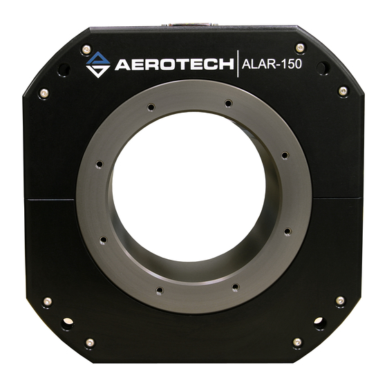
Aerotech ALAR-SP Hardware Manual (54 pages)
Large Aperture Rotary Stage
Brand:
Aerotech
| Category:
Industrial Equipment
| Size: 2 MB
Table of Contents
ALAR-SP Large Aperture Rotary Stage
1
Table of Contents
3
List of Figures
4
List of Tables
5
EU Declaration of Incorporation
6
Safety Procedures and Warnings
7
Installation and Operation
8
Electrical Warnings
9
Motor-Related Warnings
10
Pinch Points
11
Handling and Storage
12
Figure 1-1: Lifting Bolts
13
Chapter 1: Overview
15
Table 1-1: Model Numbers and Ordering Options
15
Environmental Specifications
16
Accuracy and Temperature Effects
16
Table 1-2: Environmental Specifications
16
Basic Specifications
17
Table 1-3: ALAR Series Specifications (ALAR100SP, ALAR150SP, ALAR200SP)
17
Table 1-4: ALAR Series Specifications (ALAR250SP, ALAR325SP)
18
Vacuum Operation
19
Chapter 2: Installation
21
Dimensions
21
Figure 2-1: ALAR100SP Dimensions
21
Figure 2-2: ALAR150SP Dimensions
22
Figure 2-3: ALAR200SP Dimensions
23
Figure 2-4: ALAR250SP Dimensions
24
Figure 2-5: ALAR325SP Dimensions
25
Securing the Stage to the Mounting Surface
26
Table 2-1: Stage Mounting Surface Flatness Requirement
26
Table 2-2: Stage to Mounting Surface Hardware
26
Figure 2-6: ALAR Stage Mounting Holes
27
Attaching the Payload or Fixturing to the Stage
28
Table 2-3: Mounting Interface Flatness Requirement
28
Chapter 3: Electrical Installation
29
Motor and Feedback Connectors
30
Figure 3-1: Electrical Connections
30
Table 3-1: High Power D-Style Motor Connector Pinout
31
Table 3-2: Mating Connector Part Numbers for the Motor Connector
31
Table 3-3: Feedback Connector Pinout (Incremental Encoder Options)
32
Table 3-4: Mating Connector Part Numbers for the Feedback Connector
32
Table 3-5: Feedback Connector Pinout (Absolute Encoder Option)
33
Table 3-6: Mating Connector Part Numbers for the Feedback Connector
33
Motor and Feedback Wiring
34
Figure 3-2: ALAR Motor and Feedback Wiring (Incremental Encoder Options)
34
Figure 3-3: ALAR Motor and Feedback Wiring (Absolute Encoder Option)
35
Motor and Feedback Specifications
36
Table 3-7: Hall-Effect Sensor Specifications
36
Table 3-8: Thermistor Specifications
36
Table 3-9: Encoder Specifications
36
Table 3-10: Encoder Resolution
36
Table 3-11: Maximum Speed Per Encoder Option
37
Table 3-12: Limit Switch Specifications
37
Table 3-13: ALAR-SP Motor Specifications (ALAR100SP, ALAR150SP, ALAR200SP)
38
Table 3-14: ALAR-SP Motor Specifications (ALAR250SP, ALAR325SP)
39
Limits, Marker, and Machine Direction
40
Figure 3-4: Machine Direction
40
Motor and Feedback Phasing
41
Figure 3-5: Hall Phasing Diagram
41
Figure 3-6: Encoder Phasing Reference Diagram (Standard/Square Wave)
42
Figure 3-7: Encoder Phasing Reference Diagram (Analog/Sine Wave)
42
Chapter 4: Maintenance
43
Service and Inspection Schedule
43
Cleaning and Lubrication
44
Travel Adjustment
45
Electrical Limit Adjustments
45
Mechanical Hard Stop Adjustments
46
Figure 4-1: Limit Flag Adjustment
46
Troubleshooting
47
Table 4-1: Troubleshooting
47
Appendix A: Warranty and Field Service
49
Appendix B: Revision History
51
Index
53
Advertisement
Advertisement
Related Products
Aerotech ALAR SP Series
Aerotech ALAR Series
Aerotech ALAR LP Series
Aerotech ALAR XP Series
Aerotech ALAR200SP
Aerotech ALAR100LP
Aerotech ALAR150LP
Aerotech ALAR200LP
Aerotech ALAR250XP-M1
Aerotech ALAR250XP-M2
Aerotech Categories
Industrial Equipment
DC Drives
Controller
Engine
Amplifier
More Aerotech Manuals
Login
Sign In
OR
Sign in with Facebook
Sign in with Google
Upload manual
Upload from disk
Upload from URL