Sign In
Upload
Manuals
Brands
Aeroflex Manuals
Test Equipment
2975
Aeroflex 2975 Manuals
Manuals and User Guides for Aeroflex 2975. We have
1
Aeroflex 2975 manual available for free PDF download: Operation Manual
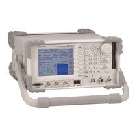
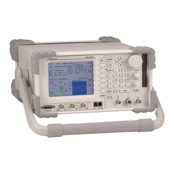
Aeroflex 2975 Operation Manual (285 pages)
Radio Test Set
Brand:
Aeroflex
| Category:
Test Equipment
| Size: 3 MB
Table of Contents
Safety Information
6
Safety Symbols
6
ESD Warning
8
Manual Scope
10
Table of Contents
12
Table of Contents
13
Supplied Items
16
Unpacking
16
Description
18
Functions and Capabilities
18
Options
21
Specifications
22
Connectors
39
Product View
39
Rear Panel
41
Operation
44
Monitor and Control Functions
45
User Screen
46
Selecting Operation Mode
47
Selecting Options
48
Zooming
49
DCS (Digital Coded Squelch)
50
Tone Signaling Decode
50
CTCSS (Continuous Tone Coded Squelch System)
51
DTMF (Dual-Tone, Multiple Frequency)
51
RF Generation On/Off Control
52
Volume and Squelch Controls
52
Setup/Recall
53
Audio I/O Connector
54
Audio Route
54
MIC Connect
54
IP Parameter Setup
55
Network Connectivity
55
Web Server Setup
55
Web Server Usage
55
Application Notes
56
Firmware Versions
56
Help Pages
56
Installed Options
56
Other Files
57
Remote Display
57
User Files
57
Demod Filter
58
Receiver Find Frequency
58
Field Definitions
59
P25 Uplink Data Tile
59
Expanded Uplink Data Tile
60
ES Data (Encryptions Synchronization)
61
Link Control
61
P25 Downlink Data
62
Lsd
64
Status Sym
64
Voice Frames
64
Frequency Entry
65
Frequency Label
65
Generator Mode 2 -
65
Operation Modes
65
Level
66
List
66
RF Generator On/Off Control
66
Sweep
66
Mod Type
67
Standard
68
Voice
68
Fm
69
M1 and M2
69
Trem
69
Ctcss
70
Dcs
70
Dtmf
70
Omega
71
SINC Config
71
Tsig
71
Arb
72
MIC
72
Freq
74
Freq Label
74
Receiver Mode 2 -
74
Atten
75
Demod
75
Input
75
Filter
76
If
76
Duplex Mode 2 -
77
Function Generator 2 -
78
Oscilloscope
82
Scope Input Options
83
Triggr (Trigger)
83
Hpos
84
LVL V / LVL Khz
84
Slope
84
Source
84
AC/DC/GND (Coupling)
85
Persist
85
V/DIV
85
Vpos
85
Average
86
Live
86
Spectrum Analyzer
86
Compare
87
Peak
87
Tracking Generator
87
Markers
88
Cable Fault Measurement Calculator
89
Quick Span
90
Sweep Speed and Zero Span
90
Rbw
91
Span
91
Auto/Man
92
Trace
92
Vbw
92
Avg
93
Normal
93
TG Output
93
Top of Scale
93
Quick Tune
94
Return
94
Tg Lvl
94
High/Low Limit
95
Range
95
SINAD Meter
95
Source Input
95
Advanced
96
C Weight
96
RF Gen Level
96
Distortion Meter
97
Power Meter 2 -
99
RSSI Meter
100
Deviation Meter
101
AM Modulation Meter
102
MOD Fidelity Meter
103
Digital (Ac/DC) Voltmeter 2 -
104
Meter Load
105
Reference Mode
105
User Load
105
Af Counter 2 -
106
RF Error Meter
107
BER Meter
108
Meter Panel
110
Checking for Installed Options
112
Optional Functions and Features
112
Section 3 - Optional Features
112
Installing Options
113
Description of Options
114
Smartnet Smartzone 900 Mhz
114
Smartnet Smartzone Testing
114
Trunking
115
Control Channel Logger
116
Octets/Messages
116
Raw Symbols
116
View Log
116
Trunking VHF/UHF/700 Mhz
117
(Sccb)
118
Secondary Control Channel Broadcast
118
Explicit Mode Operation
119
Implicit Mode Operation
119
Implicit/Explicit
119
Type 1/Type 2
119
Explicit Unit to Unit and PSTN Emulation
120
Src Addr
120
Srcid
120
Tgt Addr
120
Explicit Adjacent Status Broadcast Channel Message
121
Adjacent Site Rx Channel ID/Number
122
Adjacent Site Rx Frequency
122
C Q P S K G E N E R a T E / R E C E I V E a N D a N a L y S I S O P
123
Autotest
124
Aes
126
Automatic Loading
127
KVL Keyloader and KVL ASN
127
Manual Loading
128
A U D I O a N a L y Z E R O P
130
Audio Analyzer Option
130
A U D I O S I Mu L C a S T a L I G N O P
133
Audio Simulcast Align Option
133
L T R T R U N K I N G O P
134
LTR Trunking Option
134
R X B E R O P
134
P a S S P O R T ® O P
135
Passport Option
135
Adjacent Site Tx Channel ID/Number
122
Adjacent Site Tx Frequency
122
Digital Transmitter Testing
136
Section 4 - Applications
136
Digital Receiver Testing
141
Analog Transmitter Testing
143
Analog Receiver Testing
146
A N a L O G R E C E I V E R T E S T I N
146
Measuring Cable Fault
148
M E a S U R I N G C a B L E F a U L
148
Measuring Return Loss
150
Measuring Return Loss
151
Measuring Filters
152
M E a S U R I N G F I L T E R
152
Filter Pass Band Adjustments
154
F I L T E R P a S S B a N D a D J U S T M E N T
154
Notch Filter Adjustments
155
N O T C H F I L T E R a D J U S T M E N
155
Self Check
156
P 2 5 S E L F C H E C
156
Downlink Data Window
158
Uplink Data Window
158
Pattern Formats
159
Scope and Spectrum Analyzer
163
Project 25 Uplink Data Decoding
164
Data Unit ID
165
LCO - Link Control Op Code / LCF Link Control Format
166
MFID - Manufacturer's ID
166
P - Protected Flag
166
SF - Implicit/Explicit MFID Format
166
Standard MFID Values
167
Connecting to the Unit
170
Section 5 - Remote Commands
170
Introduction
170
Gpib
171
Rs-232
171
Telnet over Ethernet
172
Delaying
173
Issuing Commands
173
TCL Basics
173
Variables
173
Defining Procedures
174
Finding out What Went Wrong (Errorinfo)
174
-Onchangecommands-Usingevents
175
Controlling the Unit
175
Controlling the 2975 Display
176
Recalling Saved Instrument States
177
Command Name/Subcommand Name
179
Data Retrieval or Modification
179
Data Returned by the Command
179
U S I N G T H E 2 9 7 5 T C L C O M M a N D V E R B
179
Using TCL Command Verbs
179
Command Modifiers
180
Minimize or Avoid Screen Changes
181
R E Mo T E T E S T R E C O M M E N D a T I O N
181
Structure Test Procedures
181
Test Speed Limitations
181
Command/Response Issues
182
Unhandled Data Responses
182
Use GPIB “Read” to Remove Unwanted Data
182
Avoid Generating a Response for Unwanted Data
183
Detecting and Correcting Loss of Command/Reply Sync.
183
Using an Aeroflex CVI Driver
184
Q U I C K R E F E R E N C E L I S
185
Quick Reference List
185
Commands
195
Audio Frequency Counter
198
Bit Error Rate - Ber
201
Bbaudio
203
C4FM (Continuous 4-Level Frequency Modulation)
207
Digital Coded Squelch - DCS
212
Digital Voltmeter (DVM)
213
Distortion
217
FM Deviation
221
Function Generators
224
Generator
227
Hw_Control
230
Logic Trunked Radio - Ltr
232
P25
238
Power
243
Receiver
245
RF Error
248
Rlmeter (Narrowband)
251
Scope
253
Sinad
256
Configuration
262
Section 6 - System Settings
262
General
262
C O N F I G U R a T I O N
262
I E E E - 4 8 8 ( G P I B ) S E T U P
263
I P P a R a Me T E R S E T U P
263
IEEE-488 (GPIB) Setup
263
S y S T E M P a R a Me T E R S E T U P
263
System Parameter Setup
263
F a C T O R y D E F a U L T ( F 2 )
264
Factory Default
264
R S - 2 3 2 ( S E R I a L ) S E T U P
264
RS-232 (Serial) Setup
264
T I Me / D a T E
264
Time/Date
264
Version
265
E R S I O N
265
R E L O a D
265
Calibrations
266
Save/Recall
266
C a L I B R a T I O N S
266
S a V E / R E C a L L
266
Connector Pin-Out Tables
268
Table of I/O Connectors
268
Pin-Out Table for Audio I/O Connector
269
Pin-Out Table for GPIB Connector
270
Pin-Out Table for RS-232 Connector
271
Pin-Out Table for Printer Connector
272
Pin-Out Table for Test Port Connector
273
Pin-Out Table for Keyboard Connector
274
Pin-Out Table for Mouse Connector
274
Pin-Out Table for Ethernet Connector
275
Pin-Out Table for USB Connector
275
Appendix B - Repacking for Shipment
276
Authorization
276
Freig Ht Co Sts
276
Repacking Procedure
276
Shipping Containers
276
Tag G Ing Test Sets
276
Terminology
278
Index
280
Advertisement
Advertisement
Related Products
Aeroflex ProLock 2201
Aeroflex TETRA Stabilock 2305
Aeroflex 2945A
Aeroflex 2945B
Aeroflex 2946A
Aeroflex 2948
Aeroflex 2948B
Aeroflex 2944B
Aeroflex 2051T
Aeroflex 2024
Aeroflex Categories
Test Equipment
Measuring Instruments
Control Unit
Portable Generator
Inverter
More Aeroflex Manuals
Login
Sign In
OR
Sign in with Facebook
Sign in with Google
Upload manual
Upload from disk
Upload from URL