Sign In
Upload
Manuals
Brands
Aeroflex Manuals
Inverter
2051T
Aeroflex 2051T Manuals
Manuals and User Guides for Aeroflex 2051T. We have
1
Aeroflex 2051T manual available for free PDF download: Operating Manual
Aeroflex 2051T Operating Manual (322 pages)
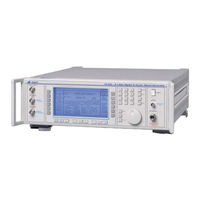
2050T SERIES DIGITAL & VECTOR SIGNAL GENERATOR
Brand:
Aeroflex
| Category:
Inverter
| Size: 3.17 MB
Table of Contents
General Information
21
About this Manual
3
General Information
6
Table of Contents
21
Introduction
22
Main Features
22
Operation
23
Display
23
Frequency Selection
23
Output
23
Modulation
24
Vector Modulation
24
Digital Modulation
25
Incrementing
25
Sweep
26
Non-Volatile Memory
26
Programming
26
Software Protection
26
Spectral Purity
26
Calibration
26
Options
27
Fig. 1-1 Typical Phase Noise Performance of 2050T Series in Non-Digital and -Vector Modes
27
Performance Data
28
General Information
28
Installation
34
Versions, Options and Accessories
36
Installation
38
Initial Visual Inspection
39
Installation Requirements
39
Ventilation
39
Class I Power Cords (3-Core)
39
Mounting Arrangements
39
Goods-In Checks
41
Connecting to Supply
42
Voltage Selector
42
Fuses
42
General Purpose Interface Bus (GPIB)
43
GPIB Cable Connection
43
GPIB Connector Contact Assignments
43
IEEE to IEC Conversion
44
Interface Bus Connection
44
Auxiliary I/O Connector
45
Modulation Data
45
Power Supply Outputs
45
Table 2-1 Modulation Data Contact Assignments
45
Auxiliary Outputs
46
Rack Mounting
46
Routine Maintenance
47
Safety Testing and Inspection
47
Battery Replacement
48
Cleaning
49
Cleaning the LCD Window
49
Putting into Storage
49
Operation
50
Conventions
55
Front Panel
55
Introduction
55
Rear Panel
57
The Menus
58
First-Time Use
59
Switching on
59
Changing the Value of the Selected Parameter
59
Enabling or Disabling the Modulation
60
Using the [ ×10] and [ ÷10] Keys
60
Using the Control Knob
60
Carrier Frequency
61
Carrier ON/OFF
61
Detailed Operation
61
Output Level
61
Choice of Units
61
Reverse Power Protection
61
Modulation
62
Complex Modulation Modes
62
Analog Modulation Modes
62
Modulation Mode Selection
63
Digital Modulation
65
Setting the Output Carrier
65
Self-Calibration
65
Setting the Digital Modulation System
66
Modulation Type and System Selection
66
Storing a User-Defined System
68
Cellular Systems Selection
69
Paging Systems Selection
69
PMR Systems Selection
71
Avionic/Satellite Systems Selection
72
Cordless Systems Selection
73
Creating a Modulation System
73
Selecting the Modulation Type
74
QAM Selection Menu
75
PSK Selection Menu
75
FSK Selection Menu
76
Symbol Rate Setting
76
Filter Selection
77
Parameter Constraints
78
Digital Modulation Mode
65
Test Tones Utility
79
Test Tones Operation
79
Data/Timing
80
Data
80
Timing
81
Selecting Internal Data
81
Digital Data Mapping
82
Psk
82
Bpsk (2Psk)
82
Qpsk (4Psk)
82
8Psk
83
Time Offset QPSK
83
Differential PSK
83
Phase Offset Differential PSK
84
Qam
85
4Qam
86
64QAM and 256QAM
87
Fsk
87
4FSK (Grey Coded, Normal Mapping)
87
4FSK (Grey Coded, Inverse Mapping)
87
Modulation Configuration
88
IQ Output Enable
88
Mixer Selection
89
Pulse Input Selection (Applies if Option 002 Fitted)
89
Sideband and if Selection
90
Modulation Polarity
90
External Envelope
90
Modulation Fading
91
IQ Modulator Errors
92
Advanced Digital Modulation
93
Setting the Output Carrier
93
Self-Calibration
93
Modulation Type and System Selection
93
Advanced Digital Modulation Mode
93
Vector Modulation
94
Setting the Output Carrier
94
Self-Calibration
94
Vector Modulation Mode
94
Modulation Configuration
95
Mixer Selection
96
IQ Input Impedance Selection
96
Pulse Input Selection (Applies if Option 002 Fitted)
97
Sideband and if Selection
97
Modulation Polarity
97
External Envelope
97
Modulation Fading
98
Analog Modulation
99
Selecting the Modulation
99
Modulation ON/OFF
99
Selecting Amplitude Modulation
100
Selecting Frequency Modulation
100
Selecting Phase Modulation
100
Selecting Wideband Frequency Modulation
100
Modulation Source Frequency
100
Source Selection - Internal
101
Lf Phase
102
Source Selection - External
102
Analog Modulation Mode
99
Modulation ALC
103
Pulse Modulation
103
Selecting the Pulse Modulation Mode
103
Selecting Pulse Modulation
104
Low Intermodulation Mode
105
Signalling
106
Ctcss
106
Sequential Calling Tones
107
Incrementing (Using Δ)
111
Displaying Shifts
111
Setting Increment Values
111
Sweep
112
Sweep Type
113
Sweep Mode
114
Sweep Parameter Entry
114
Number of Steps
114
Option 012 Electronic Attenuator Appendix C 6-1
115
Second Modulation Oscillator Appendix A 6-1
115
Step Time
115
Sweep Control
116
Utilities
118
Adjusting the Display
118
Hardware Information
119
Software Information
119
External Trigger
119
Setting the Modulation Mode
119
Setting the GPIB Address
119
Sequential Calling Tones
119
Carrier Phase Adjustment
120
Selection of Frequency Standard
120
Latch Data Utility
121
Selection Menu 2
123
Calibration
124
Latch Data
124
Elapsed Time
124
Locking and Unlocking
124
Setting Time and Date
125
Keyboard Locking
125
Display Blanking
125
Power up Options
125
RF Level Units
126
LF Level Units
127
RF Level Utility
127
Extended Hysteresis
128
Low Frequency Operation
132
LF Monitor
132
Modulation Source Monitoring
132
Modulation Drive Monitoring
132
Use as an Independent LF Generator
133
Memory
134
Memory Recall
134
Memory Stepping Facility
135
Memory Store
136
Frequency Hopping
138
Store Erase
138
Error Handling
141
Background Errors
141
Foreground Errors
141
GPIB Errors
141
Error Display
141
Gpib Operation
145
GPIB Functions
146
Introduction
146
Device Listening Elements
147
Device Talking Elements
147
Programming
148
Program Messages
148
Compound Headers
148
Program Data
148
Message Exchange Protocol
149
Remote/Local Operation
149
Common Commands and Queries (IEEE 488.2)
149
Default Settings
151
Device Dependent Commands
151
Carrier Frequency
153
Instrument Mode
153
RF Level
154
Modulation Control
156
Modulation Mode
156
Digital Modulation
157
Advanced Digital Modulation
165
Vector Modulation
170
Frequency Modulation
172
Phase Modulation
173
Amplitude Modulation
174
Wideband FM
175
Pulse Modulation
176
Modulation Frequency
177
CTCSS Tones Edit
178
Sequential Tones
179
LF Control
181
LF Generator Frequency
182
LF Generator Level
183
Memory - Erase
184
Memory - Recall
184
Memory - Store
184
Sweep Operation
185
Sweep Mode/Type
188
Frequency Hopping
189
Sweep Control
189
Miscellaneous Commands
190
The Status Byte
192
Status Data Structure - Register Model
193
Standard Event Registers
194
Hardware Event Registers
195
Coupling Event Registers
196
Instrument Event Registers
197
Queue Flag Details
198
Status Byte When Read by *Stb
199
Status Byte When Read by Serial Poll
200
Summary of Status Reporting Commands and Queries
201
Acceptance Testing
204
Introduction
206
Recommended Test Equipment
206
RF Output
207
ALC Linearity
208
Attenuator Accuracy
209
Alternative Attenuator Functional Check
210
Test Procedures
207
Carrier Frequency Accuracy
211
Modulation Oscillator
212
Modulation Oscillator Frequencies
212
Modulation Oscillator Distortion
213
LF Output
214
Frequency Response
215
External Modulation
216
Mod ALC on Flatness
216
Modulation ALC Distortion
217
Internal am Depth and Distortion
218
AM Scale Shape
219
Phase Modulation on am
219
External am
220
Internal FM Deviation
221
FM Attenuator
221
FM Scale Shape
222
External FM
223
Carrier Frequency Offset
225
Internal Phase Modulation
226
Internal Phase Modulation Flatness
226
Spectral Purity
227
Residual FM
227
Carrier Harmonics
228
Carrier Sub-Harmonics (2051T and 2052T Only)
229
Non-Harmonics
230
SSB Phase Noise
231
Digital Modulation Mode
232
IQ Outputs
232
Level Accuracy
234
Modulation Accuracy
236
Burst Control
240
Advanced Digital Mode
240
Adjacent Channel Performance
240
Vector Modulation Mode
241
Vector Input Impedance
241
DC Vector Accuracy
241
Vector Bandwidth
243
Envelope Control
244
Linearity
244
On/Off Ratio
245
Envelope Delay
245
IF Output
246
Last Complete Check Date
246
Calibration Due Date
247
Real Time Clock Battery
247
Appendix A Acceptance Testing Second Modulation Oscillator Option
248
Modulation Oscillators
249
Modulation Oscillator Frequencies
249
Modulation Oscillator Distortion
250
LF Output
251
Level Accuracy
251
Frequency Response
252
AM Scale Shape
253
FM Scale Shape
254
Appendix A ACCEPTANCE TESTING SECOND
255
Chapter 1 GENERAL INFORMATION
255
Acceptance Testing Pulse
255
Chapter 2 INSTALLATION
255
Chapter 3 OPERATION
255
Chapter 4 GPIB OPERATION
255
Chapter 5 BRIEF TECHNICAL DESCRIPTION
255
Chapter 6 ACCEPTANCE TESTING
255
Appendix C Acceptance Testing Electronic Attenuator
258
Acceptance Testing Electronic
258
Appendix B ACCEPTANCE TESTING PULSE
258
Electronic Attenuator
258
Test Procedures
259
RF Output
260
ALC Linearity
260
Attenuator Accuracy
260
Alternative Attenuator Functional Check
261
Annex a Option 006 Avionics
262
Annex a
262
Option 001 Second LF Oscillator Appendix A 6-1 Safety Testing (Routine) 2-10
262
Option 002 Pulse Modulation Appendix B 6-1
262
Option 006 Avionics
262
ADF Mode
264
General Description
264
ILS Mode
264
Marker Beacon Mode
264
SEL-CAL Mode
264
VOR Mode
264
ILS Mode
265
Marker Beacon Mode
265
Performance Data
265
VOR Mode
265
ADF Mode
266
Sel-Cal Mode
266
ILS Mode
268
Localiser/Glideslope Frequency Conversion
270
Communication Channel Testing
271
Marker Beacon Mode
272
Tone Phase Variability
272
Sub-Carrier Peak Deviation
273
VOR Mode
273
ADF Mode
276
Identity Channel
276
SEL-CAL Mode
277
Rotary Control
278
GPIB Operation
279
ILS (Instrument Landing System) Mode
280
Marker Beacon Mode
282
VOR (VHF Omnidirectional Radio Range) Mode
283
ADF (Automatic Direction Finder) Mode
285
Sel-Cal Mode
285
Acceptance Testing
286
Functional Testing of ILS Waveform Generation
286
Introduction
286
Test Equipment
286
Accuracy of SDM (Sum Depth of Modulation) Signal Path
291
Accuracy of DDM (Difference Depth of Modulation) Waveform
292
VOR Waveform Depth Accuracy
294
VOR Waveform Test
295
Waveform Phase Control
296
Annex B Option 008 Rf Profiles and Complex Sweep
297
Option 008 Rf Profiles and Complex
297
Performance Data
298
RF Profile
298
Segmented Sweep
298
Modulation Waveforms
298
Introduction to Option 008
299
RF Offset and Profiles
299
Access to RF Offset and Profile
300
RF Offset
300
RF Profiles
302
Creating a Profile
303
Enabling a Profile
304
Tutorial Examples for RF Offset and Profiles
305
Sequence Sweep
306
Selecting a Sequence Sweep
307
Modifying Segments
308
Entering a Sweep Sequence
309
Sweep Mode
309
Starting to Sweep
309
Tutorial Examples for Sequence Sweep
310
Complex Sweeps
310
RF Profiles, Offset and Sequence Sweep
310
Suppressing Attenuator Changes
311
Tutorial Example for Immunity Testing
311
Square Wave Modulation
312
GPIB Operation
313
Segmented Sweeps
313
RF Profiles
314
RF Offsets
315
Advertisement
Advertisement
Related Products
Aeroflex 2050T SERIES
Aeroflex 2023A
Aeroflex 2023B
Aeroflex 2025
Aeroflex 2052T
Aeroflex 2030 Series
Aeroflex DATATRAC 200
Aeroflex 2023
Aeroflex 2024
Aeroflex 2975
Aeroflex Categories
Test Equipment
Measuring Instruments
Control Unit
Portable Generator
Marine Radio
More Aeroflex Manuals
Login
Sign In
OR
Sign in with Facebook
Sign in with Google
Upload manual
Upload from disk
Upload from URL