
Related Manuals for Aeroflex 2050T SERIES


Summary of Contents for Aeroflex 2050T SERIES
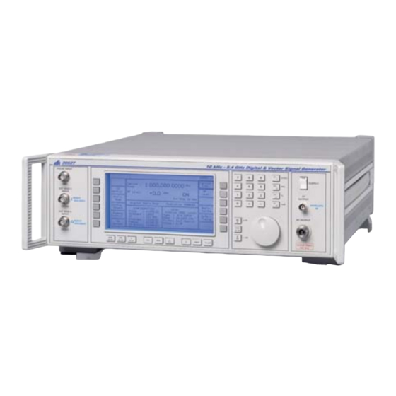
- Page 1 DIGITAL & VECTOR SIGNAL GENERATOR 2050T SERIES Operating Manual Document part no. 46892/296 Issue 14 15 May 2007...
- Page 2 Aeroflex International Ltd. (hereafter referred to throughout the document as ‘Aeroflex’). Manual part no. 46892/296 (PDF version) Based on Issue 14 of the printed manual.
-
Page 3: About This Manual
About this manual This manual explains how to use the 2050T series of Digital & Vector Signal Generators. Intended audience Persons engaged on work relating to equipment who have a need for accurately generated signals in the VHF and UHF spectrum. - Page 4 Contents numbers Preface Precautions Precautions Vorsichtsmaßnahmen Precauzioni Precauciones Chapter 1 GENERAL INFORMATION Chapter 2 INSTALLATION Chapter 3 OPERATION Chapter 4 GPIB OPERATION Chapter 5 BRIEF TECHNICAL DESCRIPTION Chapter 6 ACCEPTANCE TESTING Appendix A ACCEPTANCE TESTING SECOND MODULATION OSCILLATOR OPTION Appendix B ACCEPTANCE TESTING PULSE MODULATION OPTION Appendix C...
- Page 5 Preface Patent protection The 2050T series Digital & Vector Signal Generators are protected by the following patents: GB 2030391 GB 2214012 US 4323943 US 4870384 FR 80.26256 GB 1601822 GB 2064892 US 4194164 US 4400630 EP 0125790 GB 2158999 GB 2140232...
-
Page 6: General Information
Precautions These terms have specific meanings in this manual: WARNING information to prevent personal injury. information to prevent damage to the equipment. important general information. Hazard symbols The meaning of hazard symbols appearing on the equipment and in the documentation is as follows: Symbol Description... - Page 7 Fuses Note that there are supply fuses in both the live and neutral wires of the supply lead. If only one of these fuses should rupture, certain parts of the equipment could remain at supply potential. For Option 100, single fuse version only: Fuses Note that the internal supply fuse is in series with the live conductor of the supply lead.
- Page 8 This equipment has been designed and manufactured by Aeroflex to generate low-power RF signals for testing radio communications apparatus. If the equipment is not used in a manner specified by Aeroflex, the protection provided by the equipment may be impaired.
- Page 9 Précautions Les termes suivants ont, dans ce manuel, des significations particulières: WARNING contient des informations pour éviter toute blessure au personnel. contient des informations pour éviter les dommages aux équipements. contient d'importantes informations d'ordre général. Symboles signalant un risque La signification des symboles de danger apparaissant sur l'équipement et dans la documentation est la suivante: Symbole Nature du risque...
- Page 10 Notez que les filtres d’alimentation contiennent des condensateurs qui peuvent encore être chargés lorsque l’appareil est débranché. Bien que l’énergie contenue soit conforme aux exigences de sécurité, il est possible de ressentir un léger choc si l’on touche les bornes sitôt après débranchement.
- Page 11 Utilisation Cet équipement a été conçu et fabriqué par Aeroflex pour générer des signaux RF de faible puissance pour le test d'appareils de radio communications. La protection de l'équipement peut être altérée s'il n'est pas utilisé dans les conditions spécifiées par Aeroflex.
- Page 12 Vorsichtsmaßnahmen Diese Hinweise haben eine bestimmte Bedeutung in diesem Handbuch: WARNING dienen zur Vermeidung von Verletzungsrisiken. dienen dem Schutz der Geräte. enthalten wichtige Informationen. Gefahrensymbole Die Bedeutung der Gefahrensymbole auf den Geräten und in der Dokumentation ist wie folgt: Symbol Gefahrenart Beziehen Sie sich auf die Bedienungsanleitung wenn das Messgerät mit diesem Symbol markiert ist.
- Page 13 Lassen Sie alle Reparaturen durch qualifiziertes Personal durchführen. Eine Liste der Servicestellen finden Sie auf der Rückseite des Handbuches. Sicherungen Es ist zu beachten, daß es Sicherungen in beiden (spannunsführenden und neutralen) Zuleitungen gibt. Wenn nur eine von diesen Sicherungen schmilzt, so bleiben einige Geräteteile immer noch auf Spannungspotential.
- Page 14 Dieses Gerät wurde von Aeroflex entwickelt und hergestellt um HF Signale geringer Leistung zum Test von Kommunikationseinrichtungen zu erzeugen. Sollte das Gerät nicht auf die von Aeroflex vorgesehene Art und Weise verwendet werden, kann die Schutzfunktion des Gerätes beeinträchtigt werden.
- Page 15 Precauzioni Questi termini vengono utilizzati in questo manuale con significati specifici: WARNING riportano informazioni atte ad evitare possibili pericoli alla persona. riportano informazioni per evitare possibili pericoli all'apparecchiatura. riportano importanti informazioni di carattere generale. Simboli di pericolo Il significato del simbolo di pericolo riportato sugli strumenti e nella documentazione è il seguente: Simbolo Tipo di pericolo Fare riferimento al manuale operativo quando questo...
- Page 16 Non rimuovete mai le coperture perché così potreste provocare danni a voi stessi. Non vi sono all’interno parti di interesse all’utilizzatore. Tutte gli interventi sono di competenza del personale qualificato. Vedi elenco internazionale dei Centri di Assistenza in fondo al manuale. Fusibili Notare che entrambi i capi del cavo d’alimentazione sono provvisti di fusibili.
- Page 17 Caratteristiche d’uso Questo strumento è stato progettato e prodotto da Aeroflex generare segnali RF in bassa potenza per provare apparati di radio comunicazione. Se lo strumento non è utilizzato nel modo specificato da Aeroflex, le protezioni previste sullo strumento potrebbero risultare inefficaci.
- Page 18 Precauciones Estos términos tienen significados específicos en este manual: WARNING contienen información referente a prevención de daños personales. contienen información referente a prevención de daños en equipos. contienen información general importante. Símbolos de peligro El significado de los símbolos de peligro en el equipo y en la documentación es el siguiente: Símbolo Naturaleza del peligro Vea el manual de funcionamiento cuando este símbolo...
- Page 19 Deje todas las tareas relativas a reparación a un servicio técnico cualificado. Vea la lista de Centros de Servicios Internacionales en la parte trasera del manual. Fusibles Se hace notar que el Equipo está dotado de fusibles tanto en el activo como el neutro de alimentación.
- Page 20 él. Idoneidad de uso Este equipo ha sido diseñado y fabricado por Aeroflex para generar señales de VHF y UHF de bajo nivel de potencia para prueba de equipos de radiocomunicaciones. Si el equipo fuese utilizado de forma diferente a la especificada por Aeroflex, la protección ofrecida por el equipo pudiera quedar reducida.
-
Page 21: Table Of Contents
Software protection ......................1-6 Spectral purity ........................1-6 Calibration ..........................1-6 Options ..........................1-7 Performance data ......................... 1-8 Versions, options and accessories ..................... 1-16 List of figures Fig. 1-1 Typical phase noise performance of 2050T Series in non-digital and -vector modes .. 1-7... -
Page 22: Introduction
GENERAL INFORMATION Introduction The 2050T series Digital and Vector Signal Generators offer a wide range of analog and digital modulation facilities covering the frequency ranges 10 kHz to 5.4 GHz with three models: 2050T (10 kHz to 1.35 GHz), 2051T (10 kHz to 2.7 GHz) and 2052T (10 kHz to 5.4 GHz). A dot matrix display with soft key selected screen options allow flexibility of operation and ease of use. -
Page 23: Operation
GENERAL INFORMATION Operation Selection of parameters on the screen may involve one or more of the numeric, hard or soft keys or the rotary knob. Hard keys have single or dual functions which remain constant throughout, whereas soft keys have functions dependent on the present mode of operation. Parameters may be set to specific values by numeric key entry, while values may be varied in steps of any size using keys or altered by moving the knob, set to a particular sensitivity. -
Page 24: Modulation
Both AC and DC coupled FM is available. In the DC coupled FM mode a patented offset correction system eliminates the large carrier frequency offsets that occur with normal signal generators. As a result the 2050T series signal generators can be used confidently for testing tone and message paging equipment. -
Page 25: Digital Modulation
GENERAL INFORMATION Digital modulation In addition to the wideband analog I and Q inputs a digital mode of operation is provided. This allows the user to generate a vector modulated RF carrier from digital data inputs. The bandwidth of the digital mode is sufficient to simulate radio systems which have been designed to work in the frequency allocation of an analog voice channel. -
Page 26: Sweep
Harmonically related signals and non-harmonics are better than -30 dBc and -70 dBc respectively. Calibration The 2050T Series has a recommended two year calibration interval and is calibrated entirely by electronically controlled adjustment. There are no internal mechanically adjustable components to affect the calibration. -
Page 27: Options
SSB Phase -100 Noise (dBc/Hz) -120 Noise (dBc/Hz) -110 -120 -130 -130 -140 -150 -140 -160 1000 2000 100k Carrier Frequency (MHz) Frequency Offset (Hz) C0079 Fig. 1-1 Typical phase noise performance of 2050T Series in non-digital and -vector modes... -
Page 28: Performance Data
GENERAL INFORMATION Performance data Carrier frequency Range 10 kHz to 1.35 GHz (2050T); 10 kHz to 2.7 GHz (2051T); 10 kHz to 5.4 GHz (2052T). In digital and vector modes the lowest frequency is 10 MHz and for 2050T the highest frequency is reduced to 2.7 GHz. Selection By keyboard entry of data. - Page 29 GENERAL INFORMATION Spectral purity (analog mode) At RF levels up to +7 dBm in CW and analog modulation modes:- Harmonics 2050T, 2051T: Better than −30 dBc for carrier frequencies to 1 GHz; Better than −27 dBc for carrier frequencies from 1 GHz to 1.35 GHz. Better than −27 dBc for carrier frequencies above 1.35 GHz.
- Page 30 GENERAL INFORMATION Frequency modulation Deviation Peak deviation from 0 to 1 MHz for carrier frequencies up to 21.09375 MHz; Peak deviation from 0 to 1% of carrier frequency above 21.09375 MHz. Selection By keyboard entry of data. Variation by keys and by rotary control.
- Page 31 GENERAL INFORMATION Amplitude modulation For carrier frequencies up to 1 GHz: Range 0 to 99.9%. Selection By keyboard entry of data. Variation by keys and by rotary control. Resolution 0.1% Indication 3 digits with annunciator. ±4% of setting ±1%. Depth accuracy at 1 kHz External AM 1 dB bandwidth With modulation ALC off;...
- Page 32 GENERAL INFORMATION Predefined modulation types The following can be selected: Modulation type System π /4 DQPSK NADC (DAMPS), PDC (JDC), TETRA, APCO25, TFTS GMSK GSM, Mobitex, CDPD, MC9, DSRR, MD24-192N/W, Modacom POCSAG, CITYRUF 4FSK ERMES, APCO25 OQPSK Inmarsat 'M' 8DPSK VDR (VDL) Modulation accuracy At the decision points with the envelope input at 1 V or disabled, and...
- Page 33 GENERAL INFORMATION IQ modulation calibration The signal generator can calibrate the vector modulator automatically. After a hour warm-up period the calibration remains valid for at least three hours over a temperature range of ±5°C. The instrument displays a warning if the calibration validity time or temperature range has been exceeded.
-
Page 34: Installation
GENERAL INFORMATION LF output Front panel BNC connector. The output may be configured in either LF Generator Mode to give an output from the internal modulation oscillator or in LF Monitor Mode to give an output from the internal modulation signal paths. Selection By keyboard entry of data. - Page 35 GENERAL INFORMATION Conditions of storage and transport −40°C to +71°C. Temperature Humidity Up to 93% relative humidity at 40°C. Altitude Up to 4600 m (15,000 ft). Power requirements AC supply Four voltage settings covering 100 V~ (limit 90–115 V~) 120 V~ (limit 105–132 V~) 220 V~ (limit 188–242 V~) 240 V~ (limit 216–264 V~) Frequency: 50–400 Hz (limit 45 Hz–440 Hz) 180 VA max.
-
Page 36: Versions, Options And Accessories
External modulation inputs (2) 600 Ω impedance. Option 112 Supplied accessories AC supply lead (see 'Power cords', Chap. 2). 46882/296 Operating manual (this manual) for 2050T series. Optional accessories Service manual for 2050T series. 46880/078 RF connector cable, double screened, 50 Ω, 1.5 m, BNC. - Page 37 GENERAL INFORMATION EC Declaration of Conformity Certificate Ref. No.: DC227 The undersigned, representing: Manufacturer: Aeroflex International Ltd. Address: Longacres House, Six Hills Way, Stevenage, Hertfordshire, UK SG1 2AN Herewith declares that the product: Equipment Description: Digital and Vector Signal Generators Model No.
- Page 38 Chapter 2 INSTALLATION Contents Initial visual inspection........................ 2-2 Mounting arrangements....................... 2-2 Installation requirements ......................2-2 Ventilation ..........................2-2 Class I power cords (3-core) ....................2-2 Goods-in checks .......................... 2-4 Connecting to supply........................2-5 Voltage selector........................2-5 Fuses............................. 2-5 General purpose interface bus (GPIB)..................2-6 GPIB cable connection......................
-
Page 39: Initial Visual Inspection
In the event that a moulded plug has to be removed from a lead, it must be disposed of immediately. A plug with bare flexible cords is hazardous if engaged in a live socket outlet. Power cords with the following terminations are available from Aeroflex. Please check with your local sales office for availability. - Page 40 INSTALLATION British Country IEC 320 plug type Part number United Kingdom Straight through 23422/001 United Kingdom Right angled 23422/002 EARTH NEUTRAL The UK lead is fitted with an ASTA approved moulded plug to BS LIVE 1363. A replaceable 13 A fuse to BS 1362 is contained within the plug. This UNITED KINGDOM fuse is only designed to protect the lead assembly.
-
Page 41: Goods-In Checks
Inspect the shipping container and instrument for any signs of damage. If damage is evident, do not plug in, turn on or attempt to operate the instrument. Repackage it and return it to Aeroflex. Verify that your order is complete, including any accessories and options that you may have ordered. -
Page 42: Connecting To Supply
INSTALLATION Connecting to supply The instrument is a Safety Class 1 product and therefore must be earthed. Use the supplied power cord or an appropriate replacement. Make sure that the instrument is plugged into an outlet socket with a protective earth contact. Disconnecting device The detachable power cord is the instrument’s disconnecting device, but if the instrument is integrated into a rack or system, an external power switch or circuit breaker may be required. -
Page 43: General Purpose Interface Bus (Gpib)
INSTALLATION General purpose interface bus (GPIB) The GPIB interface built into the 2050T series enables the signal generators to be remotely controlled to form part of an automatic measuring system. GPIB cable connection Connection to other equipment which has a 24-way connector to IEEE Standard 488 is made using the rear panel GPIB socket. -
Page 44: Ieee To Iec Conversion
INSTALLATION IEEE to IEC conversion An optional IEEE to IEC adapter is also available (see Chap. 1 'Optional Accessories') for interfacing with systems using a 25-way bus connector to IEC Recommendation 625. The method of use is shown in Fig. 2-3. IEEE LEAD INSTRUMENT EQUIPMENT... -
Page 45: Auxiliary I/O Connector
INSTALLATION Auxiliary I/O connector The rear panel 25-way female D-type AUXILIARY I/O connector is shown in Fig. 2-4. This carries modulation data inputs and power supply outputs as well as having contacts used for external control. C0681 Fig. 2-4 25-way AUXILIARY I/O connector Modulation data Data for the modulator and burst control are carried on the contacts for the various formats as shown by Table 2-1. -
Page 46: Auxiliary Outputs
INSTALLATION Auxiliary outputs The following outputs can be used for controlling external devices: AUX 0 contact 1 AUX 1 contact 2 AUX 2 contact 3 AUX 3 contact 4 AUX 4 contact 5 AUX 5 contact 6 AUX 6 contact 7 AUX 7 contact 8 AUX ENABLE... -
Page 47: Routine Maintenance
INSTALLATION Routine maintenance Safety testing and inspection In the UK, the ‘Electricity at Work Regulations’ (1989) section 4 (2) places a requirement on the users of equipment to maintain it in a safe condition. The explanatory notes call for regular inspections and tests together with a need to keep records. -
Page 48: Battery Replacement
The above information is provided for guidance only. Aeroflex designs and constructs its products in accordance with International Safety Standards such that in normal use they represent no hazard to the operator. Aeroflex reserves the right to amend the above information in the course of its continuing commitment to product safety. -
Page 49: Cleaning
INSTALLATION Cleaning Before commencing any cleaning, switch off the instrument and disconnect it from the supply. The exterior surface of the case may be cleaned using a soft cloth moistened in water. Do not use aerosol or liquid solvent cleaners. Cleaning the LCD window To prevent damage to the LCD window, care should be taken not to scratch the surface during use and also when cleaning. - Page 50 Chapter 3 OPERATION Contents Introduction ..........................3-6 Conventions..........................3-6 Front panel........................... 3-6 Rear panel............................ 3-8 The menus ........................... 3-9 First-time use ........................... 3-10 Switching on........................3-10 Changing the value of the selected parameter ..............3-10 Enabling or disabling the modulation................. 3-11 ×10] and [ ÷10] keys .................
- Page 51 OPERATION 8PSK........................... 3-34 Time offset QPSK ......................3-34 Differential PSK ......................... 3-34 Phase offset differential PSK..................... 3-35 QAM............................3-36 4QAM..........................3-37 16QAM..........................3-37 64QAM and 256QAM ....................... 3-38 FSK............................3-38 2FSK........................... 3-38 4FSK (Grey coded, normal mapping) ................3-38 4FSK (Grey coded, inverse mapping) ................3-38 Modulation configuration ......................
- Page 52 List of figures Fig. 3-1 2051T front panel......................3- 1 5 9 H Fig. 3-2 2051T rear panel ......................3- 1 6 0 H Fig. 3-3 Sig Gen menu - default display for 2050T series............3- 1 6 1 H...
- Page 53 OPERATION Fig. 3-4 Amplitude modulation - menu configuration.............. 3-11 Fig. 3-5 RPP tripped ......................... 3-13 Fig. 3-6 Modulation mode selection menu ................3-14 Fig. 3-7 Sig Gen menu with two modulation channels (composite mode)....... 3-15 Fig. 3-8 Sig Gen menu in digital modulation mode ..............3-16 Fig.
- Page 54 OPERATION Fig. 3-61 Total shift menu ......................3-62 Fig. 3-62 Sweep parameters display..................3-64 Fig. 3-63 Sweep type menu ...................... 3-64 Fig. 3-64 Sweep trigger mode menu ..................3-65 Fig. 3-65 Sweep markers menu ....................3-66 Fig. 3-66 Sweep in progress ..................... 3-67 Fig.
-
Page 55: Introduction
OPERATION Introduction This chapter explains how to: • Set up the signal generator to produce a typical basic signal. • Select the main operating parameters; carrier frequency, output level and type of modulation. • Use the full range of supporting facilities. Note... - Page 56 OPERATION Displays the LF and monitor menus. SWEEP Displays the sweep status menu. (10) SIG GEN Displays the main menu. (11) SOFT KEYS Twelve function keys change notation as the menu changes. (12) NUMERICAL For changing the value of a selected parameter. Minus sign KEY PAD and decimal point are included.
-
Page 57: Rear Panel
OPERATION Rear panel The following facilities are available on the rear panel, see Fig. 3-2. ------------ ------------ MARKER RAMP TRIGGER WIDE BAND FREQ STD FM IN IN/OUT SWEEP FUSE 100/120V~ TT1.6AL250V GPIB RATING 220/240V~ TT1AL250V 220Vac POWER SUPPLY 100/120/220/240V~ 240Vac 50-400Hz 180VA MAX OUTPUT... -
Page 58: The Menus
OPERATION The menus The 2050T Series instruments are operated by calling up various displays or menus on the screen. Menus are accessed via both hard and soft keys. Pressing a hard key normally causes the appropriate primary menu to appear on the screen regardless of the current working position within the menu hierarchy. -
Page 59: First-Time Use
Alternatively use the [MEM] key followed by entering 50 and terminating by pressing the [enter] key. This will reset the instrument to the 2050T series default setting. If the RF level units and the internal/external standard are not as shown, they can be changed as described on Page 3-77, 'RF level units' and Page 3-71 'Selection of frequency standard'. -
Page 60: Enabling Or Disabling The Modulation
OPERATION Enabling or disabling the modulation The modulation is ON by default, but the AM can be turned ON and OFF by pressing [AM ON/OFF] at the right hand side of the display and the modulation can be enabled or disabled by pressing [MOD ON-OFF]. -
Page 61: Detailed Operation
OPERATION Detailed operation Carrier frequency The carrier frequency is selected from the Sig Gen menu by pressing [Carrier Freq.], unless it is already highlighted as in the default display. Enter the required value via the numerical key pad. The value can then be incremented or decremented using the control knob and its associated keys, [KNOB UP-DN], [×10] and [÷10]. -
Page 62: Modulation
OPERATION reset *** REMOVE SIGNAL SOURCE *** C0004 Fig. 3-5 RPP tripped Pressing [RPP Reset] resets the RPP and returns the display to the menu in use when the reverse power protection was tripped. If [RPP Reset] is pressed with the signal still applied, the RPP will trip again. -
Page 63: Modulation Mode Selection
OPERATION Single In the single mode, only one modulation can be active at any one time. Selecting another modulation mode cancels the first. Dual In the dual mode, a common carrier wave is modulated by two different types of modulation, e.g. one AM and one FM. - Page 64 OPERATION LOCAL Carrier Carrier : 2 700.000 0000 Freq. Freq. Intermod. Level RF Level : -144.0 Int Std: 10 MHz Devn. Single Composite Mode Modulation ENABLED Source Freq: F4 2.50 FM1: Hz ON FM1: kHz ON Φ ON/OFF Int F4 : 1.0000 kHz Int F2 : 400.0 Hz...
-
Page 65: Digital Modulation Mode
Freq.] and [RF Level] keys respectively and entering the values in the normal way. Self-calibration To achieve the high precision of the complex modulation the 2050T series Signal Generators have an IQ self-calibration feature which automatically adjusts the modulator for optimum performance minimising vector errors. -
Page 66: Setting The Digital Modulation System
DIGITAL MODULATION MODE Setting the digital modulation system The [Mod'n System] key on the Sig Gen menu (Fig. 3-44) is used to select the modulation system or type, set the channel filter characteristics and set the symbol data rate. User defined systems can be created and stored for subsequent recall. - Page 67 DIGITAL MODULATION MODE Fig. 3-10 Summary of digital modulation system selection 3-18...
-
Page 68: Storing A User-Defined System
DIGITAL MODULATION MODE Storing a user-defined system When a modulation system has been defined the setting can be stored in one of five non-volatile stores. To do this, press the [Store to User "n"] key which causes the additional message Store to User:- to be displayed. -
Page 69: Cellular Systems Selection
DIGITAL MODULATION MODE Cellular systems selection Pressing the [Cellular] key displays the Cellular Systems Select menu shown in Fig. 3-13. Fig. 3-13 Digital modulation: Cellular systems select menu with NADC (D-AMPS) selected Pressing [NADC], [PDC], [CDPD] or [GSM] respectively selects NADC (D-AMPS), PDC, CPDP or GSM as the current modulation system. - Page 70 DIGITAL MODULATION MODE Selecting [POCSAG] or [CITYRUF] displays a further menu (see Fig. 3-15 or Fig. 3-16 respectively below) which allows POCSAG or CITYRUF systems with a specific bit rate to be selected. Fig. 3-15 Digital modulation: POCSAG systems select menu with POCSAG selected Fig.
-
Page 71: Pmr Systems Selection
DIGITAL MODULATION MODE PMR systems selection Pressing the [PMR] key displays the PMR Systems Select menu shown in Fig. 3-17. Fig. 3-17 Digital modulation: PMR systems select menu with TETRA selected Pressing [TETRA], [APCO25 (QPSK)], [APCO25 (4FSK)], [MOBITEX], [MC9] or [MODACOM] respectively selects TETRA, APCO 25 (QPSK) APCO25 (4FSK), Mobitex, MC9 or Modacom as the current modulation. -
Page 72: Avionic/Satellite Systems Selection
DIGITAL MODULATION MODE Fig. 3-19 Digital modulation: MD... (Bt=0.5) systems select menu with MD36 selected Menu exit Pressing [EXIT] returns to the Digital Modulation System Select menu (Fig. 3-11). Avionic/Satellite systems selection Pressing the [Avionic/ Sat.] key displays the Avionic/Satellite Systems Select menu shown in Fig. -
Page 73: Cordless Systems Selection
DIGITAL MODULATION MODE Cordless systems selection Pressing the [Cordless] key displays the Cordless Systems Select menu shown in Fig. 3-21. Fig. 3-21 Digital modulation: Cordless systems select menu with DSRR 4.0KB/s selected Pressing [DSRR 4.0KB/s] or [DSRR 16.0KB/s] selects Digital Short Range Radio as the current modulation system with the appropriate bit rate. -
Page 74: Selecting The Modulation Type
DIGITAL MODULATION MODE Selecting the modulation type Pressing the [Select Mod Type] key displays the Digital Modulation Type Selection menu shown in Fig. 3-22 which allows the modulation type to be set to QAM, PSK, FSK or GMSK. LOCAL Test Tones Digital Modulation Type Selection π... -
Page 75: Qam Selection Menu
DIGITAL MODULATION MODE QAM selection menu For quadrature amplitude modulation pressing the [QAM] key displays the QAM Selection Menu shown in Fig. 3-23. LOCAL 4QAM QAM Selection Menu 16QAM Current Modulation Type: 4QAM 64QAM 256QAM EXIT C0831 Fig. 3-23 Digital modulation: QAM selection menu with 4QAM selected Pressing any of the keys in the menu makes [4QAM], [16QAM], [64QAM] or [256QAM] the current modulation type and selects a modulation system consisting of 2, 4, 6 or 8 bits per symbol organised as square constellations. -
Page 76: Fsk Selection Menu
DIGITAL MODULATION MODE FSK selection menu For frequency shift keying pressing [FSK] displays the FSK Selection Menu shown in Fig. 3-25. LOCAL 2FSK (BFSK) 4FSK FSK Selection Menu (QFSK) Current Modulation Type: 4FSK EXIT C2448 Fig. 3-25 Digital modulation: FSK selection menu with 4FSK selected Pressing [2FSK] or [4FSK] respectively selects 2FSK or 4FSK as the current modulation type and selects a modulation system consisting of 1 or 2 bits per symbol. -
Page 77: Filter Selection
DIGITAL MODULATION MODE Filter selection To select the channel filter type between Root Raised Cosine, Raised Cosine and Gaussian, press [Filter Type] which displays the [Channel Filter Selection] menu (see Fig. 3-26 below). LOCAL Channel Filter Selection Root Raised Cosine Root Nyquist Raised Cosine... -
Page 78: Parameter Constraints
DIGITAL MODULATION MODE Parameter constraints The modulation type selected has an effect on the setting of the symbol rate and on the selection of the channel filter in the following manner: Modulation type Symbol rate range Channel filter selection PSK, QAM 1.9 - 34.0 kHz Nyquist/Root Nyquist 1.9 - 25.0 kHz... -
Page 79: Test Tones Utility
DIGITAL MODULATION MODE Test tones utility The test tones facility allows verification of the instrument performance by internally generating two audio sources with independent level and phase adjustment and a DC offset control. The facility can also be used for generating SSB signals. Selecting Test Tones from the Digital Modulation Type Selection menu (Fig. -
Page 80: Data/Timing
DIGITAL MODULATION MODE Data/timing The [Data/Timing] key on the Sig Gen menu is used to select the modulating data source and to define the bit clock and symbol clock operation. Pressing the [Data/Timing] key causes the Data/Timing Control Menu shown in Fig. 3-28 to be displayed (this key is not available in test tone mode). -
Page 81: Timing
DIGITAL MODULATION MODE Timing The clock timing sources can be selected between externally and internally derived. The signals are applied to, or are available, on the appropriate contact of the rear panel AUXILIARY IN/OUT connector. (For pin-out see 'Auxiliary I/O connector' in Chap. 2.) Timing selection is as follows: To select the symbol clock source for parallel operation press the [Int/Ext Symbol Clk] key to toggle between an external input and an internally generated source. -
Page 82: Digital Data Mapping
DIGITAL MODULATION MODE Digital data mapping The signal generator converts digital signals to the required modulation format mapped onto an I,Q diagram. Digital data is mapped for the modulation types selected from the Digital Modulation Type Selection menu (Fig. 3-22). Data mapping is defined as follows: 1. -
Page 83: 8Psk
DIGITAL MODULATION MODE 8PSK The 8PSK constellation is defined below and shown in Fig. 3-32. Data Vector Phase point 0° +45° +90° +135° 180° -135° -90° -45° C1081 Fig. 3-32 8PSK constellation Time offset QPSK For time offset QPSK each data state is mapped to a specific point on the I,Q diagram. The time offset QPSK constellation is defined below and shown in figure 3-33. -
Page 84: Phase Offset Differential Psk
DIGITAL MODULATION MODE Differential QPSK Data Phase change 0° +90° -90° 180° The vector points are the same as for QPSK (Fig. 3-31). Differential 8PSK Data Phase change 0° +45° +135° +90° -45° -90° 180° -135° The vector points are the same as for 8PSK (Fig. 3-32). Phase offset differential PSK Phase offset differential PSK uses a π/2 n phase shift between constellation points on the I,Q diagram where n is the number of bits per symbol. -
Page 85: Qam
DIGITAL MODULATION MODE Phase offset π/4 differential QPSK The phase offset π/4 differential QPSK constellation is defined below and shown in Fig. 3-35. Data Phase change Example state changes P0 → P1 +45° P0 → P3 +135° P0 → P7 -45°... -
Page 86: 4Qam
DIGITAL MODULATION MODE 4QAM The 4QAM constellation is shown in Fig. 3-37. Fig. 3-37 4QAM constellation 16QAM The 16QAM constellation is shown in Fig. 3-38. STATE STATE STATE STATE STATE STATE STATE STATE STATE STATE STATE STATE STATE STATE STATE STATE C1355 Fig. -
Page 87: 64Qam And 256Qam
DIGITAL MODULATION MODE 64QAM and 256QAM For these forms of QAM the vector diagram states are similar to 4QAM and 16QAM insofar as state 0 is always at the top left-hand corner of the diagram, and the intermediate vector values between 0 and +1 are derived as follows: 1st value above 0 = −... -
Page 88: Modulation Configuration
DIGITAL MODULATION MODE Modulation configuration The Digital Modulation Configuration menu is used for controlling the conversion of an IQ modulated IF to the required carrier frequency and for enabling the required inputs and outputs. A simplified block diagram of the system is shown in Fig. 3-39. To control these functions press the [ConFig. -
Page 89: Mixer Selection
DIGITAL MODULATION MODE Mixer selection Pressing the [Int/Ext Mixer] key toggles between internal and external mixer selection. When set to internal mixer the configuration is as shown in Fig. 3-39 where an internal mixer is used to convert the IQ modulated IF to the required carrier frequency. When external mixer is selected the normal signal generator output is made available on the RF OUTPUT connector and the configuration is as shown in Fig. -
Page 90: Sideband And If Selection
DIGITAL MODULATION MODE Sideband and IF selection The Digital Modulation Configuration menu is used to determine which of four IFs is used and whether the selected carrier frequency corresponds to the upper or lower sideband frequency in the mixing process. Automatic selection is also available which minimises the effects of any mixing products resulting from the frequency conversion process. -
Page 91: Modulation Fading
DIGITAL MODULATION MODE Modulation fading The signal generator is able to simulate the effects of fading in a transmission system. Pressing the [Fading Control] key on the Sig Gen menu causes the Digital Modulation Fading Control menu shown in Fig. 3-42 to be displayed. LOCAL Doppler Speed... -
Page 92: Iq Modulator Errors
DIGITAL MODULATION MODE IQ modulator errors The [IQ Errors] key on the Sig Gen menu can be used to introduce deliberate modulation errors. Pressing the [IQ Errors] key causes the IQ Modulator Errors menu shown in Fig. 3-43 to be displayed. -
Page 93: Advanced Digital Modulation Mode
[Carrier Freq.] and [RF Level] keys respectively and entering the values in the normal way. Self-calibration To achieve the high precision of the complex modulation the 2050T series Signal Generators have an IQ self-calibration feature which automatically adjusts the modulator for optimum performance minimising vector errors. -
Page 94: Vector Modulation Mode
Freq.] and [RF Level] keys respectively and entering the values in the normal way. Self-calibration To achieve the high precision of the complex modulation the 2050T series Signal Generators have an IQ self-calibration feature which automatically adjusts the modulator for optimum performance minimising vector errors. -
Page 95: Modulation Configuration
VECTOR MODULATION MODE Modulation configuration The Vector Modulation Configuration menu is used for converting an IQ modulated IF to the required carrier frequency and for enabling the required inputs and outputs. A simplified block diagram of the system is shown in Fig. 3-46. To control these functions press the [ConFig. Select] key on the Sig Gen menu which causes causes the Vector Modulation Configuration menu shown in Fig. -
Page 96: Mixer Selection
VECTOR MODULATION MODE Mixer selection Pressing the [Int/Ext Mixer] key toggles between internal and external mixer selection. When set to internal mixer the configuration is as shown in Fig. 3-46 where an internal mixer is used to convert the IQ modulated IF to the required carrier frequency. When external mixer is selected the normal signal generator output is made available on the RF OUTPUT connector and the configuration is as shown in Fig. -
Page 97: Pulse Input Selection (Applies If Option 002 Fitted)
VECTOR MODULATION MODE Pulse input selection (applies if Option 002 fitted) Pressing the [Pulse Input] key enables and disables the pulse input. With pulse input enabled, applying 5 V to the PULSE INPUT connector turns the RF carrier on and 0 V turns the carrier off. This facility enables the RF output to be rapidly turned on or off. -
Page 98: Modulation Fading
VECTOR MODULATION MODE Modulation fading The signal generator is able to simulate the effects of fading in a transmission system. Pressing the [Fading Control] key on the Sig Gen menu causes the Vector Modulation Fading Control menu shown in Fig. 3-49 to be displayed. LOCAL Doppler Speed... -
Page 99: Analog Modulation Mode
Analog modulation mode Analog modulation The carrier can be frequency, amplitude, or phase modulated, with pulse modulation as an option. The internal modulation oscillator has a frequency range of 0.1 Hz to 500 kHz, with a resolution of 0.1 Hz. To select the Analog control function press one of the [Single], [Dual], [Comp] or [Dual Comp] keys on the Modulation Mode Selecton Menu (see Fig. -
Page 100: Selecting Amplitude Modulation
ANALOG MODULATION MODE Selecting amplitude modulation (1) At the Sig Gen menu, press [AM], the [AM Depth] box is now highlighted. (2) Enter the required modulation depth via the numerical key pad and terminate with the [%] key. If the modulation depth requested exceeds 99.9%, the depth is reset to the maximum value available and the message: ERROR 56: AM Outside Limits is displayed at the top of the screen. -
Page 101: Source Selection - Internal
ANALOG MODULATION MODE legend is replaced with the [Tone Number]. Pressing the key allows a new tone number to be entered. Source selection - internal The modulation source may be selected by pressing [Select Source]. Sources may be internal or external. -
Page 102: Lf Phase
ANALOG MODULATION MODE LF phase When an internal source has been selected, its phase relative to the second modulation oscillator (if fitted) can be changed by pressing [Mod. Src Phase] and entering the required value. Where two internal modulation frequencies are active, the starting phase difference between the two signals can be set up and the phase angle is referred to the currently selected oscillator. -
Page 103: Modulation Alc
ANALOG MODULATION MODE Modulation ALC The automatic levelling control (ALC) is used in conjunction with an external source and can be disabled when not required. To enable the ALC, proceed as follows: (1) At the Sig Gen menu, press [Select Source]. The display will show the Internal or External Source Selection Menu (Fig. -
Page 104: Selecting Pulse Modulation
ANALOG MODULATION MODE Selecting pulse modulation From the Sig Gen menu press [Pulse Mod] to obtain the Pulse Mod display shown in Fig. 3-54. The [RF Level Autocal] key will only appear if the CW burst suppression mode has been enabled in which case a temporary calibration display will appear for approximately 1.5 s while calibration is undertaken. -
Page 105: Low Intermodulation Mode
ANALOG MODULATION MODE Low intermodulation mode When carrying out intermodulation tests the output signal from two signal generators is combined using a resistive or hybrid combiner. If the carrier frequencies are relatively close together each generator will receive an interfering signal from the other source. The RF ALC system will detect a beat frequency equal to the difference in carrier frequencies and attempt to apply AM in order to cancel the signal. -
Page 106: Signalling
ANALOG MODULATION MODE Signalling CTCSS A CTCSS tone is any one of 32 standard sub-audible tones ranging from 67 Hz to 250.3 Hz and would generally be used in conjunction with an audible modulation signal in a composite modulation mode. The procedure for initiating these tones is as follows: Tone selection (1) At the Sig Gen menu, press [Select Source]. -
Page 107: Sequential Calling Tones
ANALOG MODULATION MODE Sequential calling tones There are eight sequential calling tone standards available, each having 16 set tones, see Tone Standard Selection Menu, Fig. 3-59. They are, CCIR, EURO, DZVEI, ZVEI1, ZVEI2, EEA, EIA and NATEL. There is also provision for the user to define sets of user tones in USER1 and USER2. - Page 108 C1890 Fig. 3-57 Sequential calling tones utility menu (DTMF mode) On 2050T series fitted with the second modulation oscillator (Option 001) the DTMF signalling capability is also provided. If this standard is selected then the main menu accessed after pressing the [Calling Tones] soft key at Utilities Selection Menu 1 will be as shown in Fig.
- Page 109 ANALOG MODULATION MODE [Recall Tones] To recall a tone sequence, use the key pad to select the required store location and press [enter]. LOCAL No. of Repeats Calling Tones Mode Control Mod. Assigned Modulation: Total FM Mode SINGLE 1 : SINGLE SHOT Φ...
- Page 110 ANALOG MODULATION MODE Editing a tone standard Pressing the [Edit Standard] key when in the Sequential Calling Tones Utility menu (Fig. 3-56) will produce the Edit Sequential Tones Utility, see Fig. 3-60, which allows a user defined tone system to be set up. All editing is carried out in a tone standard called TEMP which is not stored beyond switch off.
-
Page 111: Incrementing (Using Δ)
ANALOG MODULATION MODE Incrementing (using Δ) Displaying shifts Press the [Δ] hard key. The total shift menu is displayed as shown in Fig. 3-61. This menu displays the difference between the current value and the keyed-in value. Parameters can be incremented or decremented by using the [ ] or [ ] key or the control knob, see 'Using the control knob' on Page 3-11. -
Page 112: Sweep
ANALOG MODULATION MODE Sweep The sweep capability allows the comprehensive testing of systems, as measurements at single points will not necessarily give an overall indication of the performance. The sweep function is specified by the following parameters: • Start value •... -
Page 113: Sweep Type
ANALOG MODULATION MODE Sweep type (1) Press the [SWEEP] hard key. The sweep parameters display, with soft key options, appears on the screen, see Fig. 3-62. LOCAL Start Start -144.0 Level Start: Sweep RF Level Level Stop: +13.0 Stop RF Level 1000 ----- Number of: Number... -
Page 114: Sweep Mode
ANALOG MODULATION MODE Sweep mode (1) At the sweep parameters menu, press [Sweep Mode]. The Sweep Trigger Mode Menu is displayed, see Fig. 3-64. LOCAL Internal Single Sweep Trigger Mode Menu Internal Cont. Current Sweep Mode: INTERNAL SINGLE External Trigger EXIT C0017 Fig. -
Page 115: Step Time
ANALOG MODULATION MODE Step time (1) Select [Step Time]. (2) Enter the step time via the numerical key pad and the [MHz/mV/ms] terminator key. Markers A facility exists for producing markers, controlled by the Sweep Markers Menu, see Fig. 3-65. LOCAL Enable/ Disable... -
Page 116: Sweep Control
ANALOG MODULATION MODE Sweep control Starting the sweep From the sweep parameters menu, press [Start Sweep]. The single sweep status line display changes from WAITING FOR TRIGGER to SWEEPING and a solid bar increments to show the sweep progression, see Fig. 3-66. LOCAL Stop Level Start:... - Page 117 ANALOG MODULATION MODE Stopping the sweep Press [Stop Sweep]. The sweep stops and the menu presents the opportunity to press:- [Reset Sweep] to change the sweep parameters, or [Continue Sweep] to continue the sweep, or [Transfer] to transfer the current value of the swept parameter as the last keyed in value in the [SIG GEN] or [LF]([LF Gen]) mode, see Figs.
-
Page 118: Utilities
ANALOG MODULATION MODE Utilities The utilities options are accessible from two primary menus, Utilities Selection Menu 1 and Utilities Selection Menu 2. When a selection is made from either of these menus and [UTIL] is subsequently pressed, the primary menu is re-displayed. However, if instead a selection is made and then one of the other hard keys e.g. -
Page 119: Hardware Information
ANALOG MODULATION MODE Hardware information To obtain a description of the instrument hardware, press [Hardware Status] and the following information is displayed: Instrument type (e.g. 2051T) Serial no. (e.g. 1543256/045) Options fitted (e.g. SECOND LF OSC.) Attenuator type and serial number. For attenuator calibration information, refer to the Service Manual. -
Page 120: Carrier Phase Adjustment
ANALOG MODULATION MODE Carrier phase adjustment Pressing [Carrier Phase] displays the Carrier Phase Control Menu. To advance or retard the carrier phase (with respect to its current phase) in steps of π/128 radians, approximately 1.4°, rotate the control knob clockwise to advance the phase and counter-clockwise to retard the phase. Selection of frequency standard Pressing [Int/Ext Standard] changes the menu to display the Frequency Standard Selection Menu which controls the internal/external frequency standard facilities. -
Page 121: Latch Data Utility
ANALOG MODULATION MODE Latch data utility The [Aux. O/P Control] key on the Utilities Selection Menu 1 is used as a convenient means to change the data in the internal hardware latches as well as to control an external device connected to the AUXILIARY IN/OUT connector. - Page 122 ANALOG MODULATION MODE In Decimal Mode:- [Latch Data] is a function key that allows decimal data to be written to the selected latch or latches. When this key is highlighted the user may enter a number in the ranges 0 to 255, 0 to 65535, 0 to 16777215 or 0 to 1099511627775 (for 1, 2, 3 or 5 latches) terminated with [enter], at which time the data is written to the latch.
-
Page 123: Selection Menu 2
ANALOG MODULATION MODE Selection menu 2 Press [Utils. Menu 2] from Utilities Selection Menu 1. The display now changes to show Utilities Selection Menu 2, see Fig. 3-72. This menu allows access to the protected data. Utilities on this menu have either 1st or 2nd level protection. If the instrument is locked, the appropriate level must be unlocked otherwise the utility will only be usable in a read only mode. -
Page 124: Calibration
ANALOG MODULATION MODE Calibration Pressing [Cal. Value] brings the Calibration Utilities Menu to the display, see Fig. 3-73. This menu shows when the last complete check was made and when the next calibration check is due. It also shows the date on which the individual items were adjusted. It is possible to inspect the calibration value of these items but calibration cannot be carried out unless the protection facility is unlocked at Level 2. -
Page 125: Setting Time And Date
[enter]. The keyboard status is saved in the non-volatile memory. Display blanking To prevent sensitive data from being displayed, the 2050T Series Signal Generators include a display blanking facility. This allows various parts of the display to be replaced by a series of dashes so that values entered by the user or recalled from the memory will not be visible. -
Page 126: Rf Level Units
ANALOG MODULATION MODE RF level units RF output level units can be altered using the [Level Units] key. The level units may be entered as an EMF or PD, and the logarithmic units can be referred to volts (dBV), millivolts (dBmV), microvolts (dBμV) or to 1 milliwatt into 50 Ω... -
Page 127: Lf Level Units
ANALOG MODULATION MODE LF level units LF level logarithmic units may be referenced to 1 volt EMF (dBV EMF), 1 millivolt EMF (dBmV EMF) or 1 milliwatt into 600 Ω(dBm). Linear units are always set EMF values. Select the units by pressing the [LF Level Units] soft key on the RF Level Units Selection Menu which calls up the LF Level Units Selection Menu shown in Fig. -
Page 128: Extended Hysteresis
ANALOG MODULATION MODE Extended hysteresis Pressing the [Extended] soft key toggles the status (Enable/Disable) of extended hysteresis. When enabled, this provides an electronic level function which uses the internal D/A converter, rather than the attenuators, to provide an uninterrupted (glitch-free) level control. This increases the electronic level control range to +12 to -18 dB. - Page 129 ANALOG MODULATION MODE +12 dBm +6 dBm 0 dBm -6 dBm -12 dBm Requested RF level -24 dBm -18 dBm -12 dBm -6 dBm 0 dBm -9 dBm -HYST +HYST displayed displayed C0957 Fig. 3-78 Extended hysteresis operation with an RF level of -9 dBm as the starting level In the hysteresis range the RF level is set in a different way to the normal operation and this will affect some performance aspects.
- Page 130 ANALOG MODULATION MODE RF offset With the instrument unlocked to Level 1, see 'Locking and unlocking' above, pressing [Offsets] produces the layout for the soft keys shown in Fig. 3-79. LOCAL Carrier Save Carrier : 1 050.000 000 Freq. Offset Feq.
- Page 131 ANALOG MODULATION MODE RF level limit With the instrument unlocked to level 1, see 'Locking and unlocking' above, pressing the [RF Level Limit] key causes the RF Level Limit Menu shown in Fig. 3-80 to be displayed. LOCAL Save RF level RF Level Limit Menu Setting Limit...
-
Page 132: Low Frequency Operation
ANALOG MODULATION MODE Low frequency operation The instrument has two modes of LF operation. The LF output can be used either as a modulation signal monitor or as an independent low frequency generator. Pressing [LF] displays either the LF Monitor Menu or the LF Generator Menu, depending on which mode was last selected. These modes are not available in digital and vector modulation since the connector is redirected for envelope control. -
Page 133: Use As An Independent Lf Generator
ANALOG MODULATION MODE Use as an independent LF generator To use the instrument as an independent LF generator, select [LF Gen.] at the LF Monitor Menu. The LF Generator Menu appears on the display as shown in Fig. 3-81. LOCAL Sine Freq. -
Page 134: Memory
ANALOG MODULATION MODE Memory Memory recall Pressing the [MEM] hard key after switch on, causes the Memory Recall Menu, Fig. 3-82, to be displayed. There are four types of recall, full, partial, carrier frequency and sweep. Provision is made for an option not to recall the carrier frequency for full and partial stores. This allows one carrier frequency to be used with a series of stored settings. -
Page 135: Memory Stepping Facility
ANALOG MODULATION MODE Recalling data To recall data, press the soft key for the type of recall required, e.g. [Carrier Recall] and select the location by means of the key pad. The [ ] and [ ] keys can be used to recall the next locations. Pressing [Return] recalls the location last specified on the numerical key pad. -
Page 136: Memory Store
ANALOG MODULATION MODE Memory store Pressing the [Memory Store] soft key on the Memory Recall Menu causes the Memory Store Menu, Fig. 3-84, to be displayed. There are four types of store, full, partial, carrier frequency and sweep. To prevent the accidental overwriting of memory contents, a store protection facility is provided. If this feature is enabled, the screen legend will indicate Store Protect: ON and the store key legends at the right of the screen will not appear. - Page 137 ANALOG MODULATION MODE Full store Selecting [Full Store] enables the storage of a complete instrument setting, i.e. carrier frequency, RF level, modulations and their increments, ON/OFF and source information. Also stored are all 6 modulation oscillator frequencies, plus one increment, and the LF Generator Monitor setting. There are 50 locations (numbered 0 to 49) for full storage.
-
Page 138: Frequency Hopping
ANALOG MODULATION MODE Storing data To store data, press the soft key for the type of store required, e.g. [Partial Store] and define a store location via the numerical key pad, then press [enter]. The settings for the sequential calling tones are stored via the calling tones menu in UTILITIES, see Fig. - Page 139 ANALOG MODULATION MODE The other parameter that can be set to control the hopping sequence is the time between steps. This is done using the command: SWEEP:HOP:TIME < t > where t represents the number of milliseconds. The 100 frequencies are precalculated and loaded into a software sweep table using the GPIB command: SWEEP:CALC If any of the carrier frequency stores have become corrupt and so result in a checksum...
- Page 140 ANALOG MODULATION MODE Like other sweep settings the frequency hopping mode can be set to: single sweep (internal trigger), continuous sweep (internal trigger) or external sweep (external trigger) by using the following commands: SWEEP:MODE SNGL SWEEP:MODE CONT SWEEP:MODE EXT For externally triggered operation the trigger facility can be used in the same manner as another sweep function.
-
Page 141: Error Handling
ANALOG MODULATION MODE Error handling Errors may be divided into three groups - foreground errors generally caused by a user, background errors which represent a condition of the instrument and GPIB errors which occur only when the unit is being controlled by a GPIB controller. Background errors An incorrect operating condition within the instrument automatically generates an error message to warn the operator. - Page 142 ANALOG MODULATION MODE Table 3-2 Background errors Error Descriptive text Error Descriptive text Type Type RPP Tripped VCXO Out of Lock Fractional N Out of Lock Ext1 Too Low Int. Standard Failure Ext1 Too High Ext. Standard Failure Ext2 Too Low Incorrect Ext.
- Page 143 ANALOG MODULATION MODE Table 3-3 Foreground errors Error Descriptive text Error Descriptive text Type Type Recall Checksum Carrier Outside Limits Incorrect Setup RF Level Outside Limits Invalid Memory Number Mod Rate Outside Limits MODULATION NOT ENABLED LF Freq. Outside Limits Out of Range LF Level Outside Limits AM Outside Limits...
- Page 144 ANALOG MODULATION MODE Table 3-4 GPIB errors Error Descriptive text Error Descriptive text Type Type Data Expected Mnemonic Fault Illegal Data Block Definition Terminator Expected Block Size GET Error Numeric Syntax EOM Error Illegal Modulation Mode Unterminated No Such Monitor Mode Interrupted Cannot Monitor Deadlock...
- Page 145 Chapter 4 GPIB OPERATION Contents Introduction ..........................4-2 GPIB functions ..........................4-2 Device listening elements ......................4-3 Device talking elements....................... 4-3 Programming ..........................4-4 Program messages ........................ 4-4 Compound headers ....................... 4-4 Program data......................... 4-4 Message exchange protocol....................4-5 Remote/local operation......................4-5 Common commands and queries (IEEE 488.2) ..............
-
Page 146: Introduction
GPIB OPERATION Introduction The 2050T Series signal generators can be operated remotely from a personal computer fitted with a GPIB interface card or a dedicated GPIB controller. All functions can be controlled by coded messages sent over the interface bus via the 24-way socket on the rear panel of the instrument. -
Page 147: Device Listening Elements
GPIB OPERATION Device listening elements The following is a list of the device listening elements (as defined in the IEEE 488.2 standard) which are used in the 2050T Series of signal generators: <PROGRAM MESSAGE> <PROGRAM MESSAGE TERMINATOR> <PROGRAM MESSAGE UNIT>... -
Page 148: Programming
2050T Series in the same way). Compound headers The 2050T Series implements compound headers which allow a complex set of commands to be built up from a small set of basic elements in a 'tree and branch' structure. The elements of a compound header are separated by a colon (:). -
Page 149: Message Exchange Protocol
DEADLOCK (error 118) can only occur if the input and output buffers are both filled by the controller having sent an extra long Message containing several query message units. The 2050T Series have input buffer stores of 256 characters and an output buffer of two response message units. - Page 150 GPIB OPERATION Mnemonic (contd.) Name and Description Reset Command. Sets the instrument functions to the factory default power up state. The *RST default settings appear in Table 4-1. *TST? Self Test Query. Returns a '0' when the GPIB interface and processor are operating. *OPC Operation Complete Command.
-
Page 151: Device Dependent Commands
GPIB OPERATION Device dependent commands The following list describes the features of the device dependent mnemonics for the 2050T Series signal generators together with simple examples of their use within each major section (carrier frequency, RF level, etc.) the root mnemonic is listed first followed by the lower level mnemonics. - Page 152 GPIB OPERATION Table 4-1 Instrument default settings (continued) Modulation source IntF1 : 300 Hz sine IntF2 : 400 Hz sine IntF3 : 500 Hz sine IntF4 : 1 kHz sine IntF5 : 3 kHz sine IntF6 : 6 kHz sine Step : 1 kHz Mode :...
-
Page 153: Instrument Mode
GPIB OPERATION Instrument mode IMODE Select instrument mode Data type : Character Program Data (either NORMAL for signal generator operation or SWEEPER for swept operation) Allowed suffices : None Default suffix : None IMODE NORMAL Example: Carrier frequency CFRQ Set Carrier Frequency (short form) :VALUE Set Carrier Frequency :INC... -
Page 154: Rf Level
GPIB OPERATION RF level RFLV Set RF output level (short form) :VALUE Set RF output level Data type : Decimal Numeric Program Data Allowed suffices : Any one of: DBM, DBV, DBMV, DBUV, V, MV or UV Default suffix : dBm unless changed by UNITS command :INC Set RF level step (dB) - Page 155 GPIB OPERATION RFLV (continued) RFLV? Prepares message containing information on RF Level setting in the following format: :RFLV:UNITS <unit>;TYPE <type>;VALUE <nr2>;INC <nr2>;<status> where: <unit> is character program data defining the default RF level units (DBM, DBV, DBMV, DBUV, V, MV or UV), <type> is character program data indicating EMF or PD and <status>...
-
Page 156: Modulation Mode
GPIB OPERATION Modulation mode MODE Set modulation mode Data type : Character Program Data (valid combinations of AM, AM1, AM2, FM, FM1, FM2, PM, PM1, PM2, WBFM or PULSE, see Table below) Allowed suffices : None Default suffix : None MODE AM,FM Examples: MODE FM1,FM2... -
Page 157: Digital Modulation
GPIB OPERATION Digital modulation MODE Set digital modulation mode (in addition to existing modulation mode commands) Data type : Character Program Data Allowed suffices : None Default suffix : None MODE DIGITAL Example: MODE? Prepares message containing information on modulation mode in the following format: :MODE <mode>... - Page 158 GPIB OPERATION DIGITAL (continued) :FADING [not used alone] :CTRL Select fading control Data type : Character Program Data (any one of: DISABLED, RAYLEIGH, RICIAN) Allowed suffices : None Default suffix : None :SPEED Set doppler speed Data type : Decimal Numeric Program Data Allowed suffices : Any one of GHz, MHz, kHz, Hz Default suffix :...
- Page 159 GPIB OPERATION DIGITAL (continued) :LEAK Set carrier leakage error (short form) :VALUE Set carrier leakage error Data type : Decimal Numeric Program Data Allowed suffices : Default suffix : Turn on IQ carrier leakage error :OFF Turn off IQ carrier leakage error Data type : None Allowed suffices :...
- Page 160 GPIB OPERATION DIGITAL (continued) :EXT_SER [not used alone] :DATAPOL Select external serial data and specify the data polarity Data type : Character Program Data (either NORMAL or INVERSE) Allowed suffices : None Default suffix : None :BITSTAT Select external serial data and specify the bit clock status Data type : Character Program Data (either INTERNAL or EXTERNAL) Allowed suffices :...
- Page 161 GPIB OPERATION DIGITAL (continued) :INT_1S [not used alone] :DATAPOL Select internal "all-ones" data and specify the data polarity Data type : Character Program Data (either NORMAL or INVERSE) Allowed suffices : None Default suffix : None :INT_1S Select internal "all-ones" and specify the clock source :CLOCK Data type : Character Program Data (any one of: INT_SYM, EXT_SYM, EXT_BIT)
- Page 162 GPIB OPERATION DIGITAL:T_TONES (continued) :ANGLE Specify the test tone IQ angle setting Data type : Decimal Numeric Program Data Allowed suffices : Default suffix : :CAL Execute IQ Autocal Data type : None Allowed suffices : None Default suffix : None :MODOPT? Prepares message containing information on DIGITAL modulation...
- Page 163 GPIB OPERATION DIGITAL (continued) :LEAK? Prepares message containing information on the carrier leakage error setting in the following format: :DIGITAL:LEAK:VALUE <nr2>; <status> where: <status> is a program mnemonic indicating whether the carrier leakage error is ON or OFF. Example: :DIGITAL:LEAK:VALUE 0.0; OFF :SYSTEM? Prepares message containing information on the modulation system setup in one of the following formats:...
- Page 164 GPIB OPERATION DIGITAL:T_TONES:FREQ? (continued) :T_TONES:I_DC? Prepares message containing information on the test tone I DC-offset setting in the following format: :DIGITAL:T_TONES:I_DC <nr2> :DIGITAL:T_TONES:I_DC -0.423 Example: :T_TONES:Q_AMP? Prepares message containing information on the test tone Q amplitude setting in the following format: :DIGITAL:T_TONES:Q_AMP <nr2>...
-
Page 165: Advanced Digital Modulation
GPIB OPERATION Advanced digital modulation MODE Set digital modulation mode (in addition to existing modulation mode commands) Data type : Character Program Data Allowed suffices : None Default suffix : None MODE ADV_DIG Example: MODE? Prepares message containing information on modulation mode in the following format: :MODE <mode>... - Page 166 GPIB OPERATION ADVANCED DIGITAL (continued) :FADING [not used alone] :CTRL Select fading control Data type : Character Program Data (any one of: DISABLED, RAYLEIGH, RICIAN) Allowed suffices : None Default suffix : None :SPEED Set doppler speed Data type : Decimal Numeric Program Data Allowed suffices : Any one of GHz, MHz, kHz, Hz...
- Page 167 GPIB OPERATION ADVANCED DIGITAL (continued) :LEAK Set carrier leakage error (short form) :VALUE Set carrier leakage error Data type : Decimal Numeric Program Data Allowed suffices : Default suffix : Turn on IQ carrier leakage error :OFF Turn off IQ carrier leakage error Data type : None Allowed suffices :...
- Page 168 GPIB OPERATION Allowed suffices : None Default suffix : None :INT_1S [not used alone] :DATAPOL Select internal "all-ones" data and specify the data polarity Data type : Character Program Data (either NORMAL or INVERSE) Allowed suffices : None Default suffix : None :INT_1S :CLOCK...
- Page 169 GPIB OPERATION Example: :DIGITAL:FADING:CTRL RAYLEIGH;SPEED 52;DIR_DOPP 0;RATIO 12 :ERROR? Prepares message containing information on the IQ error control in the following format: :DIGITAL:ERROR:<status> where: <status> is a program mnemonic indicating whether the IQ errors are globally ENABLE or DISABLE. :DIGITAL:ERROR:ENABLE Example: :SKEW? Prepares message containing information on the IQ skew error setting in...
-
Page 170: Vector Modulation
GPIB OPERATION :DIGITAL:PRBS:VALUE 6;DATAPOL NORMAL;CLOCK INT_SYM; CLOCKPOL POS_EDGE Vector modulation MODE Set vector modulation mode (in addition to existing modulation mode commands) Data type : Character Program Data Allowed suffices : None Default suffix : None Example: MODE VECTOR MODE? Prepares message containing information on modulation mode in the following format: :MODE <mode>... - Page 171 GPIB OPERATION :SPEED Set doppler speed Data type : Decimal Numeric Program Data Allowed suffices : Any one of GHz, MHz, kHz, Hz Default suffix : :DIR_DOPP Set direct doppler path Data type : Decimal Numeric Program Data Allowed suffices : Any one of: GHz, MHz, kHz, Hz Default suffix : :RATIO...
-
Page 172: Frequency Modulation
GPIB OPERATION Frequency modulation FM or FM1 or FM2 Set FM deviation (short form) :DEVN Set FM deviation :INC Set FM step size Data type : Decimal Numeric Program Data Allowed suffices : Any one of: GHZ, MHZ, KHZ or HZ Default suffix : :<src>... -
Page 173: Phase Modulation
GPIB OPERATION Phase modulation PM or PM1 or PM2 Set Phase deviation (short form) :DEVN Set Phase deviation :INC Set Phase Modulation step size Data type : Decimal Numeric Program Data Allowed suffices : RAD or RADS Default suffix : :<src>... -
Page 174: Amplitude Modulation
GPIB OPERATION Amplitude modulation AM or AM1 or AM2 Set AM Depth (short form) :DEPTH Set AM Depth :INC Set AM step size Data type : Decimal Numeric Program Data Allowed suffices : Default suffix : :<src> Select modulation source where <src> is any one of: INTF1, INTF2, INTF3, INTF4, INTF5, INTF6, EXT1DC, EXT1AC, EXT1ALC, EXT2DC, EXT2AC or EXT2ALC Turn AM ON (local) -
Page 175: Wideband Fm
GPIB OPERATION Wideband FM WBFM Sest WBFM deviation (short form) :DEVN Set WBFM deviation Data type : Decimal Numeric Program Data Allowed suffices : Any one of: GHZ, MHZ, KHZ or HZ Default suffix : Turn WBFM ON (local) :OFF Turn WBFM OFF (local) Select AC coupling Select DC coupling... -
Page 176: Pulse Modulation
GPIB OPERATION Pulse modulation PULSE [not used alone] Turn Pulse modulation ON :OFF Turn Pulse modulation OFF and select Low Intermodulation :CAL:ENABLE Enable CW Burst Suppression mode :DISABLE Disable CW Burst Suppression mode Data type : None Allowed suffices : None Default suffix : None... -
Page 177: Modulation Frequency
GPIB OPERATION Modulation frequency INTF1 or INTF2 or INTF3 or INTF4 or Set modulation oscillator frequency (short form) INTF5 or INTF6 :FREQ Set modulation oscillator frequency :INC Set modulation oscillator frequency step size Data type : Decimal Numeric Program Data Allowed suffices : Any one of: GHZ, MHZ, KHZ or HZ Default suffix :... -
Page 178: Ctcss Tones Edit
GPIB OPERATION CTCSS tones edit CTONES [not used alone] :EDIT [not used alone] :TNUM Select tone number 0-15 Data type : Decimal Numeric Program Data Allowed suffices : None Default suffix : None :TFRQ Set tone frequency Data type : Decimal Numeric Program Data Allowed suffices : Any one of: GHZ, MHZ, KHZ or HZ... -
Page 179: Sequential Tones
GPIB OPERATION Sequential tones SEQT [not used alone] :SEQ Set Tone sequence Data type : String Program Data consisting of up to 16 characters from 0 to 9 and A to F between string delimiters (eg. "123C5" or '123C5'). For DTMF E and F are not allowed and are replaced by * and #. - Page 180 GPIB OPERATION SEQT:PARAM (continued) :TGAP Set DTMF inter-element gap Data type : Decimal Numeric Program Data Allowed suffices : Default suffix : :EDIT [not used alone] :TNUM Select Number of Tone to Edit Data type : Decimal Numeric Program Data Allowed suffices : None Default suffix :...
-
Page 181: Lf Control
GPIB OPERATION SEQT (continued) SEQT:PARAM? Prepares message containing information on signalling parameter settings in the following format: :SEQT:PARAM:EXTD <nr1>;SHFT <nr2>;RPTT <rpt>;SDLY <nr1> where: <rpt> is string program data defining the tone number used to represent the repeat tone. Examples: :SEQT:PARAM:EXTD 200;SHFT -1.6;RPTT "E";SDLY 300 :SEQT:PARAM:SDLY 30;TDUR 100;TGAP 75 (DTMF ONLY) SEQT:EDIT? -
Page 182: Lf Generator Frequency
GPIB OPERATION LF generator frequency LFGF Set LF Generator frequency (short form) :VALUE Set LF Generator frequency :INC Set LF Generator frequency step Data type : Decimal Numeric Program Data Allowed suffices : Any one of: GHZ, MHZ, KHZ or HZ Default suffix : Go UP one step Go DOWN one step... -
Page 183: Lf Generator Level
GPIB OPERATION LF generator level LFGL Set LF Generator level (short form) :VALUE Set LF Generator level Data type : Decimal Numeric Program Data Allowed suffices : V, MV, UV, DBMV Default suffix : :INC Set LF Generator level step Data type : Decimal Numeric Program Data Allowed suffices :... -
Page 184: Memory - Store
GPIB OPERATION Memory - store [not used alone] :FULL Full Store 0-49 :PART Partial Store 0-49 :CFRQ Carrier Freq Store 0-99 :SEQT Sequential Tones Store 0-19 :SWEEP Sweep Store 0-19 Data type : Decimal Numeric Program Data Allowed suffices : None Default suffix : None... -
Page 185: Sweep Operation
GPIB OPERATION Sweep operation IMODE Select Instrument Mode Data type : Character Program Data (either NORMAL for signal generator operation or SWEEPER for swept operation ) Allowed suffices : None Default suffix : None Example: IMODE SWEEPER [not used alone] SWEEP :MKRON Enable Sweep Markers... - Page 186 GPIB OPERATION Data type : Decimal Numeric Program Data Allowed suffices : None Default suffix : None :MKROFF Turn Current Marker OFF :MKRON Turn Current Marker ON Data type : None Allowed suffices : None Default suffix : None :VALUE Set Value of Current Marker Data type : Decimal Numeric Program Data...
- Page 187 GPIB OPERATION SWEEP (continued) :LFGF? Prepares message containing information on the current LF Generator Frequency Sweep settings in the following format: :SWEEP:LFGF:START <nr2>;STOP <nr2>;STEP <nr1>;TIME <nr1> Sample response: :SWEEP:LFGF:START 300.0;STOP 3000.0;STEP 2700;TIME :VALUE? Prepares message containing information on the current LF generator frequency marker settings in the following format: :SWEEP:LFGF:MKRNUM <nr1>;VALUE <nr2>;<status>...
-
Page 188: Sweep Mode/Type
GPIB OPERATION Sweep mode/type SWEEP [not used alone] :MODE Select Mode of operation for Sweep generator (single shot, continuous or externally triggered) Data type : Character Program Data (any one of SNGL, CONT or EXT) Allowed suffices : None Default suffix : None :TYPE Select Type of Sweep (Carrier Frequency, RF Level, LF Generator... -
Page 189: Sweep Control
GPIB OPERATION Sweep control SWEEP [not used alone] Commence Sweep :CALC Initiate Pre-calculation :HALT Pause Sweep :CONT Continue Sweep :RESET Reset sweep to Start Value :XFER Transfer Paused Value to Main Parameter Go UP one sweep step while paused Go DOWN one sweep step while paused Data type : None Allowed suffices :... -
Page 190: Miscellaneous Commands
GPIB OPERATION Miscellaneous commands IMODE Select Instrument Mode Data type : Character Program Data (either NORMAL for signal generator operation or SWEEPER for swept operation ) Allowed suffices : None Default suffix : None RPPR Reset reverse power protection trip Data type : None Allowed suffices :... - Page 191 GPIB OPERATION <YYYY-MM-DD> where: <YYYY-MM-DD> is string program data representing the date in ISO notation (year number, month number, day number). Example: "1990-04-01" OPER? Prepares message containing information on total operating hours in the following format: <nr2> 1453.0 Example: ELAPSED? Prepares message containing information on elapsed operating hours since last reset in the following format: <nr2>...
-
Page 192: The Status Byte
5 is the Event Summary Bit (<esb>), the Summary Message from the Standard Event Status Register. In 2050T series, bit 7 is a Queue Summary for the Error Queue. Bits 1, 2, and 3 are Status summaries for the Instrument Status, Coupling Status and Hardware Status Registers. Bit 0 is unused. -
Page 193: Status Data Structure - Register Model
Event Register. Either positive-going, negative-going or both transitions can set bits in an Event Register. But in the 2050T series the Transition Filters are pre-set as either Positive or Negative, as described in the following pages. -
Page 194: Standard Event Registers
GPIB OPERATION Standard event registers This Register is defined by IEEE 488.2 and each bit has the meaning shown below:- Condition Register Register <pon> <urq> <cme> <exe> <dde> <qye> <rqc> <opc> Read/Write Commands Transition Filter # <pon> <urq> <cme> <exe> <dde>... -
Page 195: Hardware Event Registers
GPIB OPERATION Hardware event registers This is a device dependant Register and the bits have meanings as shown in the list at the bottom of the page. Condition Register HCR? Transition Filter # Register Read/Write Commands Status Register HSR? & &... -
Page 196: Coupling Event Registers
GPIB OPERATION Coupling event registers This is a device dependant Register and the bits have meanings as shown in the list at the bottom of the page. Condition Register CCR? Transition Filter # Register Read/Write Commands Status Register CSR? & &... -
Page 197: Instrument Event Registers
GPIB OPERATION Instrument event registers This is a device dependant Register and the bits have meanings as shown in the list at the bottom of the page. Condition Register SCR? Transition Filter # Register Read/Write Commands Status Register SSR? & &... -
Page 198: Queue Flag Details
GPIB OPERATION Queue flag details Input from all Error Conditions Status Byte & Enable Register non-zero From Standard Event Registers Error Queue Response Message Response ERROR? Device Dependant Errors Output Queue <erb> <mss> <mav> <hsb> <csb> <ssb> <esb> Status Byte Register Data from Output Queue C0075 The <mav>... -
Page 199: Status Byte When Read By *Stb
GPIB OPERATION Status byte when read by *stb? Status Byte Register Register Read Command <mav> <hsb> <csb> <ssb> <erb> <mss> <esb> *STB? & & & & & & & *SRE *SRE? Register Service Request Enable Register# C0073 Read/Write Commands # Bit 6 in this register ignores data sent by *SRE and always returns 0 in response to *SRE? <rqs>, <esb>... -
Page 200: Status Byte When Read By Serial Poll
GPIB OPERATION Status byte when read by serial poll Status Byte Register <mav> <hsb> <csb> <ssb> <erb> <mss> <esb> Service Request Generation *SRE *SRE? Register Service Request Enable Register# C0074 Read/Write Commands # Bit 6 in this register ignores data sent by *SRE and always returns 0 in response to *SRE? <erb>... -
Page 201: Summary Of Status Reporting Commands And Queries
GPIB OPERATION Summary of status reporting commands and queries *CLS Clears Status Registers and the Error Queue *ESE<nrf> Writes to Standard Event Enable Register *ESE? Reads from Standard Event Enable Register *ESR? Reads from Standard Event Status Register *SRE<nrf> Writes to Service Request Enable Register *SRE? Reads from Service Request Enable Register *STB? - Page 202 BRIEF TECHNICAL DESCRIPTION Introduction The 2050T series signal generators cover a wide range of frequencies from 10 kHz to 1.35 GHz (2050T), 10 kHz to 2.7 GHz (2051T) and 10 kHz to 5.4 GHz (2052T). Output levels from -144 or -138 dBm to +13 dBm are available.
- Page 203 BRIEF TECHNICAL DESCRIPTION Fig. 5-1 Block schematic diagram...
- Page 204 Chapter 6 ACCEPTANCE TESTING Contents Introduction ..........................6-3 Recommended test equipment..................... 6-3 Test procedures.......................... 6-4 RF output............................. 6-4 ALC linearity........................6-5 Attenuator accuracy......................6-6 Alternative attenuator functional check................6-7 Carrier frequency accuracy......................6-8 Modulation oscillator........................6-9 Modulation oscillator frequencies ..................6-9 Modulation oscillator distortion ..................
- Page 205 ACCEPTANCE TESTING List of tables Table 6-1 Recommended test equipment................... 6-3 Table 6-2 Frequency settings for output levels................6-5 Table 6-3 Attenuator frequency settings ................... 6-6 Table 6-4 Carrier frequencies ....................6-8 Table 6-5 Modulation oscillator frequencies................6-9 Table 6-6 Distortion frequency settings .................. 6-10 Table 6-7 Level accuracy output levels ...................
-
Page 206: Introduction
Table 6-1 Recommended test equipment Description Minimum specification Example Power meter ±0.1 dB from 10 kHz to 5.4 GHz Aeroflex 6960B and 6910 or 6912 sensor Measuring receiver 0 dBm to -127 dBm; 2.5 to 1300 MHz HP8902A and 11722A sensor... -
Page 207: Test Procedures
Description Minimum specification Example ±0.1 dB from 30 kHz to 2.7 GHz RF power meter Aeroflex 6960B and 6910 or 6912 sensor 0 dBm to −127 dBm; 2.5 MHz to 1300 MHz Measuring receiver HP 8902A and 11722A sensor and... -
Page 208: Alc Linearity
ACCEPTANCE TESTING (1) Connect the test equipment as shown in Fig. 6-1. (2) Set the UUT to [RF Level] 0 dBm [Carrier Freq.] 30 kHz. (3) Check that the output level is within specification at the frequencies shown in Table 6-2. When checking a 2052T signal generator, the 6912 sensor must be replaced with 6910 sensor for frequencies above 2700 MHz. -
Page 209: Attenuator Accuracy
ACCEPTANCE TESTING Attenuator accuracy The following test will confirm that the attenuator performs to the published performance specification. In the event of the receiver/down converter not being available, an alternative method to functionally test the attenuator is also suggested (see 'Alternative attenuator functional check' below). -
Page 210: Alternative Attenuator Functional Check
ACCEPTANCE TESTING Alternative attenuator functional check (1) Connect the test equipment as shown in Fig. 6-1. (2) Set the UUT to [Carrier Freq.] 1.35 GHz [RF Level] 13 dBm. (3) Set a reference on the power meter. (4) Using the latch poke facility on the UUT, select each attenuator pad individually as follows: [UTIL] [Utils. -
Page 211: Carrier Frequency Accuracy
0.1 Hz Resolution: Test equipment Description Minimum specification Example Frequency counter 10 kHz to 5.4 GHz ETP 535B or Aeroflex 2440 Test procedures 2440 Counter A INPUT RF OUTPUT 50Ω Load C0217 Fig. 6-3 Carrier frequency accuracy test set-up (1) Connect the test equipment as shown in Fig. 6-3. -
Page 212: Modulation Oscillator
Test equipment Description Minimum specification Example Frequency counter 10 Hz to 500 kHz ETP 535B or Aeroflex 2440 Audio analyzer Capable of measuring down to 0.03% THD from Rohde & Schwarz 100 Hz to 20 kHz UPA 3 Modulation oscillator frequencies... -
Page 213: Modulation Oscillator Distortion
ACCEPTANCE TESTING Modulation oscillator distortion Audio Analyzer OUTPUT INPUT C0219 Fig. 6-5 Modulation oscillator distortion test set-up (1) Connect the test equipment as shown in Fig. 6-5. (2) Set the UUT to [Source Freq: F4] 100 Hz. (3) Check that the distortion measured on the audio analyzer at the frequencies indicated in Table 6-6 is less than 0.1%. -
Page 214: Lf Output
ACCEPTANCE TESTING LF output Specification ±5% for levels above 50 mV Level accuracy: ±10% for levels from 500 μV to 50 mV (With a load impedance >10 kΩ) Frequency response: Typically better than 1 dB from 0.1 Hz to 300 kHz Test equipment Description Minimum specification... -
Page 215: Frequency Response
ACCEPTANCE TESTING Frequency response (1) Connect the test equipment as shown in Fig. 6-6. (2) Set the UUT to give an LF output of 1 V at 1 kHz on the first modulation oscillator (see 'Level accuracy' (2) above). (3) Reference this level on the digital voltmeter using the dB relative function. (4) Set the modulation oscillator to the frequencies given in Table 6-8 measuring the difference from the reference in (3) above which should be less than 1 dB. -
Page 216: External Modulation
ACCEPTANCE TESTING External modulation Specification With ALC off, the modulation is calibrated for an input level of 1.0 V PD RMS With ALC on, the modulation is calibrated for input levels between 0.7 V and 1.4 V PD RMS Distortion: Additional 0.1% from 50 Hz to 20 kHz at 1 V RMS with ALC on Typical 1 dB bandwidth, 10 Hz to 500 kHz Flatness:... -
Page 217: Modulation Alc Distortion
ACCEPTANCE TESTING Mod input 2 (8) Connect the test equipment as in Fig. 6-7 except with the function generator output connected to EXT MOD 2 INPUT on the UUT. (9) Set the UUT to EXT MOD 2 INPUT with ALC ON as follows: [Select source] [Ext2 ALC Coupling] [SIG GEN] (10) Reset the function generator as in (2) above and repeat (4) to (7) above. -
Page 218: Internal Am Depth And Distortion
Typically less than 0.1 rad at 30% depth on a 500 MHz carrier. Test equipment Description Minimum specification Example Modulation meter 1.5 MHz to 1 GHz. Aeroflex 2305 + distortion option Accuracy: Better than 1.1%. Test procedures Modulation Meter OUTPUT INPUT C0332 Fig. -
Page 219: Am Scale Shape
ACCEPTANCE TESTING AM scale shape (1) Connect the test equipment as shown in Fig. 6-9. (2) Set the UUT to [RF Level] 0 dBm [Carrier Freq.] 100 MHz [AM] 1%. (3) Measure the AM on the modulation meter at the depths shown in Table 6-11. Check that the measured depths are within specification. -
Page 220: External Am
Typically ±1 dB DC to 50 kHz, relative to 1 kHz. Test equipment Description Minimum specification Example Modulation meter Modulation frequencies from 30 Hz to 50 kHz. Aeroflex 2305 Function generator DC to 50 kHz. HP3325B Power meter Capable of measuring levels at 400 MHz. Aeroflex 6960B... -
Page 221: Internal Fm Deviation
Minimum specification Example Modulation meter Minimum frequency 20 MHz Aeroflex 2305 + distortion option Test procedures (1) Connect the test equipment as shown in Fig. 6-9. (2) Set the UUT to [Carrier Freq.] 21 MHz [RF Level] 0 dBm [FM Devn.] 210 kHz. Measure the FM deviation on the modulation meter. -
Page 222: Fm Scale Shape
ACCEPTANCE TESTING FM scale shape (1) With the test equipment connected as in Fig. 6-9, set the UUT to [Carrier Freq.] 31.64 MHz [RF Level] 0 dBm [FM Devn.] 224 kHz. (2) Referring to Table 6-14, measure the FM on the modulation meter at the deviations indicated. Table 6-14 FM scale shape deviations Deviation (kHz) 6-19... -
Page 223: External Fm
DC to 300 kHz. Typically 500 kHz. Test equipment Description Minimum specification Example Modulation meter Modulation frequencies from 30 Hz to 50 kHz. Aeroflex 2305 Function generator DC to 300 kHz sine wave. HP3325B Frequency counter Up to 40 MHz. ETP 535B or... - Page 224 ACCEPTANCE TESTING (11) Calculate the FM deviation using the following formula: = Measured dev = FM1 (12) It will now be necessary to reconnect the test equipment as shown in Fig. 6-10, reset the function generator to 1 kHz and measure the FM deviation on the modulation meter (FM2). (13) Using the following formula, calculate the change in response which should be less than 1 dB: 20 log (14) Transfer the function generator output to EXT MOD 2 INPUT on the UUT, select [FM2] and...
-
Page 225: Carrier Frequency Offset
Example Frequency counter Up to 40 MHz. ETP 535B or Aeroflex 2440 Test procedures (1) Connect the test equipment as shown in Fig. 6-3. (2) Short circuit the EXT MOD 1 INPUT. (3) Set the UUT to [Carrier Freq.] 1.35 GHz [RF Level] 0 dBm [FM Devn.] 13.5 MHz, then... -
Page 226: Internal Phase Modulation
Description Minimum specification Example Modulation meter Minimum frequency 20 MHz Aeroflex 2305 + distortion option Test procedures (1) Connect the test equipment as shown in Fig. 6-9. Φ (2) Set the UUT to [Carrier Freq.] 21,093,750.1 Hz [RF Level] 0 dBm [ M] 10 rad. -
Page 227: Spectral Purity
470 MHz carrier. Test equipment Description Minimum specification Example Modulation meter Capable of measuring residual FM less than 7 Hz Aeroflex 2305 Spectrum analyzer 10 kHz to 16.2 GHz frequency coverage Aeroflex 2386 Residual FM Test procedures 2386/2380 Spectrum Analyzer and Display... -
Page 228: Carrier Harmonics
ACCEPTANCE TESTING Carrier harmonics 2386/2380 Spectrum Analyzer and Display INPUT OUTPUT C0259 Fig. 6-13 Carrier harmonics test set-up (1) Connect the test equipment as shown in Fig. 6-13. (2) Set the UUT to [Carrier Freq.] 10 kHz [RF Level] 7 dBm. (3) On the spectrum analyzer measure the 2nd and 3rd harmonics of the carrier frequency which must be less than -30 dBc for carrier frequencies up to 1 GHz and less than -27 dBc for carrier frequencies above 1 GHz. -
Page 229: Carrier Sub-Harmonics (2051T And 2052T Only)
ACCEPTANCE TESTING Carrier sub-harmonics (2051T and 2052T only) (1) Connect the test equipment as shown in Fig. 6-13. (2) Set the UUT to [RF Level] +13 dBm (+10 dBm for instruments fitted with Option 012) [Carrier Freq.] 1,350,100,000.0 Hz. (3) Referring to Table 6-18, measure the level of the sub-harmonics on the spectrum analyzer at the frequencies indicated. -
Page 230: Non-Harmonics
ACCEPTANCE TESTING Non-harmonics (1) Connect the test equipment as shown in Fig. 6-13. (2) Set the UUT to [RF Level] 0 dBm [Carrier Freq.] 10 kHz. (3) Set the spectrum analyzer to a span of 100 Hz, 10 Hz filter, and referring to Table 6-19, measure the level of the non-harmonics at the frequencies indicated ensuring that the levels measured are less than -70 dBc. -
Page 231: Ssb Phase Noise
Test equipment Description Minimum specification Example Capable of measuring phase noise of −116 dBc Phase noise Aeroflex L262 measuring device SSB phase noise at least −116 dBc at 20 kHz offset Signal generator Aeroflex 2040 from a 470 MHz carrier signal... -
Page 232: Digital Modulation Mode
ACCEPTANCE TESTING Digital modulation mode IQ outputs Baseband IQ output signals are available on the front panel at a level of 0.5 V pk PD nominal into 50 Ω. The following test uses these outputs to provide an operational test of the drive signals for the IQ modulator in digital mode. - Page 233 ACCEPTANCE TESTING π/4 Fig. 6-17 DQPSK constellation (6) Set the UUT as follows:- [EXIT][QAM][16 QAM] (7) Check for 16 clearly defined points on a 4 by 4 matrix corresponding to that shown in Fig. 6-18. Fig. 6-18 16 QAM constellation 6-30...
-
Page 234: Level Accuracy
Test equipment Description Minimum specification Example RF power meter ±0.1 dB from 30 kHz to 2.7 GHz Aeroflex 6960B and 6912 Sensor Spectrum analyzer 30 kHz to 2.7 GHz freq coverage Aeroflex 2383 Function generator DC to 10 MHz freq coverage, HP3325B ±0.6 dB flatness... - Page 235 ACCEPTANCE TESTING (6) Reset the UUT to [Carrier Freq.] 10 MHz and set the spectrum analyzer as follows:- Reference frequency 10 MHz Reference level 10 dBm Span/div 1 kHz (7) Using the peak find facility on the spectrum analyzer, record the level at each of the frequencies.
-
Page 236: Modulation Accuracy
Minimum specification Example Spectrum analyzer 30 kHz to 2.7 GHz freq coverage Aeroflex 2383 AC volts measurement to 25 kHz Datron 1061A The RMS vector error is measured using DSP-generated test tones and calculated from the RSS of the following five erors: 1. - Page 237 ACCEPTANCE TESTING Fig. 6-20 Spectrum analyzer trace for carrier leak measurement Carrier leak = ______________ dBc (A) Establishing signal compression (5) Set the UUT as follows: [Q Ampli.] 0 mV [IQ Angle] 0 [enter] (6) Set the spectrum analyzer as follows:- Span/div 10 kHz (7) Using the markers 1 and 2 facility on the spectrum analyzer, measure the amplitude of the 3rd...
- Page 238 ACCEPTANCE TESTING Establishing IQ channel balance (8) Set the UUT as follows: [Q Ampli.] 500 mV [IQ Angle] 270 [enter] (9) Set the spectrum analyzer as follows:- Span/div 5 kHz (10) Using the markers 1 and 2 facility on the spectrum analyzer, measure the amplitude of the suppressed lower sideband relative to the upper sideband.
- Page 239 ACCEPTANCE TESTING (15) Calculate the percentage error using the formula: − × (16) Transfer the DVM to the Q output of the UUT. (17) Repeat steps (11) to (15) above. (18) Take the larger of the values recorded in steps (15) and (17) and record as: Channel frequency response = ____________ % (D) (19) Convert results A, B and C into a percentage ratio using the formula: ⎛...
-
Page 240: Burst Control
Description Minimum specification Example Spectrum analyzer 80 dB dynamic range at 100 MHz Aeroflex 2383 Break-out box Aeroflex 44991-144 (1) Connect the test equipment as shown in Fig. 6-24. Fig. 6-24 Burst control test set-up (2) Set the UUT to 100 MHz in Digital Modulation Mode generating QPSK from external parallel data as follows: [Carrier Freq.] 100 MHz [RF Level] 0 dBm [UTIL][Mod'n Mode][Digital]... -
Page 241: Vector Modulation Mode
Digital voltmeter Resistance measurement capability Datron 1061A (DVM) Spectrum analyzer 30 kHz to 2.7 GHz freq coverage, Aeroflex 2383 60 dB dynamic range Function generator DC to 10 MHz sine wave, HP3325B ±0.2 dB flatness to 1 MHz, ±0.6 dB flatness to 10 MHz. - Page 242 ACCEPTANCE TESTING Establishing signal compression (1) Connect the test equipment as shown in Fig. 6-19. (2) Set the UUT as follows: [Carrier Freq.] 11 MHz [RF Level] 0 dBm [UTIL][Mod'n Mode] [Vector][SIG GEN][IQ Selfcal] (3) Set the function generator to give 0.5 V pk (into 50 Ω) at 10 kHz sine wave. (4) Set the spectrum analyzer as follows: Reference frequency 11 MHz...
-
Page 243: Vector Bandwidth
ACCEPTANCE TESTING Vector bandwidth (1) Connect the test equipment as shown in Fig. 6-23. (2) Set the UUT to 101 MHz in Vector Mode as follows: [Carrier Freq.] 101 MHz [RF Level] 0 dBm [UTIL][Mod'n Mode] [Vector][SIG GEN][IQ Selfcal] (3) Set the function generator to give 0.5 V pk (into 50 Ω) at 100 kHz sine wave. (4) Referring to Table 6-21, set the spectrum analyzer as follows: Reference frequency 101.1 MHz... -
Page 244: Envelope Control
Minimum specification Example Oscilloscope 100 MHz bandwidth Tektronix 2235 Spectrum analyzer 80 dB dynamic range at 10 MHz Aeroflex 2383 Function generator Square wave capability, DC offset facility HP3325B Linearity (1) Connect the test equipment as shown in Fig. 6-25. 2383/2380... -
Page 245: On/Off Ratio
ACCEPTANCE TESTING (3) Set the spectrum analyzer as follows: Reference frequency 10 MHz Reference level 10 dBm Span/div 5 kHz (4) Set the function generator to give 1 V DC (into high impedance). (5) Select Peak Find on the spectrum analyzer and record the marker 1 level: Marker 1 level = __________ dBm (6) Set the function generator to give 0.1 V DC (into high impedance). -
Page 246: If Output
Nominally -10 dBm Output level Test equipment Description Minimum specification Example Spectrum analyzer 200 MHz frequency coverage Aeroflex 2383 (1) Connect the test equipment as shown in Fig. 6-27. 2383/2380 Spectrum Analyzer and Display OUTPUT (rear panel) INPUT C1670 Fig. 6-27 IF output level test set-up (2) Set the UUT to Digital Modulation Mode and Test Tones selected with I and Q amplitude of 0 mV and DC offset of 500 mV. -
Page 247: Calibration Due Date
ACCEPTANCE TESTING Calibration due date The date of the next calibration check can be entered from the calibration utilities menu by pressing the [Set Next Cal Date] key. On reaching the calibration date, the instrument will display an error message indicating that it should be returned for a calibration check. The recommended calibration interval is 2 years. - Page 248 Chapter 6 Appendix A ACCEPTANCE TESTING SECOND MODULATION OSCILLATOR OPTION Contents Modulation oscillators ......................6-A-2 Modulation oscillator frequencies ..................6-A-2 Modulation oscillator distortion ..................6-A-3 LF output ..........................6-A-3 Level accuracy........................6-A-4 Frequency response ......................6-A-5 AM scale shape.........................6-A-6 FM scale shape .........................6-A-7 List of tables Table 6-A-1 Modulation oscillator frequencies..............6-A-3 Table 6-A-2 Distortion frequencies..................6-A-3 Table 6-A-3 LF output levels ....................6-A-4...
-
Page 249: Modulation Oscillators
ACCEPTANCE TESTING Modulation oscillators The following tests are for a 2050T, 2051T or 2052T with the 2nd modulation oscillator fitted. Specification 0.1 Hz to 500 kHz Frequency range: Accuracy: Equal to the frequency standard accuracy Resolution: 0.1 Hz Less than 0.1% THD at frequencies up to 20 kHz sine wave mode Distortion: Test equipment Description... -
Page 250: Modulation Oscillator Distortion
ACCEPTANCE TESTING Table 6-A-1 Modulation oscillator frequencies Modulation oscillator frequencies (Hz) 10.00 279,620.20 139,810.10 500,000.00 Modulation oscillator distortion Audio Analyzer OUTPUT INPUT C0219 Fig. 6-A-2 Modulation oscillator distortion test set-up Connect the test equipment as shown in Fig. 6-A-2. Set the UUT such that the first modulation oscillator may be tested (refer to 'Modulation oscillator frequencies' step (2) above). -
Page 251: Lf Output
ACCEPTANCE TESTING LF output Specification ±5% for levels above 50 mV, ±10% for levels from 500 μV to 50 mV Level accuracy: (with a load impedance >10 kΩ) Typically better than 1 dB from 0.1 Hz to 300 kHz Frequency response: Test equipment Description Minimum specification... -
Page 252: Frequency Response
ACCEPTANCE TESTING Audio Analyzer OUTPUT INPUT C0219 Fig. 6-A-4 LF output levels test set-up for 0.0005 V Frequency response (1) Connect the test equipment as shown in Fig. 6-A-2. (2) Set the UUT to give an LF output of 1 V at 1 kHz on the first modulation oscillator (refer to 'Level accuracy' above). -
Page 253: Am Scale Shape
ACCEPTANCE TESTING AM scale shape Specification 0 to 99% in 0.1% steps Range: For carrier frequencies up to 1 GHz, ±4% of setting, ±1% depth. Accuracy: Usable to 2.7 GHz (2051T). Usable to 5.4 GHz (2052T). Test equipment Description Minimum specification Example Modulation meter 1.5 MHz to 1 GHz... -
Page 254: Fm Scale Shape
ACCEPTANCE TESTING FM scale shape Specification 1 MHz max for frequencies up to 21.09375 MHz. Range: Up to 1% of carrier frequency for carrier frequencies above 21.09375 MHz 3 digits Resolution: ±5% of indication ±10 Hz at 1 kHz rate internal modulation source Accuracy: Test equipment Description... -
Page 255: Acceptance Testing Pulse
Chapter 6 Appendix B ACCEPTANCE TESTING PULSE MODULATION OPTION Contents Pulse modulation ........................6-B-2 Minimum 'ON' level ......................6-B-2 Maximum 'OFF' level ......................6-B-2 Additional level error ......................6-B-2 ON/OFF ratio ........................6-B-3 List of tables Table 6-B-1 ON/OFF ratio carrier frequencies ..............6-B-3 List of figures Fig. - Page 256 ACCEPTANCE TESTING Pulse modulation The following tests are for a 2050T, 2051T or 2052T with the pulse modulation option fitted. Specification Maximum input level: +5 V. +3.5 V. Minimum ON Level: +1.0 V. Maximum OFF level: OFF/ON ratio : Greater than 70 dB at the carrier frequency. Typically greater than 80 dB.
- Page 257 ACCEPTANCE TESTING ON/OFF ratio 2386/2380 Spectrum Analyzer and Display Function Generator PULSE INPUT OUTPUT INPUT OUTPUT C0262 Fig. 6-B-2 ON/OFF ratio test set-up (1) Connect the test equipment as shown in Fig. 6-B-2. (2) Set the UUT to [Carrier Freq.] 11 MHz, (RF level) 0 dBm, and [Pulse Mod]. (3) Set the function generator to give +5 VDC.
-
Page 258: Acceptance Testing Electronic
Chapter 6 Appendix C ACCEPTANCE TESTING ELECTRONIC ATTENUATOR Contents Test procedures........................6-C-2 RF output..........................6-C-2 ALC linearity........................6-C-3 Attenuator accuracy......................6-C-3 Alternative attenuator functional check................6-C-4 List of tables Table 6-C-1 Frequency settings for output levels..............6-C-3 Table 6-C-2 Attenuator frequency settings................6-C-4 List of figures Fig. -
Page 259: Test Procedures
ACCEPTANCE TESTING Test procedures Before each test, it is recommended that the UUT is reset to its switch-on conditions which are as follows: Carrier freq 1.35 GHz (2050T), 2.7 GHz (2051T) RF level -138 dBm 0 Hz ON Single modulation mode Modulation ENABLED RF output... -
Page 260: Rf Output
ACCEPTANCE TESTING Table 6-C-1 Frequency settings for output levels FREQUENCY (MHz) (2050T/1T) 1275 2175 0.25 1350 2325 2475 (2051T) 2625 1351 2700 1425 1575 1725 1875 1125 2025 ALC linearity (1) Connect the test equipment as shown in Fig. 6-C-1. (2) Set the UUT to [RF Level] -3 dBm [Carrier Freq.] 2.5 MHz. -
Page 261: Alternative Attenuator Functional Check
ACCEPTANCE TESTING (4) Set the UUT to [RF Level] -6.1 dBm and measure the RF level. (5) Decrement the output of the UUT in 6 dB steps down to an RF level of -120.1 dBm measuring the RF level at each step. Check that the measured level is within specification. (6) Repeat (2) to (5) at the frequencies given in Table 6-C-2. -
Page 262: Option 006 Avionics
Annex A OPTION 006 AVIONICS Contents General description ........................A-3 ILS mode ............................ A-3 Marker beacon mode ........................A-3 VOR mode..........................A-3 ADF mode ..........................A-3 SEL-CAL mode.......................... A-3 Performance data ........................A-4 ILS mode ............................ A-4 Marker beacon mode ........................A-4 VOR mode.......................... - Page 263 OPTION 006 Avionics Fig. A-8 Ident/Comms selected ..................... A-10 Fig. A-9 ILS variable phase sub-menu.................. A-11 Fig. A-10 Marker beacon mode selection menu..............A-12 Fig. A-11 VOR mode operation ....................A-12 Fig. A-12 VOR mode operation with peak deviation selection(screen 1)....... A-13 Fig.
-
Page 264: General Description
OPTION 006 Avionics General description This option provides internal generation of waveforms suitable for testing Instrument Landing Systems (ILS) and VHF Omnidirectional Radio Range (VOR) systems. Option 006 requires Option 001 (Second Modulation Oscillator) to be fitted. ILS mode In ILS mode the SDM (Sum of Depth of Modulation) of the 90 Hz and 150 Hz tones is entered to a resolution of 0.1% AM depth. -
Page 265: Performance Data
OPTION 006 Avionics Performance data The following specification is in addition to that included in the 2050T series specification. ILS mode Sum of Depth of Modulation (SDM) Range: 0 to 99.9% in 0.1% steps representing the arithmetic sum of the individual tone depths. -
Page 266: Adf Mode
OPTION 006 Avionics Frequency accuracy: As frequency standard. Available from the LF OUTPUT socket. Audio output: ADF mode: Does not apply with Option 12 fitted. Provides default modulation of 30% AM depth on a 190 kHz carrier at 1 kHz modulation rate. AM depth, carrier frequency and modulation rate can be changed from the default values. - Page 267 OPTION 006 Avionics Avionics operation This section explains how to use Option 006 when fitted to a 2050T series Signal Generator. Familiarity with the normal operation of the instrument is assumed. The Avionics option offers modes of operation suitable for testing ILS and VOR systems. It also provides efficient testing of ADF (Automatic Direction Finders) and SEL-CAL receivers.
-
Page 268: Ils Mode
OPTION 006 Avionics Fig. A-3 Avionics mode selection menu ILS mode Pressing [ILS] and then pressing the [SIG GEN] key will result in the display shown in Fig. A-4. The default carrier frequency for ILS mode is 108.1 MHz. Fig. A-4 SDM selection menu The sum of depth of modulation (SDM) is the arithmetic sum of depth of the modulating 90 Hz and 150 Hz tones. - Page 269 OPTION 006 Avionics DDM control From the SDM Selection Menu (Fig. A-4) DDM may be entered by pressing the [DDM] key to obtain the display shown in Fig. A-5. Fig. A-5 DDM selection menu The DDM can be entered in %, as a modulation index (%/100) or in microamps (μA) and displayed on the Sig Gen menu in %, as a modulation index, microamps or as the attenuation ratio between the 90 Hz and 150 Hz tones in dB, according to the formula: ⎧...
-
Page 270: Localiser/Glideslope Frequency Conversion
OPTION 006 Avionics LOCAL DDM= Carrier Carrier : 108.100 0000 0.000 Freq. Freq. DDM= 0.046 Level RF Level: - 144.0 DDM= Int Std: 10 MHz 0.093 ILS Mode Modulation ENABLED DDM= Presets 0.155 ON/OFF SDM: DDM : 40.0% 0.00 % DDM= 0 μ... -
Page 271: Communication Channel Testing
OPTION 006 Avionics Fig. A-7 Tone suppression menu Communication channel testing ILS systems allow the provision of an emergency voice channel on localiser frequencies. This channel can be tested by selecting the [Ident/Comms] key to produce a display similar to the one shown in Fig. -
Page 272: Tone Phase Variability
OPTION 006 Avionics Tone phase variability For normal ILS operation the phase setting between the 90 Hz and 150 Hz tones is automatically set to 0°. The [90/150 Phase] key can be used to adjust the phase relationship of the two tones. Selecting the [90/150 Phase] key produces the display shown in Fig. -
Page 273: Vor Mode
OPTION 006 Avionics LOCAL Carrier Carrier : 75.000 0000 Freq. Freq. Avionics Modes Level RF Level : -144.0 Outer Int Std: 10 MHz Beacon Depth OUTER BEACON Modulation ENABLED Middle Source Beacon Freq: F1 95.0 % AM : Inner Beacon Int F1 : 400.0 Hz Select... - Page 274 OPTION 006 Avionics LOCAL 450Hz Carrier Carrier : 108.100 0000 (15) Freq. Freq. 480Hz - 144.0 (16) RF Level : Level 510Hz Int Std: 10 MHz (17) Depth 540Hz VOR Mode Modulation ENABLED (18) Rate 30.0% 40.0% SUB: REF: Index More ON/OFF 9960Hz Subcarrier...
- Page 275 OPTION 006 Avionics To vary the 30 Hz tone AM depth or the VOR bearing select the [REF] key to produce the display shown in Fig. A-14. The 30 Hz tone AM depth can be entered using the [REF Depth] key and bearing information can be entered in degrees using the [Bearing] key followed by the bearing data and the [enter] key.
-
Page 276: Identity Channel
OPTION 006 Avionics Identity channel VOR signals often carry a morse coded tone to identify the transmitter. This signal can be simulated by selecting the [Ident/Comms] key to produce a display similar to the one shown in Fig. A-16. LOCAL Carrier Carrier : 108.000 0000... -
Page 277: Sel-Cal Mode
OPTION 006 Avionics Fig. A-17 ADF mode selection menu The carrier frequency will default to 190 kHz and the modulation depth to 30% from a 1 kHz source. This setting is used to simulate a long wave transmitter for direction finding purposes. The instrument operation is very similar to non-avionics modes with a single modulation selected (except that FM cannot be selected). -
Page 278: Rotary Control
OPTION 006 Avionics LOCAL Send Tone Sequential Calling Tones Utility Tones Sequence Current Standard : SEL-CAL Mode Mode AM1 - SINGLE SHOT Control GAJB - - - - - - - - - - - - Select Tone Seq. : Standard Selective Calling Standard Tone... -
Page 279: Gpib Operation
OPTION 006 Avionics GPIB operation MODE Set avionics mode (in addition to existing modulation mode commands) Data type : Character Program Data (valid combinations of SDM, DDM, VOR, BEAR or AM2, see Table below) Allowed suffices : None Default suffix : None Examples MODE SDM,DDM (select ILS mode with DDM) -
Page 280: Ils (Instrument Landing System) Mode
OPTION 006 Avionics ILS (Instrument Landing System) mode Set Sum of Depth of Modulation (short form) :DEPTH Set SDM Depth :INC Set SDM step size Data type : Decimal Numeric Program Data Allowed suffices : Default suffix : Go UP one step Go DOWN one step :RETN Return to original setting... - Page 281 OPTION 006 Avionics Data type : None Allowed suffices : None Default suffix : None Example: DDM90:DEPTH 40PCT;INC 0.1;DN;DN DDM150:DEPTH 0.1554;INC 0.0002;UP;UP;UP DDM? Prepares messages containing information on DDM in the following format: :<ddm>:DEPTH <nr2>;INC <nr2> where <ddm> is a program mnemonic indicating the predominant tone (DDM90 or DDM150).
-
Page 282: Marker Beacon Mode
OPTION 006 Avionics Marker beacon mode There are no additional commands for marker beacon testing, the required setting is obtained by using the appropriate standard commands. Example for setting up and sending 400 Hz outer marker beacon: Example: :CFRQ 75 MHZ;RFLV:VALUE 0 DBM;ON;:AM1:DEPTH 95 PCT;INTF1;ON;:INTF1 400 HZ;:MOD:ON;:MODE AM Example for setting up and sending 1300 Hz middle marker beacon: Example:... -
Page 283: Vor (Vhf Omnidirectional Radio Range) Mode
OPTION 006 Avionics VOR (VHF Omnidirectional Radio Range) mode VOR or SUB Set SUB Subcarrier Signal (9960 Hz) Depth (short form) :DEPTH Set SUB Depth :INC Set SUB step size Data type : Decimal Numeric Program Data Allowed suffices : Default suffix : Go UP one step Go DOWN one step... - Page 284 OPTION 006 Avionics REF? Prepares messages containing information on REF in the following format: :REF:DEPTH <nr2>;INC <nr2> Example: :REF:DEPTH 30.0;INC 0.5 BEARTO Set VOR Bearing To Beacon (short form) Set VOR Bearing To Beacon :VALUE BEARFR Set VOR Bearing From Beacon (short form) Set VOR Bearing From Beacon :VALUE BEARTO or BEARFR...
-
Page 285: Adf (Automatic Direction Finder) Mode
OPTION 006 Avionics ADF (Automatic Direction Finder) mode There are no additional commands for ADF testing, the required setting is obtained by using the appropriate standard commands. Example: :CFRQ 190 KHZ;RFLV:VALUE +10 DBM;ON;:AM1: DEPTH 30 PCT;INTF1;ON;:INTF1 1 KHZ;:MOD:ON;:MODE AM Sel-cal mode SEL-CAL adds the following to the Sequential Calling Tones. -
Page 286: Acceptance Testing
OPTION 006 Avionics ACCEPTANCE TESTING Introduction The test procedures in this section enable you to verify that the electrical performance of the avionics signal generator complies with the Performance Data given earlier. The test equipment recommended for this purpose is listed in Table A-1. All tests may be performed with the covers in place and are intended to be carried out in the order given. - Page 287 OPTION 006 Avionics 2382/2380 Oscilloscope Spectrum Analyzer and Display LF OUTPUT FREQ STD EXT STD IN/OUT (rear) (rear) INPUT OUTPUT C0523 Fig. A-21 ILS functional test set-up Connect the test equipment as shown in Fig. A-21. Set up the test equipment as follows:- Unit under test ILS mode Carrier freq...
- Page 288 OPTION 006 Avionics Spectrum analyzer Preset and calibrate Reference frequency 108.1 MHz Reference level 10 dBm Span/div 50 Hz Resolution bandwidth 10 Hz The typical traces on the oscilloscope and the spectrum analyzer are shown in Figs. A-22 and A-23. These traces are for the 90 Hz and the 150 Hz tones' having equal amplitudes (i.e. 0% DDM).
- Page 289 OPTION 006 Avionics On the UUT select DDM. Increase the DDM from 0% to 40% using the knob control. As the change occurs, the 90 Hz sideband should increase and the 150 Hz sideband should decrease. For a signal with a DDM of 40% the 150 Hz sideband will be suppressed as shown in Figs.
- Page 290 OPTION 006 Avionics Ch. 1 = 200.0 mVolts/div C0525 Timebase = 2.00 ms/div Fig. A-26 Oscilloscope trace for a 150 Hz dominant waveform. On the UUT select the 150 Hz tone to be dominant. The 90 Hz sideband should be suppressed and the 150 Hz sideband should be present as shown in Figs.
-
Page 291: Accuracy Of Sdm (Sum Depth Of Modulation) Signal Path
OPTION 006 Avionics Accuracy of SDM (Sum Depth of Modulation) signal path Specification ±2% of setting for carrier frequencies up to 400 MHz The signal generator has a 1 dB AM bandwidth from DC to at least 30 kHz and consequently the difference in AM response between 90 Hz and 150 Hz will be small and can be neglected. -
Page 292: Accuracy Of Ddm (Difference Depth Of Modulation) Waveform
OPTION 006 Avionics Modulation meter tune Autotune Function Second function 28 On (see note) In order to select second function 28 it is first necessary to unlock the 2305 to its 1st level of protection (this is detailed in the operating manual). Second function 28 selects an ILS filter. - Page 293 OPTION 006 Avionics Set up the test equipment as follows:- Unit under test ILS mode Carrier freq 108.1 MHz LF output Monitor AM drive Dominant tone 90 Hz Spectrum analyzer Span/div 20 Hz Frequency 0 to 200 Hz Ref level 20 dBm Resolution bandwidth 3 Hz...
-
Page 294: Vor Waveform Depth Accuracy
OPTION 006 Avionics VOR waveform depth accuracy SPECIFICATION ±3% of setting ±0.5% for carrier frequencies up to 400 MHz Test equipment Description Minimum specification Example Modulation meter Freq range to 400 MHz IFR 2305 AM accuracy ±1% of reading Selectable ILS filter Connect the test equipment as shown in Fig. -
Page 295: Vor Waveform Test
OPTION 006 Avionics VOR waveform test Test equipment Description Minimum specification Example Spectrum analyzer DC to 25 kHz IFR 2382 3 Hz filter FFT analyzer Connect the test equipment as shown in Fig. A-29. Set up the test equipment as follows: Unit under test VOR mode SUB depth... -
Page 296: Waveform Phase Control
OPTION 006 Avionics Waveform phase control This test is a functional test of the phase control system used on the DDS sources. The two sources are set to the same frequency and their outputs are summed together. As the relative phase of the source is changed the resulting signal amplitude will change. -
Page 297: Option 008 Rf Profiles And Complex
Annex B OPTION 008 RF PROFILES AND COMPLEX SWEEP Contents Performance data ........................B-2 RF profile ..........................B-2 Segmented sweep ........................ B-2 Modulation waveforms......................B-2 Introduction to Option 008 ......................B-3 RF offset and profiles ......................... B-3 Access to RF offset and profile ....................B-4 RF offset ............................. -
Page 298: Performance Data
Option 008 software provides additional sweep, RF offset and RF level profiling facilities to support the use of 2050T series Signal Generators with external amplifiers and attenuators. The RF output from the external device can be calibrated and displayed on the front panel of the signal generator using the RF offset and RF profile facilities. -
Page 299: Introduction To Option 008
Introduction to Option 008 This section describes how to use the additional software features provided when Option 008 RF profile and complex sweep is fitted to a 2050T series Signal Generator. Familiarity with normal operation of the signal generator is assumed. -
Page 300: Access To Rf Offset And Profile
OPTION 008 RF PROFILES AND COMPLEX SWEEP Access to RF offset and profile The RF offsets and profiles are initially accessed via the Utilities Selection Menu 2. To obtain this menu, press [UTIL]. If Utilities Selection Menu 1 is displayed, press the [Utils. Menu 2] key. The required display is shown in Fig. - Page 301 OPTION 008 RF PROFILES AND COMPLEX SWEEP LOCAL Save RF Offsets : DISABLED Setting +20.0 Offset 1 : Enable/ Offset 1 Disable +0.0 Offset 2 : Offset 2 Offset 3 : -2.0 Offset 3 +10.0 Offset 4 : Offset 4 +2.0 Offset 5 : EXIT...
-
Page 302: Rf Profiles
OPTION 008 RF PROFILES AND COMPLEX SWEEP LOCAL Carrier Carrier : 100.000 0000 Freq. Freq. Intermod +0.0 Level RF Level : Offset: +20.0 dB Int Std: 10 MHz Devn. Single Modulation Mode Modulation ENABLED Source Freq : F4 ΦM ON/OFF Int F4: 1.0000 kHz Wideband... -
Page 303: Creating A Profile
OPTION 008 RF PROFILES AND COMPLEX SWEEP Creating a profile An RF profile editor is provided to create or edit profiles. The instrument must be unlocked to Level 1 in order to use the editor. To use the profile editor press the [Edit Profile] key to give the display shown in Fig. -
Page 304: Enabling A Profile
OPTION 008 RF PROFILES AND COMPLEX SWEEP If a profile point is added at the same frequency as an existing point in that profile, the old profile level will be automatically overwritten by the new value. Once two or more points have been entered in a profile the profile can be stored by pressing the [Store Profile] key followed by the profile number (0 to 9) and the [enter] key. -
Page 305: Tutorial Examples For Rf Offset And Profiles
OPTION 008 RF PROFILES AND COMPLEX SWEEP Tutorial examples for RF offset and profiles Example 1: RF offset - compensating for a combiner Problem: An application requires the addition of two RF signals with a combiner as shown in Fig. B-8. The combiner has 6 dB insertion loss and it is desirable for the signal generators to display the signal level after the combiner. -
Page 306: Sequence Sweep
The sequence sweep facility allows sweeps to be defined and generated containing up to 10 segments with independent parameters. The sweep segments differ from the normal sweep facility on 2050T Series Signal Generators in that the step size is defined rather than the number of steps in a sweep. Each sweep segment can have a different RF level, step size and step time as well as independent start and stop frequencies. -
Page 307: Selecting A Sequence Sweep
OPTION 008 RF PROFILES AND COMPLEX SWEEP Step size 1 Step size 2 Step size 3 Start 1 Stop 1 Start 3 Stop 3 Start 2 Stop 2 C0874 Frequency Fig. B-10 Example for a segmented sweep The segments can be executed in any order. The RF Profile and RF Offset facility can be enabled to correct for the use of external amplifiers and cables. -
Page 308: Modifying Segments
OPTION 008 RF PROFILES AND COMPLEX SWEEP LOCAL Sweep Start Sweep Sequence: 0 - - - - - - - - - Sequence Sweep Modify Segments Sweep Sweep Status: WAITING FOR TRIGGER Mode Info. Sweep Mode: INTERNAL SINGLE Sweep Sweep Type: SEQUENCE SWEEP Type Info. -
Page 309: Entering A Sweep Sequence
OPTION 008 RF PROFILES AND COMPLEX SWEEP The segment settings are not automatically stored in the non-volatile memory. To store the settings press the [MEM] key. If the memory recall menu is displayed press [Memory Store]. Press [Sweep Store] followed by the sweep store number (0 to 19) and the [enter] key. Entering a sweep sequence From the sweep menu in Fig. -
Page 310: Tutorial Examples For Sequence Sweep
OPTION 008 RF PROFILES AND COMPLEX SWEEP Tutorial examples for sequence sweep Example 1: System immunity test Problem: A digitally stepped signal is required to test the immunity of a system to RF signals applied at harmonics of the internal clock frequencies of a unit under test. The test requires that the first 20 harmonics are checked and that the signal is swept 10 kHz either side of the nominal clock frequency. -
Page 311: Suppressing Attenuator Changes
OPTION 008 RF PROFILES AND COMPLEX SWEEP Suppressing attenuator changes In addition to being used with RF profiles and RF offsets, sequence sweeps can also be used in conjunction with Extended Hysteresis. Sweeps generated with the Extended Hysteresis mode enabled, will use the modified electronic control facility to apply the RF profiles and to vary the RF output level. -
Page 312: Square Wave Modulation
OPTION 008 RF PROFILES AND COMPLEX SWEEP Square wave modulation Generators supplied with Option 008 fitted can generate square wave modulation in addition to the standard sine and triangle waveforms. Square wave modulation can be selected from the main signal generator menu with the modulation set to internal by pressing [Select Source] to obtain the Internal Source Selection Menu and then pressing [Square Wave] to select the square wave modulation source. -
Page 313: Gpib Operation
OPTION 008 RF PROFILES AND COMPLEX SWEEP GPIB operation The following GPIB mnemonics are used to control the RF profile and complex sweep option in addition to those described in Chapter 3-2. Segmented sweeps Segmented sweep is a new sweep type which enables the user to set up segments of carrier sweep and store these away in non-volatile memory for future use. -
Page 314: Rf Profiles
OPTION 008 RF PROFILES AND COMPLEX SWEEP :SEG9? Responds with parameter settings for segment number specified (0-9) as follows: :SWEEP:SEG<nr1>:START <nrf>;STOP <nrf>; RFLV <nrf>;SIZE <nrf>;TIME <nrf> Example: :SWEEP:SEG2:START 125000000.0; STOP 1750000000.0; RFLV -32.4; SIZE 50000000.0; TIME 20 :XFER:CW Transfer Paused Carrier value to main parameter Data type: None Allowed Suffices:... -
Page 315: Rf Offsets
OPTION 008 RF PROFILES AND COMPLEX SWEEP Allowed Suffices: GHZ, MHZ, KHZ, HZ Default Suffix: :OFFS Set Relative Offset Data type: Decimal Numeric Program Data Allowed Suffices: Default Suffix: :SAVE Save profile point Data type: None Allowed Suffices: None Default Suffix: None :REMOVE Remove a profile point (1 - Number of Points in profile) - Page 316 OPTION 008 RF PROFILES AND COMPLEX SWEEP Data type: None Allowed Suffices: None Default Suffix: None RFLV:OFFS? Responds with RF Offset Selected, its Value and its Status as follows: :RFLV:OFFS:NUM <nr1>;VALUE <nrf>;<status> Example: :RFLV:OFFS:NUM 3;VALUE -40.0;ENABLE Annex-B-20...
- Page 317 INDEX Envelope control 6-41 Error handling 3-92 Extended hysteresis 3-79 Accessories 1-16 External AM 6-17 Adjusting the display 3-69 External envelope 3-41, 3-48 Advanced digital mode 6-37 External FM 6-20 Advanced digital modulation 3-44 External modulation 6-13 ALC 3-54 External source selection 3-53 Alternative tone standards 3-57, 3-60 External trigger 3-70 Amplitude modulation 3-51...
- Page 318 INDEX EXTTRG 4-47 WBFM? 4-31 FM 4-28 FM? 4-28 FSTD 4-46 FSTD? 4-46 Hardware information 3-70 HCR? 4-51, 4-57 Hazard symbols v HOPSEQ 4-45 HOPSEQ? 4-45 HSE 4-51 HSE? 4-51, 4-57 IEEE 488.2 4-2 HSR? 4-51, 4-57 IEEE to IEC conversion 2-7 IDN? 4-5 IF output 6-43 IMODE 4-41, 4-46...
- Page 319 INDEX Option 001 Second LF oscillator Appendix A 6-1 Safety testing (routine) 2-10 Option 002 Pulse modulation Appendix B 6-1 Safety testing and inspection 2-10 Second modulation oscillator Appendix A 6-1 Annex A Option 006 Avionics Self-calibration 3-16, 3-44, 3-45 Option 008 RF profiles and complex sweep Annex Sequential calling tones 3-58 B B-1...
- Page 320 5.3 If during the appropriate Warranty Period the Licensed Software does not conform substantially to the Software Product Descriptions, Data Sheets or Product Specifications Aeroflex will provide: 5.3.1 In the case of Embedded Software and at Aeroflex’s discretion either a fix for the problem or an effective and efficient work- around.
- Page 321 Licensed Software at the commencement of this Agreement. 8.3 Aeroflex shall not be liable to the Licensee for any loss of use or for loss of profits or of contracts arising directly or indirectly out of any such infringement of patent, registered design, trademark or copyright.
- Page 322 As we are always seeking to improve our products, the information in this document gives only a general indication of the product capacity, performance and suitability, none of which shall form part of any contract. We reserve the right to make design changes without notice. web www.aeroflex.com Email info-test@aeroflex.com November 2005...
Need help?
Do you have a question about the 2050T SERIES and is the answer not in the manual?
Questions and answers