Sign In
Upload
Manuals
Brands
Advantech Manuals
Motherboard
PCM-9575F
Advantech PCM-9575F Manuals
Manuals and User Guides for Advantech PCM-9575F. We have
1
Advantech PCM-9575F manual available for free PDF download: User Manual
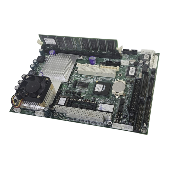
Advantech PCM-9575F User Manual (164 pages)
EBX VIA Eden/Ezra SBC with CPU,LCD, Ethernet, Audio, PCI and PC/104-Plus
Brand:
Advantech
| Category:
Motherboard
| Size: 25 MB
Table of Contents
Packing List
4
Additional Information and Assistance
4
Table of Contents
6
Chapter 1 General Information
12
Chapter 1 Introduction
13
Highly Integrated Multimedia SBC
13
Features
14
Specifications
14
Standard EBX SBC Functions
14
VGA/LCD Interface
15
LVDS: Supports 2 Channel (2 X 18 Bit) LVDS Interface
15
Audio Function
15
TV-Out (Optional)
15
PCI Bus Ethernet Interface
16
Mechanical and Environmental
16
Board Layout: Dimensions
17
Chapter 2 Installation
18
Jumpers
19
Connectors
19
Locating Jumpers
21
Locating Connectors
22
Setting Jumpers
23
Clear CMOS (JP4)
24
Installing Dimms
25
IDE, CDROM Hard Drive Connector (CN14, CN16)
25
Connecting the Hard Drive
25
Solid State Disk
26
Compactflash (CN26)
26
Floppy Drive Connector (CN18)
26
1Connecting the Floppy Drive
26
Parallel Port Connector (CN15)
27
Keyboard and PS/2 Mouse Connector (CN25)
27
Power & HDD LED, Reset Switch (CN13, CN22)
27
1Power & HDD LED (CN13)
28
2Reset Switch (CN22)
28
Power Connectors (CN27, CN5, FAN1)
28
1Peripheral Power Connector, -5 V, -12 V (CN27)
28
2Main Power Connector, +5 V, +12 V (CN5)
28
3CPU Fan Power Supply Connector (FAN1)
28
ATX Power Control Connector (CN3, CN23)
28
1ATX Feature (CN3), Soft Power Switch Conn (CN23)
28
IR Connector (CN24)
29
Audio Interfaces (CN4, CN2)
29
1Audio Connector (CN4)
30
2CD Audio Input Connector (CN2)
30
COM Port Connector (CN19)
30
1COM2 RS-232/422/485 Setting (JP6)
30
VGA/LCD/LVDS Interface Connections
31
1CRT Display Connector (CN8)
31
2Flat Panel Display Connector (CN11)
31
3Extension Flat Panel Connector (CN10)
31
4LVDS LCD Panel Connector (CN9)
31
5Panel Type Selection (S1)
31
TV-Out Interface (Optional) (CN1)
32
Ethernet Configuration
33
1100Base-T Connector (CN12)
33
2Network Boot
33
3LAN Controller Power Select (JP2)
33
Watchdog Timer Configuration
33
1Watchdog Timer Action (JP5)
34
USB Connectors (CN20, CN28)
34
Chapter 3 Software Configuration
37
Introduction
37
Connections to Three Standard Lcds
38
Connections (640 X 480 TFT Color LCD)
38
Connections (1024 X 768 TFT Color LCD)
39
Connections (800 X 600 TFT Color LCD)
40
Ethernet Software Configuration
41
Chapter 4 Award Bios Setup
45
System Test and Initialization
45
System Configuration Verification
45
Award BIOS Setup
46
Entering Setup
46
Standard CMOS Features Setup
47
Advanced BIOS Features Setup
48
Advanced Chipset Features Setup
49
Integrated Peripherals
50
Power Management Setup
50
Pnp/Pci Configurations
51
PC Health Status
51
Frequency/Voltage Control
52
10Load Optimized Defaults
53
11Set Password
53
12Save & Exit Setup
54
13Exit Without Saving
55
Chapter 5 PCI SVGA Setup
57
Introduction
57
Chipset
57
Display Memory
57
Display Types
57
Dual/Simultaneous Display
58
Installation of the SVGA Driver
59
Installation for Windows 95
59
Installation for Windows 98/Me
63
Installation for Windows NT
68
Installation for Windows 2000
73
Installation for Windows XP
78
Further Information
84
Chapter 6 Audio Setup
87
Introduction
87
DOS Utilities
87
VIA Sound Blaster Pro Compatible Set up Program
87
VIA Sound Blaster Installation
88
Driver Installation
88
Before You Begin
88
Windows 95/98 Drivers
89
Windows NT Drivers
96
Windows 2000 Drivers
99
Chapter 7 PCI Bus Ethernet Interface
104
Introduction
105
Installation of Ethernet Driver
105
Installation for MS-DOS and Windows 3.1
105
Installation for Windows 98
106
Installation for Windows 2000
109
Installation for Windows NT
114
Further Information
120
Appendix A Programming the Watchdog Timer
123
Supported Input Timing Modes
123
Appendix B Installing PC/104-Plus Modules
126
Appendix B Installing PC/104-Plus Modules
127
Appendix C Pin Assignments
131
CPU Fan Power Connector (FAN 1)
131
Ethernet 10/100Base-T Connector (CN12)
131
Audio Connector (CN4)
132
Audio in Connector (CN2)
132
Main Power Connector (CN5)
133
Keyboard and PS/2 Mouse Connector (CN25)
134
Floppy Disk Drive Connector (CN18)
135
PC/104 Plus Connectors (CN17)
136
IDE Hard Drive Connector (CN14, CN16)
138
Parallel Port Connector (CN15)
139
Power & HDD LED Connector(CN13)
140
Reset Button Connector (CN22)
140
USB Connector (CN20, CN28)
141
LCD Inverter Backlight Connector (CN6)
141
IR Connector (CN24)
142
CRT Display Connector (CN8)
142
TV (Video) out Connector (CN1)
143
Flat Panel Connector (CN11)
144
Extended Flat Panel Display Connector (CN10)
145
LCD Signal Mapping
146
LVDS Connector (CN9)
147
Peripheral Power Connector (CN27)
147
COM Port Connector (CN19)
148
Compactflash Card Connector (CN26)
149
ATX Power Feature Connector (CN3)
150
Appendix D System Assignments
153
System I/O Ports
153
1St MB Memory Map
154
DMA Channel Assignments
154
Interrupt Assignments
155
Appendix E Optional Extras for the PCM-9575
156
PCM-10586-5A00 Cable Kit for PCM-9575
157
Optional LCD Cables 10.4" TFT LCD Panel (CN14)
158
Optional USB Cable (CN20)
158
ATX Power Control Cable (CN3)
158
Optional PC/104+ to PCI Module
158
Optional 24 Bit LCD Cable Adaptor
158
Appendix F Mechanical Drawings
160
Mechanical Drawings
161
Advertisement
Advertisement
Related Products
Advantech PCM-9570/S
Advantech PCM-9575
Advantech PCM-9574
Advantech PCM-9576F
Advantech PCM-9575F-J0A1
Advantech PCM-9575F-Q0A1
Advantech PCM-9575F-M0A1
Advantech PCM-9570
Advantech PCM-9579
Advantech PCM-9590FG-S2A2E
Advantech Categories
Motherboard
Computer Hardware
Desktop
Touch Panel
Network Router
More Advantech Manuals
Login
Sign In
OR
Sign in with Facebook
Sign in with Google
Upload manual
Upload from disk
Upload from URL